US20100242599A1 - Device, system, and method for determining fitting condition of connector - Google Patents
Device, system, and method for determining fitting condition of connector Download PDFInfo
- Publication number
- US20100242599A1 US20100242599A1 US12/601,088 US60108808A US2010242599A1 US 20100242599 A1 US20100242599 A1 US 20100242599A1 US 60108808 A US60108808 A US 60108808A US 2010242599 A1 US2010242599 A1 US 2010242599A1
- Authority
- US
- United States
- Prior art keywords
- connector
- sound
- acceleration
- information
- determination
- Prior art date
- Legal status (The legal status is an assumption and is not a legal conclusion. Google has not performed a legal analysis and makes no representation as to the accuracy of the status listed.)
- Granted
Links
- 238000000034 method Methods 0.000 title claims abstract description 17
- 230000001133 acceleration Effects 0.000 claims abstract description 141
- 238000001514 detection method Methods 0.000 claims abstract description 41
- 210000005224 forefinger Anatomy 0.000 claims description 9
- 210000003813 thumb Anatomy 0.000 claims description 9
- 230000008878 coupling Effects 0.000 abstract description 14
- 238000010168 coupling process Methods 0.000 abstract description 14
- 238000005859 coupling reaction Methods 0.000 abstract description 14
- 230000008859 change Effects 0.000 description 8
- 210000000078 claw Anatomy 0.000 description 6
- 238000010586 diagram Methods 0.000 description 4
- 238000004891 communication Methods 0.000 description 2
- 230000002950 deficient Effects 0.000 description 2
- 210000003811 finger Anatomy 0.000 description 2
- 238000012545 processing Methods 0.000 description 2
- 238000006243 chemical reaction Methods 0.000 description 1
- 238000013016 damping Methods 0.000 description 1
- 230000000694 effects Effects 0.000 description 1
- 238000002474 experimental method Methods 0.000 description 1
- 239000000284 extract Substances 0.000 description 1
- 230000006872 improvement Effects 0.000 description 1
- 238000003780 insertion Methods 0.000 description 1
- 230000037431 insertion Effects 0.000 description 1
- 238000005259 measurement Methods 0.000 description 1
- 238000012986 modification Methods 0.000 description 1
- 230000004048 modification Effects 0.000 description 1
- 230000005236 sound signal Effects 0.000 description 1
- 230000007704 transition Effects 0.000 description 1
Images


Classifications
-
- H—ELECTRICITY
- H01—ELECTRIC ELEMENTS
- H01R—ELECTRICALLY-CONDUCTIVE CONNECTIONS; STRUCTURAL ASSOCIATIONS OF A PLURALITY OF MUTUALLY-INSULATED ELECTRICAL CONNECTING ELEMENTS; COUPLING DEVICES; CURRENT COLLECTORS
- H01R43/00—Apparatus or processes specially adapted for manufacturing, assembling, maintaining, or repairing of line connectors or current collectors or for joining electric conductors
- H01R43/26—Apparatus or processes specially adapted for manufacturing, assembling, maintaining, or repairing of line connectors or current collectors or for joining electric conductors for engaging or disengaging the two parts of a coupling device
-
- H—ELECTRICITY
- H01—ELECTRIC ELEMENTS
- H01R—ELECTRICALLY-CONDUCTIVE CONNECTIONS; STRUCTURAL ASSOCIATIONS OF A PLURALITY OF MUTUALLY-INSULATED ELECTRICAL CONNECTING ELEMENTS; COUPLING DEVICES; CURRENT COLLECTORS
- H01R13/00—Details of coupling devices of the kinds covered by groups H01R12/70 or H01R24/00 - H01R33/00
- H01R13/64—Means for preventing incorrect coupling
- H01R13/641—Means for preventing incorrect coupling by indicating incorrect coupling; by indicating correct or full engagement
-
- H—ELECTRICITY
- H01—ELECTRIC ELEMENTS
- H01R—ELECTRICALLY-CONDUCTIVE CONNECTIONS; STRUCTURAL ASSOCIATIONS OF A PLURALITY OF MUTUALLY-INSULATED ELECTRICAL CONNECTING ELEMENTS; COUPLING DEVICES; CURRENT COLLECTORS
- H01R2201/00—Connectors or connections adapted for particular applications
- H01R2201/20—Connectors or connections adapted for particular applications for testing or measuring purposes
Definitions
- the present invention relates to a device, a system, and a method for determining a fitting condition of a connector, which are used for electrical components or the like such as an ECU (Engine Control Unit) and a wire harness mounted in a vehicle.
- ECU Engine Control Unit
- wire harness mounted in a vehicle.
- a fitting condition of a connector for connecting wires of an electric system of a vehicle is detected by checking the presence or absence of a sound or checking with eyes during a connector fitting operation, or checking a fitting condition by manual operation, for example, for each connector.
- the connector fitting operation is carried out in a relatively unfavorable acoustical environment and in a narrow space of a vehicle, so it is difficult to reliably perform the checking for every connector. For this reason, it is difficult to secure a sufficient reliability for checking the fitting. Additionally, a certain time is required for the checking, which hinders an improvement in work efficiency.
- Patent Document 1 discloses a method for checking a fitting condition of a connector for the purpose of easily checking the fitting condition of the connector also in an assembly line.
- a vibration detecting section which is attached to an operator detects a vibration produced by a connector at the time of fitting the connector, converts the vibration detected by the vibration detecting section into vibration waveform data, and transmits it.
- the vibration waveform data is received, and data unnecessary for determining the fitting condition is removed from the vibration waveform data, thereby generating data for determination.
- the data for determination thus generated is compared with reference data stored in advance, thereby determining whether the fitting condition of the connector is defective or not.
- Patent Document 1 Japanese Unexamined Patent Application Publication No. 2006-221971
- the method of extracting a sound, analyzing acoustic feature values, and determining the fitting condition of the connector has a problem in that the coupling condition of the connector cannot be checked with accuracy in a workplace in which many similar sounds are produced.
- the present invention has been made to solve the above-mentioned problems, and therefore an object of the present invention is to provide a device, a system, and a method for determining a fitting condition of a connector, which are capable of improving the accuracy for determining a coupling condition of a connector.
- a device for determining a fitting condition of a connector includes: input means that is attached to an operator and receives detection results including sound information and acceleration information which are measured at a time of fitting a connector; sound determination means that determines whether the sound information satisfies predetermined conditions, based on the detection results input to the input means; and acceleration determination means that determines whether the acceleration information satisfies predetermined conditions, based on the detection results input to the input means, in which only when both the sound information and the acceleration information satisfy the predetermined conditions, it is determined that the connector is fitted.
- the present invention in determining the fitting condition, it is determined that the connector is fitted, only when the predetermined sound conditions are satisfied and the predetermined acceleration conditions are also satisfied, which makes it possible to determine whether the connector is appropriately fitted or not, with extremely high accuracy.
- the sound determination means can perform a determination based on at least one of an amount of attenuation of a sound extracted from an amplitude waveform of the sound, the number of peaks indicating an amplitude, and a peak duration for maintaining a peak of a predetermined value or greater.
- the acceleration determination means can perform a determination based on at least one of a slope of a waveform extracted from an acceleration waveform, a peak timing, and a peak interval. As long as the predetermined sound conditions and acceleration conditions can be determined, various determination conditions can be used.
- a trigger timing for the sound information to satisfy the predetermined conditions can be measured, and the acceleration waveform can be determined based on the trigger timing.
- the slopes or the like of the acceleration waveform can be compared based on the trigger timing.
- the acceleration determination means can perform an acceleration determination on detection results satisfying the conditions in the sound determination means, thereby preventing a useless acceleration determination from being made.
- a system for determining a fitting condition of a connector includes: a detector that is attached to an operator and detects sound information and acceleration information at a time of fitting a connector; and a determination device that receives detection results from the detector and determines the fitting condition of the connector, in which the determination device includes: input means that receives the detection results; sound determination means that determines whether the sound information satisfies predetermined conditions, based on the detection results input to the input means; and acceleration determination means that determines whether the acceleration information satisfies predetermined conditions, based on the detection results input to the input means, and only when it is determined that both the sound information and the acceleration information satisfy the predetermined conditions, it is determined that the connector is fitted.
- the determination device determines that the connector is fitted, only when the predetermined sound conditions are satisfied and the predetermined acceleration conditions are also satisfied, which makes it possible to determine whether the connector is appropriately fitted or not, with extremely high accuracy.
- the system further includes a receiver that is connected to the determination device by wireless, and the receiver can set conditions for the sound information and the acceleration information to the determination device.
- the determination is performed by the determination device capable of receiving the detection results via a wire, thereby enabling determination with high accuracy, and the determination results can be displayed, for example, on the receiver.
- the detector can be attached to a thumb and/or a forefinger of the operator.
- a method for determining a fitting condition of a connector includes: a detection step of detecting, by detection means attached to an operator, sound information and acceleration information at a time of fitting a connector; a sound information determination step of determining whether the sound information included in the detection results satisfies predetermined conditions; an acceleration determination step of determining whether the acceleration information included in the detection results satisfies predetermined conditions; and a connector fitting condition determination step of determining that the connecter is fitted, when both the sound information and the acceleration information satisfy the predetermined conditions.
- the fitting condition in determining the fitting condition, it is determined that the connector is fitted, only when the predetermined sound conditions are satisfied and the predetermined acceleration conditions are also satisfied.
- the acceleration determination step can be carried out only when the predetermined conditions are satisfied in the sound information determination step, thereby preventing a useless determination from being made.
- a predetermined timing extracted from the sound information is set as a trigger timing, and a determination is performed using an acceleration waveform based on the trigger timing.
- a device, a system, and a method for determining a fitting condition of a connector which are capable of improving the accuracy for determining a coupling condition of a connector.
- FIG. 1 is a diagram showing a connector fitting determination system according to an embodiment of the present invention
- FIG. 2 is a graph showing a sound waveform of a connector fitting sound and an amount of change in the amplitude over time
- FIG. 3 is a graph showing an acceleration waveform at the time of fitting a connector
- FIG. 4 is an explanatory diagram showing an acceleration waveform at the time of fitting a connector
- FIG. 5A is a graph showing acceleration in the x-axis direction during fitting of a connector
- FIG. 5B is a graph showing acceleration in the y-axis direction during fitting of a connector
- FIG. 6A is a graph showing acceleration in the z-axis direction during fitting of a connector
- FIG. 6B is a graph showing a sound waveform during fitting of a connector
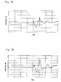
- FIG. 7A is a graph showing acceleration in the x-axis direction when a sound is produced by hitting a fastening tool against a holder in the operation in which a sound similar to the connector fitting sound is produced;
- FIG. 7B is a graph showing acceleration in the y-axis direction when a sound is produced by hitting a fastening tool against a holder in the operation in which a sound similar to the connector fitting sound is produced;
- FIG. 8A is a graph showing acceleration in the z-axis direction when a sound is produced by hitting a fastening tool against a holder in the operation in which a sound similar to the connector fitting sound is produced;
- FIG. 8B is a graph showing a sound waveform obtained when a sound is produced by hitting a fastening tool against a holder in the operation in which a sound similar to the connector fitting sound is produced;
- FIG. 9A is a graph showing acceleration in the x-axis direction when a push-button operation sound is produced in the operation in which a sound similar to the connector fitting sound is produced;
- FIG. 9B is a graph showing acceleration in the y-axis direction when the push-button operation sound is produced in the operation in which a sound similar to the connector fitting sound is produced;
- FIG. 10A is a graph showing acceleration in the z-axis direction when the push-button operation sound is produced in the operation in which a sound similar to the connector fitting sound is produced;
- FIG. 10B is a graph showing a sound waveform when the push-button operation sound is produced in the operation in which a sound similar to the connector fitting sound is produced;
- FIG. 11A is a graph showing acceleration in the x-axis direction when a sound is produced in the case where a bolt is set into a socket in the operation in which a sound similar to the connector fitting sound is produced;
- FIG. 11B is a graph showing acceleration in the y-axis direction when a sound is produced in the case where a bolt is set into a socket in the operation in which a sound similar to the connector fitting sound is produced;
- FIG. 12A is a graph showing acceleration in the z-axis direction when a sound is produced in the case where a bolt is set into a socket in the operation in which a sound similar to the connector fitting sound is produced;
- FIG. 12B is a graph showing a sound waveform when a sound is produced in the case where a bolt is set into a socket in the operation in which a sound similar to the connector fitting sound is produced;
- FIG. 13A is a graph showing acceleration in the x-axis direction when a sound is produced in the case where connectors collide with each other in the operation in which a sound similar to the connector fitting sound is produced;
- FIG. 13B is a graph showing acceleration in the y-axis direction when a sound is produced in the case where connectors collide with each other in the operation in which a sound similar to the connector fitting sound is produced;
- FIG. 14A is a graph showing acceleration in the z-axis direction when a sound is produced in the case where connectors collide with each other in the operation in which a sound similar to the connector fitting sound is produced;
- FIG. 14B is a graph showing a sound waveform when a sound is produced in the case where connectors collide with each other in the operation in which a sound similar to the connector fitting sound is produced.
- FIG. 15 is a flowchart showing a method for determining a fitting condition of a connector according to an embodiment of the present invention.
- FIG. 1 is a diagram showing a connector fitting (connector coupling) determination system according to an embodiment of the present invention.
- a connector fitting determination system 1 is attached to an operator and includes a detector 20 that detects sound information and acceleration information at the time of fitting the connector, a determination device 10 that receives detection results from the detector 20 to determine the fitting condition of the connector, and a receiver 30 that is connected to the determination device 10 by wireless.
- the detector 20 is attached to the thumb and forefinger of the operator, and includes a sensor for the right-hand forefinger 21 , a sensor for the right-hand thumb 22 , a sensor for the left-hand forefinger 23 , and a sensor for the left-hand thumb 24 .
- this embodiment is described with assuming that the measurement is performed with four sensors.
- the sensors may be attached to only the right hand of a right-handed operator or the like who operates with the right hand, or may be attached to only the left hand of an operator who operates with the left hand. More alternatively, the sensor may be attached to only the thumb or forefinger.
- Each sensor includes an integrated microphone/acceleration sensor that detects sounds and acceleration. Note that the microphone and acceleration sensor may be separately mounted.
- the acceleration sensors measure acceleration in six axes in total of the x-axis, y-axis, and z-axis of each of the thumb and forefinger.
- the detection results obtained by the detector 20 are sent to the determination device 10 which is connected to the detector 20 by a wire.
- the determination device 10 includes an input section 11 that receives the detection results, a sound information analysis section 12 that analyzes sound information included in the detection results input to the input section 11 , a sound information determination section 13 that determines whether the sound information satisfies predetermined conditions, based on the analysis results of the sound information analysis section 12 , an acceleration information analysis section 14 that analyzes acceleration information included in the detection results, and an acceleration information determination section 15 that determines whether or not the analysis results of the acceleration information analysis section 14 satisfy predetermined conditions. Additionally, the determination device 10 is connected to a reference value DB 16 that stores a reference value for determining the sound information and a reference value for determining the acceleration information. The determination device 10 determines that the connector is fitted, only when both the sound information and the acceleration information satisfy the predetermined conditions, and transmits the results to the receiver 30 .
- the receiver 30 is composed of a PC or the like, and performs wireless communication with the determination device 10 .
- the receiver 30 can also be connected to a line control or the like in a factory to display determination results, and can display or store waveform data of the collected sounds and acceleration information, for example. Further, the receiver 30 reconfigures the conditions for the sound information and acceleration information stored in the reference value DB 16 which is connected to the determination device 10 or included in the determination device 10 .
- the detector 20 may determine whether the connector is appropriately fitted or not.
- the detector 20 may transmit the determination results to the receiver 30 by wireless.
- the sound information and acceleration information are determined by the detector 20 or the determination device 10 connected to the detector 20 by a wire, thereby making it possible to make a determination with accuracy.
- the receiver 30 may determine whether the connector is appropriately fitted or not, as a matter of course.
- the determination as to whether the connector is appropriately fitted or not is made based on results obtained by measuring the motion (acceleration) of the operator's hand during the connector operation, and based on sound signals obtained at the time of fitting a connector.
- the determination as to whether the connector is fitted is conventionally made by collecting sounds at the time of fitting a connector or collecting vibrations, and analyzing the feature values. These methods, however, have a difficulty in accurately determining whether the connector is fitted in a workplace where many similar sounds or vibrations are produced.
- the acceleration of an operator's hand is measured during the connector operation, and the analysis results and sound analysis results are determined, thereby improving the determination accuracy.
- FIG. 2 is a graph showing a sound waveform of a connector fitting sound and an amount of change in the amplitude over time.
- the sound information analysis section 12 extracts an amount of change in the amplitude over time, based on a frequency (Hz) represented by the horizontal axis and a sound waveform of a sound pressure (dB) represented by the longitudinal axis. Then, based on this amount of change in the amplitude over time, it is determined whether the sound waveform corresponds to the connector fitting sound. As shown in FIG.
- the attenuation may be obtained from a damping width which is obtained after measuring a time period from a peak of a predetermined threshold h 1 or larger to a peak of a predetermined threshold of h 2 or smaller.
- the number of peaks may be obtained such that a timing at which the amplitude exceeds a predetermined value h 3 is set as a trigger timing t 1 and the number of peaks included in a predetermined period is determined based on the trigger timing.
- the peak duration may be a time period in which a peak of a predetermined threshold h 4 or larger is maintained from the trigger timing t 1 .
- the sound information determination section 13 compares the extracted results with the reference values stored in the reference value DB 16 , and determines whether the sound waveform corresponds to the connector fitting sound. Note that the attenuation can also be obtained with being based on the trigger timing t 1 . That is, the attenuation after the elapse of a predetermined time from the trigger timing t 1 may be obtained.
- the sound information analysis section 12 and the sound information determination section 13 may use the features based on which the connector fitting sound can be determined, or may use information different from these pieces of information.
- the reference value DB 16 stores results obtained by measuring features of a connector coupling sound in advance.
- FIG. 3 is a graph showing an acceleration waveform at the time of fitting a connector.
- the horizontal axis represents time, and the longitudinal axis represents acceleration.
- FIG. 4 is an explanatory diagram showing an acceleration waveform at the time of fitting a connector.
- the connector includes a male connector 40 and a female connector 50 .
- the female connector 50 includes a body portion 51 and a claw portion 52 that is coupled to the body portion 51 and fitted into an opening 41 formed in the male connector 40 .
- the acceleration waveform changes from a state T 1 to a state T 4 based on the fitting condition of the connector.
- the state T 1 (timing t 0 -t 1 ) indicates a state from when the female connector 50 starts to be inserted into the male connector 40 until the claw portion 52 is fitted into the opening 41 of the male connector 40 .
- the acceleration sensor indicates an acceleration 101 .
- the acceleration sensor points to a deceleration direction.
- the acceleration sensor indicates a deceleration 102 .
- the above-mentioned sound information analysis section 12 analyzes this amplitude change, and obtains a fitting sound generation timing as the trigger timing t 1 .
- the acceleration information analysis section 14 analyzes the states T 1 to T 4 based on the trigger timing t 1 . In the state T 2 (timing t 1 -t 2 ), the acceleration sensor indicates a rapid acceleration 103 immediately after the fitting.
- the state T 3 indicates a state immediately after the body portion 51 of the female connector 50 is brought into contact with the male connector 40 .
- the acceleration sensor When brought into contact with the side of the male connector 40 , the acceleration sensor indicates a rapid deceleration 104 .
- the state shifts to the state T 4 (timing t 3 -t 4 ).
- the acceleration sensor indicates an acceleration 105 again under a condition of being applied with a reaction force due to inertia immediately after the body portion 51 of the female connector 50 is brought into contact with the male connector 40 .
- the acceleration waveform at the time of fitting a connector shifts from the state T 1 to the state T 4 .
- the fitting sound generation time is set as the trigger timing t 1 and the changes of the acceleration waveform in each state are subjected to arithmetic processing based on the trigger timing t 1 , the determination can be made using the slope, peak time, peak interval, and the like.
- These pieces of feature information are measured in advance and stored in the reference value DB 16 together with the determination conditions for the sound information described above.
- the acceleration information determination section 15 reads out the determination conditions from the reference value DB 16 , and compares the determination conditions with the detection results, thereby determining whether the acceleration waveform corresponds to the acceleration waveform obtained at the time of fitting a connector.
- the acceleration is determined along six axes in total of the x-axis, y-axis, and z-axis of each of the thumb and forefinger. Further, the determination is made also in the state where the plus and minus are reversed. For example, it can be determined that the connector is fitted, when any one of the six axes satisfies the conditions. Note that the number of waveforms among the six axes that satisfy the conditions for determining that the connector is fitted may be arbitrarily set depending on the conditions for determining whether the connector is fitted and circumstances. In this embodiment, the receiver 30 can set and change these conditions as needed.
- FIGS. 5A to 6B are graphs showing the sound information and acceleration information indicating that the connector is fitted.
- FIG. 5A shows acceleration in the x-axis direction
- FIG. 5B acceleration in the y-axis direction
- FIG. 6A acceleration in the z-axis direction
- FIG. 6B a sound waveform.
- the horizontal axis represents time and the longitudinal axis represents acceleration in FIGS. 5A to 6A
- the horizontal axis represents time and the longitudinal axis represents a sound pressure in FIG. 6B .
- FIGS. 7A to 14B which correspond to these figures, show a sound waveform and an acceleration waveform when a sound is produced in the operation which is different from the connector fitting operation and in which a sound similar to the connector fitting sound is produced.
- FIGS. 7A to BB show a sound waveform and an acceleration waveform when a fastening tool is hit against a holder.
- FIGS. 9A to 10B show a sound waveform and an acceleration waveform when a push-button operation sound is produced.
- FIGS. 11A to 12B show a sound waveform and an acceleration waveform when a bolt is set into a socket.
- FIGS. 13A to 14B show a sound waveform and an acceleration waveform when connectors collide with each other.
- the sound waveform obtained at the time of fitting a connector is similar to the waveform of other sounds, which makes it difficult to determine that the connector is fitted, based only on the sound waveform.
- the acceleration waveforms shown in FIGS. 5A to 14C other than the above-mentioned figures a transition from the state T 1 to the state T 4 is not observed.
- the connector fitting can be checked with accuracy. Note that the features of the acceleration waveform at the time of fitting a connector as shown in FIG. 3 appear in any one of the x-axis, y-axis, and z-axis. Accordingly, if these three pieces of information are determined, the connector fitting can be determined.
- FIG. 15 is a flowchart showing a method for determining a fitting condition of a connector according to this embodiment.
- the sound information analysis section 12 first generates the trigger timing (Step S 1 ).
- the trigger timing may be a timing which exceeds a predetermined threshold that is set to a sound waveform.
- the sound waveform is analyzed based on the trigger timing, and the reference values of the reference value DB 16 are compared with various analysis results, thereby determining the sound information (Step S 2 ).
- the attenuation of the amplitude after the elapse of the predetermined time from the trigger timing, the number of peaks of the amplitude included in the predetermined period from the trigger timing, the peak duration for maintaining the amplitude of the predetermined value or larger from the trigger timing, and the like can be used for the determination.
- the acceleration determination is carried out (Step S 3 ).
- the acceleration information analysis section 14 performs arithmetic processing on the changes in waveform from the state T 1 to the state T 4 for 20 ⁇ s before and after the trigger timing, for example, and obtains the slope, peak time, peak interval, and the like, and the acceleration information determination section 15 performs the comparison and determination using the reference values, thereby determining whether the connector is fitted or not.
- sounds and acceleration are measured using a microphone and an accelerometer which are attached to a finger portion of an operator.
- the motion of the finger is captured during the connector operation, and the connector fitting condition is determined together with the results of analyzing the sound information.
- the determination accuracy can be improved.
- acceleration waveforms are different from each other even in the operation in which a sound similar to that of a connector is produced, and therefore the connector fitting can be checked with accuracy.
- the present invention is applicable to a device, a system, and a method for determining a fitting condition of a connector, which are used for electrical components or the like such as an ECU (Engine Control Unit) and a wire harness mounted in a vehicle.
- ECU Engine Control Unit
- wire harness mounted in a vehicle.
Abstract
Provided are a device, a system, and a method for determining a fitting condition of a connector, which are capable of improving the accuracy for determining the coupling condition of the connector. A connector fitting condition determination device (10) includes an input section (11) that is attached to an operator and receives detection results including sound information and acceleration information that are measured at a time of fitting a connector; a sound information determination section (13) that determines whether the sound information satisfies predetermined conditions based on the detection results input to the input section (11); and an acceleration information determination section (15) that determines whether the acceleration information satisfies predetermined conditions, on detection results satisfying the conditions in the sound information determination section 13. The determination device (10) determines that the connector is fitted, only when both the sound information and the acceleration information satisfy the predetermined conditions.
Description
- The present invention relates to a device, a system, and a method for determining a fitting condition of a connector, which are used for electrical components or the like such as an ECU (Engine Control Unit) and a wire harness mounted in a vehicle.
- With recent advances in computerization of in-vehicle devices, the number of connectors for use in a vehicle is rapidly increasing. A fitting condition of a connector for connecting wires of an electric system of a vehicle is detected by checking the presence or absence of a sound or checking with eyes during a connector fitting operation, or checking a fitting condition by manual operation, for example, for each connector.
- However, the connector fitting operation is carried out in a relatively unfavorable acoustical environment and in a narrow space of a vehicle, so it is difficult to reliably perform the checking for every connector. For this reason, it is difficult to secure a sufficient reliability for checking the fitting. Additionally, a certain time is required for the checking, which hinders an improvement in work efficiency.
- In this regard,
Patent Document 1 discloses a method for checking a fitting condition of a connector for the purpose of easily checking the fitting condition of the connector also in an assembly line. In this method, a vibration detecting section which is attached to an operator detects a vibration produced by a connector at the time of fitting the connector, converts the vibration detected by the vibration detecting section into vibration waveform data, and transmits it. The vibration waveform data is received, and data unnecessary for determining the fitting condition is removed from the vibration waveform data, thereby generating data for determination. The data for determination thus generated is compared with reference data stored in advance, thereby determining whether the fitting condition of the connector is defective or not. - [Patent Document 1] Japanese Unexamined Patent Application Publication No. 2006-221971
- However, when the determination as to whether the fitting condition of the connector is defective or not is made based on an amount of vibration at the time of coupling, a vibration signal produced during operation other than the connector fitting operation is detected, and a sufficiently high accuracy cannot be obtained. In other words, the method of extracting a sound, analyzing acoustic feature values, and determining the fitting condition of the connector has a problem in that the coupling condition of the connector cannot be checked with accuracy in a workplace in which many similar sounds are produced.
- In the workplace, there are many fitting operations other than the connector fitting operation, such as clip fitting. If the determination is made based only on sounds, it is impossible to capture a moment of the connector fitting, and thus an erroneous determination is more likely to be made. Accordingly, when the coupling condition is determined based only on the vibration obtained at the time of fitting a connector, the accuracy thereof becomes extremely low, since there are many similar operations. Moreover, the method disclosed in
Patent Document 1 in which a comparison with reference data is made by taking into account a vehicle type, a connector type, and a coupling order, has another problem in that, when operation contents are frequently changed due to an addition of a new vehicle type, an addition of a new connector, or a tact change, the method cannot flexibly deal with these operation contents. - The present invention has been made to solve the above-mentioned problems, and therefore an object of the present invention is to provide a device, a system, and a method for determining a fitting condition of a connector, which are capable of improving the accuracy for determining a coupling condition of a connector.
- A device for determining a fitting condition of a connector according to the present invention includes: input means that is attached to an operator and receives detection results including sound information and acceleration information which are measured at a time of fitting a connector; sound determination means that determines whether the sound information satisfies predetermined conditions, based on the detection results input to the input means; and acceleration determination means that determines whether the acceleration information satisfies predetermined conditions, based on the detection results input to the input means, in which only when both the sound information and the acceleration information satisfy the predetermined conditions, it is determined that the connector is fitted.
- According to the present invention, in determining the fitting condition, it is determined that the connector is fitted, only when the predetermined sound conditions are satisfied and the predetermined acceleration conditions are also satisfied, which makes it possible to determine whether the connector is appropriately fitted or not, with extremely high accuracy.
- Further, the sound determination means can perform a determination based on at least one of an amount of attenuation of a sound extracted from an amplitude waveform of the sound, the number of peaks indicating an amplitude, and a peak duration for maintaining a peak of a predetermined value or greater. The acceleration determination means can perform a determination based on at least one of a slope of a waveform extracted from an acceleration waveform, a peak timing, and a peak interval. As long as the predetermined sound conditions and acceleration conditions can be determined, various determination conditions can be used.
- Furthermore, a trigger timing for the sound information to satisfy the predetermined conditions can be measured, and the acceleration waveform can be determined based on the trigger timing. The slopes or the like of the acceleration waveform can be compared based on the trigger timing.
- Moreover, the acceleration determination means can perform an acceleration determination on detection results satisfying the conditions in the sound determination means, thereby preventing a useless acceleration determination from being made.
- A system for determining a fitting condition of a connector according to the present invention includes: a detector that is attached to an operator and detects sound information and acceleration information at a time of fitting a connector; and a determination device that receives detection results from the detector and determines the fitting condition of the connector, in which the determination device includes: input means that receives the detection results; sound determination means that determines whether the sound information satisfies predetermined conditions, based on the detection results input to the input means; and acceleration determination means that determines whether the acceleration information satisfies predetermined conditions, based on the detection results input to the input means, and only when it is determined that both the sound information and the acceleration information satisfy the predetermined conditions, it is determined that the connector is fitted.
- According to the present invention, based on the detection results from the detector, the determination device determines that the connector is fitted, only when the predetermined sound conditions are satisfied and the predetermined acceleration conditions are also satisfied, which makes it possible to determine whether the connector is appropriately fitted or not, with extremely high accuracy.
- Further, the system further includes a receiver that is connected to the determination device by wireless, and the receiver can set conditions for the sound information and the acceleration information to the determination device. The determination is performed by the determination device capable of receiving the detection results via a wire, thereby enabling determination with high accuracy, and the determination results can be displayed, for example, on the receiver.
- Moreover, the detector can be attached to a thumb and/or a forefinger of the operator.
- A method for determining a fitting condition of a connector according to the present invention includes: a detection step of detecting, by detection means attached to an operator, sound information and acceleration information at a time of fitting a connector; a sound information determination step of determining whether the sound information included in the detection results satisfies predetermined conditions; an acceleration determination step of determining whether the acceleration information included in the detection results satisfies predetermined conditions; and a connector fitting condition determination step of determining that the connecter is fitted, when both the sound information and the acceleration information satisfy the predetermined conditions.
- According to the present invention, in determining the fitting condition, it is determined that the connector is fitted, only when the predetermined sound conditions are satisfied and the predetermined acceleration conditions are also satisfied. Thus, when a coupling sound and changes in acceleration are used for determining the coupling of the connector, highly accurate determination results can be obtained.
- Further, the acceleration determination step can be carried out only when the predetermined conditions are satisfied in the sound information determination step, thereby preventing a useless determination from being made.
- Furthermore, in the acceleration determination step, a predetermined timing extracted from the sound information is set as a trigger timing, and a determination is performed using an acceleration waveform based on the trigger timing. When information about a connector coupling sound is used and changes in acceleration before and after a coupling sound generation time is measured, it is possible to distinguish the connector fitting operation from the other operations, and eliminate the need of taking into account the vehicle type, connector type, coupling order, or the like.
- According to the present invention, it is possible to provide a device, a system, and a method for determining a fitting condition of a connector, which are capable of improving the accuracy for determining a coupling condition of a connector.
-
FIG. 1 is a diagram showing a connector fitting determination system according to an embodiment of the present invention; -
FIG. 2 is a graph showing a sound waveform of a connector fitting sound and an amount of change in the amplitude over time; -
FIG. 3 is a graph showing an acceleration waveform at the time of fitting a connector; -
FIG. 4 is an explanatory diagram showing an acceleration waveform at the time of fitting a connector; -
FIG. 5A is a graph showing acceleration in the x-axis direction during fitting of a connector; -
FIG. 5B is a graph showing acceleration in the y-axis direction during fitting of a connector; -
FIG. 6A is a graph showing acceleration in the z-axis direction during fitting of a connector; -
FIG. 6B is a graph showing a sound waveform during fitting of a connector; -
FIG. 7A is a graph showing acceleration in the x-axis direction when a sound is produced by hitting a fastening tool against a holder in the operation in which a sound similar to the connector fitting sound is produced; -
FIG. 7B is a graph showing acceleration in the y-axis direction when a sound is produced by hitting a fastening tool against a holder in the operation in which a sound similar to the connector fitting sound is produced; -
FIG. 8A is a graph showing acceleration in the z-axis direction when a sound is produced by hitting a fastening tool against a holder in the operation in which a sound similar to the connector fitting sound is produced; -
FIG. 8B is a graph showing a sound waveform obtained when a sound is produced by hitting a fastening tool against a holder in the operation in which a sound similar to the connector fitting sound is produced; -
FIG. 9A is a graph showing acceleration in the x-axis direction when a push-button operation sound is produced in the operation in which a sound similar to the connector fitting sound is produced; -
FIG. 9B is a graph showing acceleration in the y-axis direction when the push-button operation sound is produced in the operation in which a sound similar to the connector fitting sound is produced; -
FIG. 10A is a graph showing acceleration in the z-axis direction when the push-button operation sound is produced in the operation in which a sound similar to the connector fitting sound is produced; -
FIG. 10B is a graph showing a sound waveform when the push-button operation sound is produced in the operation in which a sound similar to the connector fitting sound is produced; -
FIG. 11A is a graph showing acceleration in the x-axis direction when a sound is produced in the case where a bolt is set into a socket in the operation in which a sound similar to the connector fitting sound is produced; -
FIG. 11B is a graph showing acceleration in the y-axis direction when a sound is produced in the case where a bolt is set into a socket in the operation in which a sound similar to the connector fitting sound is produced; -
FIG. 12A is a graph showing acceleration in the z-axis direction when a sound is produced in the case where a bolt is set into a socket in the operation in which a sound similar to the connector fitting sound is produced; -
FIG. 12B is a graph showing a sound waveform when a sound is produced in the case where a bolt is set into a socket in the operation in which a sound similar to the connector fitting sound is produced; -
FIG. 13A is a graph showing acceleration in the x-axis direction when a sound is produced in the case where connectors collide with each other in the operation in which a sound similar to the connector fitting sound is produced; -
FIG. 13B is a graph showing acceleration in the y-axis direction when a sound is produced in the case where connectors collide with each other in the operation in which a sound similar to the connector fitting sound is produced; -
FIG. 14A is a graph showing acceleration in the z-axis direction when a sound is produced in the case where connectors collide with each other in the operation in which a sound similar to the connector fitting sound is produced; -
FIG. 14B is a graph showing a sound waveform when a sound is produced in the case where connectors collide with each other in the operation in which a sound similar to the connector fitting sound is produced; and -
FIG. 15 is a flowchart showing a method for determining a fitting condition of a connector according to an embodiment of the present invention. -
- 10 determination device
- 11 input section
- 12 sound information analysis section
- 13 sound information determination section
- 14 acceleration information analysis section
- 15 acceleration information determination section
- 20 detector
- 21, 23 sensor for forefinger
- 22, 24 sensor for thumb
- 30 receiver
- 40 male connector
- 41 opening
- 50 female connector
- 51 body portion
- 52 claw portion
- Specific embodiments to which the present invention is applied will be described in detail below with reference to the drawings.
FIG. 1 is a diagram showing a connector fitting (connector coupling) determination system according to an embodiment of the present invention. A connectorfitting determination system 1 is attached to an operator and includes adetector 20 that detects sound information and acceleration information at the time of fitting the connector, adetermination device 10 that receives detection results from thedetector 20 to determine the fitting condition of the connector, and areceiver 30 that is connected to thedetermination device 10 by wireless. - The
detector 20 is attached to the thumb and forefinger of the operator, and includes a sensor for the right-hand forefinger 21, a sensor for the right-hand thumb 22, a sensor for the left-hand forefinger 23, and a sensor for the left-hand thumb 24. Note that this embodiment is described with assuming that the measurement is performed with four sensors. Alternatively, the sensors may be attached to only the right hand of a right-handed operator or the like who operates with the right hand, or may be attached to only the left hand of an operator who operates with the left hand. More alternatively, the sensor may be attached to only the thumb or forefinger. Each sensor includes an integrated microphone/acceleration sensor that detects sounds and acceleration. Note that the microphone and acceleration sensor may be separately mounted. The acceleration sensors measure acceleration in six axes in total of the x-axis, y-axis, and z-axis of each of the thumb and forefinger. The detection results obtained by thedetector 20 are sent to thedetermination device 10 which is connected to thedetector 20 by a wire. - The
determination device 10 includes aninput section 11 that receives the detection results, a soundinformation analysis section 12 that analyzes sound information included in the detection results input to theinput section 11, a soundinformation determination section 13 that determines whether the sound information satisfies predetermined conditions, based on the analysis results of the soundinformation analysis section 12, an accelerationinformation analysis section 14 that analyzes acceleration information included in the detection results, and an accelerationinformation determination section 15 that determines whether or not the analysis results of the accelerationinformation analysis section 14 satisfy predetermined conditions. Additionally, thedetermination device 10 is connected to areference value DB 16 that stores a reference value for determining the sound information and a reference value for determining the acceleration information. Thedetermination device 10 determines that the connector is fitted, only when both the sound information and the acceleration information satisfy the predetermined conditions, and transmits the results to thereceiver 30. - The
receiver 30 is composed of a PC or the like, and performs wireless communication with thedetermination device 10. Thereceiver 30 can also be connected to a line control or the like in a factory to display determination results, and can display or store waveform data of the collected sounds and acceleration information, for example. Further, thereceiver 30 reconfigures the conditions for the sound information and acceleration information stored in thereference value DB 16 which is connected to thedetermination device 10 or included in thedetermination device 10. - Note that this embodiment is described with assuming that the
determination device 10 connected to thedetector 20 by a wire determines whether the connector is appropriately fitted or not. Alternatively, thedetector 20 may determine whether the connector is appropriately fitted or not. In this case, thedetector 20 may transmit the determination results to thereceiver 30 by wireless. Thus, instead of determining whether the connector is appropriately fitted or not by transmitting the detected sound information and acceleration information to thereceiver 30 capable of wireless data communication, the sound information and acceleration information are determined by thedetector 20 or thedetermination device 10 connected to thedetector 20 by a wire, thereby making it possible to make a determination with accuracy. Meanwhile, when satisfactory data can be transmitted by wireless, or when the determination as to whether the connector is appropriately fitted or not can be made using data received by wireless depending on determination conditions or the like, thereceiver 30 may determine whether the connector is appropriately fitted or not, as a matter of course. - In this embodiment, the determination as to whether the connector is appropriately fitted or not is made based on results obtained by measuring the motion (acceleration) of the operator's hand during the connector operation, and based on sound signals obtained at the time of fitting a connector. As described above, the determination as to whether the connector is fitted is conventionally made by collecting sounds at the time of fitting a connector or collecting vibrations, and analyzing the feature values. These methods, however, have a difficulty in accurately determining whether the connector is fitted in a workplace where many similar sounds or vibrations are produced. Thus, in this embodiment, the acceleration of an operator's hand is measured during the connector operation, and the analysis results and sound analysis results are determined, thereby improving the determination accuracy.
- First, the sound
information analysis section 12 and the soundinformation determination section 13 will be described.FIG. 2 is a graph showing a sound waveform of a connector fitting sound and an amount of change in the amplitude over time. As shown inFIG. 2 , the soundinformation analysis section 12 extracts an amount of change in the amplitude over time, based on a frequency (Hz) represented by the horizontal axis and a sound waveform of a sound pressure (dB) represented by the longitudinal axis. Then, based on this amount of change in the amplitude over time, it is determined whether the sound waveform corresponds to the connector fitting sound. As shown inFIG. 2 , attenuation in amplitude, the number of peaks of an amplitude, a peak duration, and the like are extracted as the amount of change in the amplitude over time. For example, the attenuation may be obtained from a damping width which is obtained after measuring a time period from a peak of a predetermined threshold h1 or larger to a peak of a predetermined threshold of h2 or smaller. Further, the number of peaks may be obtained such that a timing at which the amplitude exceeds a predetermined value h3 is set as a trigger timing t1 and the number of peaks included in a predetermined period is determined based on the trigger timing. The peak duration may be a time period in which a peak of a predetermined threshold h4 or larger is maintained from the trigger timing t1. - The sound
information determination section 13 compares the extracted results with the reference values stored in thereference value DB 16, and determines whether the sound waveform corresponds to the connector fitting sound. Note that the attenuation can also be obtained with being based on the trigger timing t1. That is, the attenuation after the elapse of a predetermined time from the trigger timing t1 may be obtained. Herein, the soundinformation analysis section 12 and the soundinformation determination section 13 may use the features based on which the connector fitting sound can be determined, or may use information different from these pieces of information. Thereference value DB 16 stores results obtained by measuring features of a connector coupling sound in advance. - Next, the acceleration
information analysis section 14 and the accelerationinformation determination section 15 will be described.FIG. 3 is a graph showing an acceleration waveform at the time of fitting a connector. The horizontal axis represents time, and the longitudinal axis represents acceleration.FIG. 4 is an explanatory diagram showing an acceleration waveform at the time of fitting a connector. Herein, a description is given of an acceleration waveform at the time of fitting a connector having a shape shown inFIG. 4 . The connector includes amale connector 40 and afemale connector 50. Thefemale connector 50 includes abody portion 51 and aclaw portion 52 that is coupled to thebody portion 51 and fitted into anopening 41 formed in themale connector 40. - As shown in
FIGS. 3 and 4 , the acceleration waveform changes from a state T1 to a state T4 based on the fitting condition of the connector. The state T1 (timing t0-t1) indicates a state from when thefemale connector 50 starts to be inserted into themale connector 40 until theclaw portion 52 is fitted into theopening 41 of themale connector 40. First, at the time when insertion of thefemale connector 50 is started, the acceleration sensor indicates anacceleration 101. Next, when theclaw portion 52 of thefemale connector 50 starts to be brought into contact with themale connector 40 and deformed, the acceleration sensor points to a deceleration direction. Then, when theclaw portion 52 of thefemale connector 50 is inserted while being deformed, the acceleration sensor indicates adeceleration 102. - Then, the
claw portion 52 of thefemale connector 50 is completely fitted into the opening of themale connector 40. At this point, the connector produces a fitting sound, and the amplitude of the sound waveform becomes maximum. The above-mentioned soundinformation analysis section 12 analyzes this amplitude change, and obtains a fitting sound generation timing as the trigger timing t1. The accelerationinformation analysis section 14 analyzes the states T1 to T4 based on the trigger timing t1. In the state T2 (timing t1-t2), the acceleration sensor indicates arapid acceleration 103 immediately after the fitting. - Then, the state shifts to the state T3 (timing t2-t3). The state T3 indicates a state immediately after the
body portion 51 of thefemale connector 50 is brought into contact with themale connector 40. When brought into contact with the side of themale connector 40, the acceleration sensor indicates arapid deceleration 104. - Then, the state shifts to the state T4 (timing t3-t4). In the state T4, the acceleration sensor indicates an
acceleration 105 again under a condition of being applied with a reaction force due to inertia immediately after thebody portion 51 of thefemale connector 50 is brought into contact with themale connector 40. - In this manner, the acceleration waveform at the time of fitting a connector shifts from the state T1 to the state T4. When the fitting sound generation time is set as the trigger timing t1 and the changes of the acceleration waveform in each state are subjected to arithmetic processing based on the trigger timing t1, the determination can be made using the slope, peak time, peak interval, and the like. These pieces of feature information are measured in advance and stored in the
reference value DB 16 together with the determination conditions for the sound information described above. The accelerationinformation determination section 15 reads out the determination conditions from thereference value DB 16, and compares the determination conditions with the detection results, thereby determining whether the acceleration waveform corresponds to the acceleration waveform obtained at the time of fitting a connector. - In this embodiment, the acceleration is determined along six axes in total of the x-axis, y-axis, and z-axis of each of the thumb and forefinger. Further, the determination is made also in the state where the plus and minus are reversed. For example, it can be determined that the connector is fitted, when any one of the six axes satisfies the conditions. Note that the number of waveforms among the six axes that satisfy the conditions for determining that the connector is fitted may be arbitrarily set depending on the conditions for determining whether the connector is fitted and circumstances. In this embodiment, the
receiver 30 can set and change these conditions as needed. -
FIGS. 5A to 6B are graphs showing the sound information and acceleration information indicating that the connector is fitted.FIG. 5A shows acceleration in the x-axis direction;FIG. 5B , acceleration in the y-axis direction;FIG. 6A , acceleration in the z-axis direction; andFIG. 6B , a sound waveform. The horizontal axis represents time and the longitudinal axis represents acceleration inFIGS. 5A to 6A , and the horizontal axis represents time and the longitudinal axis represents a sound pressure inFIG. 6B . -
FIGS. 7A to 14B , which correspond to these figures, show a sound waveform and an acceleration waveform when a sound is produced in the operation which is different from the connector fitting operation and in which a sound similar to the connector fitting sound is produced.FIGS. 7A to BB show a sound waveform and an acceleration waveform when a fastening tool is hit against a holder.FIGS. 9A to 10B show a sound waveform and an acceleration waveform when a push-button operation sound is produced.FIGS. 11A to 12B show a sound waveform and an acceleration waveform when a bolt is set into a socket.FIGS. 13A to 14B show a sound waveform and an acceleration waveform when connectors collide with each other. - As shown in
FIGS. 6B , 8B, 10B, 12B, and 14B, the sound waveform obtained at the time of fitting a connector is similar to the waveform of other sounds, which makes it difficult to determine that the connector is fitted, based only on the sound waveform. Meanwhile, in the acceleration waveforms shown inFIGS. 5A to 14C other than the above-mentioned figures, a transition from the state T1 to the state T4 is not observed. Thus, through the analysis of the acceleration waveform as well as the sound waveform, the connector fitting can be checked with accuracy. Note that the features of the acceleration waveform at the time of fitting a connector as shown inFIG. 3 appear in any one of the x-axis, y-axis, and z-axis. Accordingly, if these three pieces of information are determined, the connector fitting can be determined. -
FIG. 15 is a flowchart showing a method for determining a fitting condition of a connector according to this embodiment. As shown inFIG. 15 , the soundinformation analysis section 12 first generates the trigger timing (Step S1). The trigger timing may be a timing which exceeds a predetermined threshold that is set to a sound waveform. - Then, the sound waveform is analyzed based on the trigger timing, and the reference values of the
reference value DB 16 are compared with various analysis results, thereby determining the sound information (Step S2). In this case, as described above, the attenuation of the amplitude after the elapse of the predetermined time from the trigger timing, the number of peaks of the amplitude included in the predetermined period from the trigger timing, the peak duration for maintaining the amplitude of the predetermined value or larger from the trigger timing, and the like can be used for the determination. - Then, when the conditions are satisfied in the sound
information determination section 13, the acceleration determination is carried out (Step S3). Note that when the predetermined conditions are not satisfied in the sound determination, it is determined that the sound does not correspond to the connector fitting sound (Step S5). In the acceleration determination, as described above, the accelerationinformation analysis section 14 performs arithmetic processing on the changes in waveform from the state T1 to the state T4 for 20 μs before and after the trigger timing, for example, and obtains the slope, peak time, peak interval, and the like, and the accelerationinformation determination section 15 performs the comparison and determination using the reference values, thereby determining whether the connector is fitted or not. - In this embodiment, sounds and acceleration are measured using a microphone and an accelerometer which are attached to a finger portion of an operator. The motion of the finger is captured during the connector operation, and the connector fitting condition is determined together with the results of analyzing the sound information. Thus, the determination accuracy can be improved. According to the experiments conducted by the present inventors, acceleration waveforms are different from each other even in the operation in which a sound similar to that of a connector is produced, and therefore the connector fitting can be checked with accuracy.
- Note that the present invention is not limited to the above-mentioned embodiments, and various modification can be made without departing from the gist of the present invention as a matter of course.
- The present invention is applicable to a device, a system, and a method for determining a fitting condition of a connector, which are used for electrical components or the like such as an ECU (Engine Control Unit) and a wire harness mounted in a vehicle.
Claims (11)
1. (canceled)
2. A device for determining a fitting condition of a connector, comprising:
input unit that is attached to an operator and receives detection results including sound information and acceleration information, the sound information and acceleration information being measured at a time of fitting a connector;
sound determination unit that determines whether at least one of an amount of attenuation of a sound extracted from an amplitude waveform of the sound, the number of peaks indicating an amplitude, and a peak duration for maintaining a peak of a predetermined value or greater of the sound information satisfies predetermined conditions, based on the detection results input to the input unit; and
acceleration determination unit that determines whether the acceleration information satisfies predetermined conditions, based on the detection results input to the input unit,
wherein when it is determined that the predetermined conditions are satisfied in both the sound determination unit and the acceleration determination unit, it is determined that the connector is fitted.
3. A device for determining a fitting condition of a connector, comprising:
input unit that is attached to an operator and receives detection results including sound information and acceleration information, the sound information and acceleration information being measured at a time of fitting a connector;
sound determination unit that determines whether the sound information satisfies predetermined conditions, based on the detection results input to the input unit; and
acceleration determination unit that determines whether at least one of a slope of a waveform extracted from an acceleration waveform, a peak timing, and a peak interval of the acceleration information satisfies predetermined conditions, based on the detection results input to the input unit,
wherein when it is determined that the predetermined conditions are satisfied in both the sound determination unit and the acceleration determination unit, it is determined that the connector is fitted.
4. The device for determining a fitting condition of a connector according to claim 3 , wherein a trigger timing for the sound information to satisfy the predetermined conditions is measured, and the acceleration waveform is determined based on the trigger timing.
5. The device for determining a fitting condition of a connector according to claim 2 , wherein the acceleration determination unit performs an acceleration determination on detection results satisfying the conditions in the sound determination unit.
6. (canceled)
7. A system for determining a fitting condition of a connector, comprising:
a detector that is attached to an operator and detects sound information and acceleration information at a time of fitting a connector;
a determination device that receives detection results from the detector and determines the fitting condition of the connector; and
a receiver that is connected to the determination device by wireless and sets conditions for the sound information and the acceleration information to the determination device, wherein
the determination device comprises:
input unit that receives the detection results;
sound determination unit that determines whether the sound information satisfies predetermined conditions, based on the detection results input to the input unit; and
acceleration determination unit that determines whether the acceleration information satisfies predetermined conditions, based on the detection results input to the input unit,
when it is determined that the predetermined conditions are satisfied in both the sound determination unit and the acceleration determination unit, it is determined that the connector is fitted, and
the receiver sets the conditions for the sound information and the acceleration information to the determination device.
8. A system for determining a fitting condition of a connector, comprising:
a detector that is attached to a thumb and/or a forefinger of the operator and detects sound information and acceleration information at a time of fitting a connector; and
a determination device that receives detection results from the detector and determines the fitting condition of the connector, wherein
the determination device comprises:
input unit that receives the detection results;
sound determination unit that determines whether the sound information satisfies predetermined conditions, based on the detection results input to the input unit; and
acceleration determination unit that determines whether the acceleration information satisfies predetermined conditions, based on the detection results input to the input unit, and
when it is determined that the predetermined conditions are satisfied in both the sound determination unit and the acceleration determination unit, it is determined that the connector is fitted.
9. A method for determining a fitting condition of a connector, comprising:
detecting, by detection unit attached to an operator, sound information and acceleration information at a time of fitting a connector;
determining whether the sound information included in the detection results satisfies predetermined conditions;
determining whether the acceleration information included in the detection results satisfies predetermined conditions, assuming that a predetermined timing extracted from the sound information is set as a trigger timing and an acceleration waveform is used based on the trigger timing; and
determining that the connecter is fitted, when it is determined that the predetermined conditions are satisfied in both the sound determination and the acceleration determination.
10. The method for determining a fitting condition of a connector according to claim 9 , wherein the acceleration determination stop is carried out when the predetermined conditions are satisfied in the sound information determination.
11. (canceled)
Applications Claiming Priority (3)
| Application Number | Priority Date | Filing Date | Title |
|---|---|---|---|
| JP2007138095A JP4595962B2 (en) | 2007-05-24 | 2007-05-24 | Connector fitting state determination device and method |
| JP2007-138095 | 2007-05-24 | ||
| PCT/JP2008/059164 WO2008143226A1 (en) | 2007-05-24 | 2008-05-20 | Device, system, and method for determining fitting condition of connector |
Publications (2)
| Publication Number | Publication Date |
|---|---|
| US20100242599A1 true US20100242599A1 (en) | 2010-09-30 |
| US8186216B2 US8186216B2 (en) | 2012-05-29 |
Family
ID=40031923
Family Applications (1)
| Application Number | Title | Priority Date | Filing Date |
|---|---|---|---|
| US12/601,088 Expired - Fee Related US8186216B2 (en) | 2007-05-24 | 2008-05-20 | Device, system, and method for determining fitting condition of connector |
Country Status (6)
| Country | Link |
|---|---|
| US (1) | US8186216B2 (en) |
| EP (1) | EP2161796A4 (en) |
| JP (1) | JP4595962B2 (en) |
| CN (1) | CN101682161B (en) |
| CA (1) | CA2687642C (en) |
| WO (1) | WO2008143226A1 (en) |
Cited By (8)
| Publication number | Priority date | Publication date | Assignee | Title |
|---|---|---|---|---|
| US20130268792A1 (en) * | 2012-04-10 | 2013-10-10 | Lapis Semiconductor Co., Ltd. | Semiconductor device and electrical terminal |
| US20150098574A1 (en) * | 2013-10-07 | 2015-04-09 | Tyco Electronics Corporation | Connector mating assurance system and method |
| US20160249147A1 (en) * | 2015-02-23 | 2016-08-25 | Tyco Electronics Corporation | Mating assurance system and method |
| US9939483B2 (en) | 2015-10-07 | 2018-04-10 | Te Connectivity Corporation | Connector mating assurance system and method |
| US10184970B2 (en) | 2015-10-07 | 2019-01-22 | Te Connectivity Corporation | Connector mating assurance system and method |
| DE102018128622A1 (en) * | 2018-11-15 | 2020-05-20 | Bayerische Motoren Werke Aktiengesellschaft | Method and device for checking plug connections |
| US20210003535A1 (en) * | 2019-07-04 | 2021-01-07 | Fanuc Corporation | Inspection device for determining insertion of connector, and robot device having inspection device |
| US20220207978A1 (en) * | 2019-06-21 | 2022-06-30 | Hitachi, Ltd. | Work content detection determination device, work content detection determination system, and wearable sensor embedded glove |
Families Citing this family (12)
| Publication number | Priority date | Publication date | Assignee | Title |
|---|---|---|---|---|
| JP5040684B2 (en) * | 2008-01-30 | 2012-10-03 | 日産自動車株式会社 | Connector fitting state confirmation device and method |
| JP5034058B2 (en) * | 2009-01-09 | 2012-09-26 | トヨタ自動車東日本株式会社 | Connector fitting inspection system and method |
| JP5215331B2 (en) * | 2010-02-03 | 2013-06-19 | トヨタ自動車東日本株式会社 | Work determination system, work determination method, and recording medium recording the work determination method |
| DE102012004165A1 (en) * | 2012-03-05 | 2013-09-05 | Voss Automotive Gmbh | Control system and method for controlling the assembly of a coupling device |
| KR101518849B1 (en) * | 2013-11-21 | 2015-05-13 | 한일이화 주식회사 | Inspection system of connection condition for cable connector and inspection method using the same |
| FR3024522B1 (en) * | 2014-07-30 | 2017-03-17 | Hutchinson | SYSTEM AND METHOD FOR DETECTING THE LATCHING OF A MANUAL CONNECTION OF A QUICK COUPLING CONNECTION. |
| DE102014016153A1 (en) * | 2014-11-04 | 2016-05-04 | A.RAYMOND et Cie. SCS | Device and method for monitoring an assembly of two components to be connected by means of a clip fastening |
| DE102016213536A1 (en) * | 2016-07-25 | 2018-01-25 | Bayerische Motoren Werke Aktiengesellschaft | Method for monitoring the assembly of connectors |
| JP6792520B2 (en) * | 2017-06-12 | 2020-11-25 | 日本電信電話株式会社 | Detection system |
| US10718660B2 (en) | 2017-06-13 | 2020-07-21 | Robert Bosch Gmbh | Closure detection system |
| JP2022108100A (en) * | 2021-01-12 | 2022-07-25 | 本田技研工業株式会社 | Power supply device |
| EP4283801A1 (en) * | 2021-01-20 | 2023-11-29 | Panasonic Intellectual Property Management Co., Ltd. | Fitting detection method, fitting detection device, and fitting detection system |
Family Cites Families (6)
| Publication number | Priority date | Publication date | Assignee | Title |
|---|---|---|---|---|
| JP2953740B2 (en) * | 1990-04-17 | 1999-09-27 | ザ ウィタカー コーポレーション | Connector mating confirmation method and device |
| JPH07185952A (en) * | 1993-12-27 | 1995-07-25 | Nissan Motor Co Ltd | Device for judging result of part assembly |
| US6368155B1 (en) * | 1999-07-16 | 2002-04-09 | Molex Incorporated | Intelligent sensing connectors |
| JP4920191B2 (en) * | 2005-02-10 | 2012-04-18 | 日産自動車株式会社 | Connector fitting state confirmation device and method |
| JP2007004073A (en) * | 2005-06-27 | 2007-01-11 | Toyota Motor Corp | Sound collecting device |
| JP2008226506A (en) | 2007-03-09 | 2008-09-25 | Kanto Auto Works Ltd | Connection state judging device of connector |
-
2007
- 2007-05-24 JP JP2007138095A patent/JP4595962B2/en not_active Expired - Fee Related
-
2008
- 2008-05-20 EP EP08752960.8A patent/EP2161796A4/en not_active Withdrawn
- 2008-05-20 US US12/601,088 patent/US8186216B2/en not_active Expired - Fee Related
- 2008-05-20 WO PCT/JP2008/059164 patent/WO2008143226A1/en active Application Filing
- 2008-05-20 CA CA2687642A patent/CA2687642C/en not_active Expired - Fee Related
- 2008-05-20 CN CN2008800173319A patent/CN101682161B/en not_active Expired - Fee Related
Cited By (13)
| Publication number | Priority date | Publication date | Assignee | Title |
|---|---|---|---|---|
| US20130268792A1 (en) * | 2012-04-10 | 2013-10-10 | Lapis Semiconductor Co., Ltd. | Semiconductor device and electrical terminal |
| US9298248B2 (en) * | 2012-04-10 | 2016-03-29 | Lapis Semiconductor Co., Ltd. | Semiconductor device and electrical terminal |
| US20150098574A1 (en) * | 2013-10-07 | 2015-04-09 | Tyco Electronics Corporation | Connector mating assurance system and method |
| US9491557B2 (en) * | 2013-10-07 | 2016-11-08 | Tyco Electronics Corporation | Connector mating assurance system and method |
| US20160249147A1 (en) * | 2015-02-23 | 2016-08-25 | Tyco Electronics Corporation | Mating assurance system and method |
| US9813832B2 (en) * | 2015-02-23 | 2017-11-07 | Te Connectivity Corporation | Mating assurance system and method |
| US9939483B2 (en) | 2015-10-07 | 2018-04-10 | Te Connectivity Corporation | Connector mating assurance system and method |
| US10184970B2 (en) | 2015-10-07 | 2019-01-22 | Te Connectivity Corporation | Connector mating assurance system and method |
| DE102018128622A1 (en) * | 2018-11-15 | 2020-05-20 | Bayerische Motoren Werke Aktiengesellschaft | Method and device for checking plug connections |
| US20220207978A1 (en) * | 2019-06-21 | 2022-06-30 | Hitachi, Ltd. | Work content detection determination device, work content detection determination system, and wearable sensor embedded glove |
| US11900777B2 (en) * | 2019-06-21 | 2024-02-13 | Hitachi, Ltd. | Work content detection determination device, work content detection determination system, and wearable sensor embedded glove |
| US20210003535A1 (en) * | 2019-07-04 | 2021-01-07 | Fanuc Corporation | Inspection device for determining insertion of connector, and robot device having inspection device |
| US11668679B2 (en) * | 2019-07-04 | 2023-06-06 | Fanuc Corporation | Inspection device for determining insertion of connector, and robot device having inspection device |
Also Published As
| Publication number | Publication date |
|---|---|
| CN101682161B (en) | 2011-07-13 |
| JP2008293794A (en) | 2008-12-04 |
| WO2008143226A1 (en) | 2008-11-27 |
| CA2687642C (en) | 2011-10-11 |
| JP4595962B2 (en) | 2010-12-08 |
| EP2161796A4 (en) | 2013-11-06 |
| CA2687642A1 (en) | 2008-11-27 |
| CN101682161A (en) | 2010-03-24 |
| US8186216B2 (en) | 2012-05-29 |
| EP2161796A1 (en) | 2010-03-10 |
Similar Documents
| Publication | Publication Date | Title |
|---|---|---|
| US8186216B2 (en) | Device, system, and method for determining fitting condition of connector | |
| JP5034058B2 (en) | Connector fitting inspection system and method | |
| EP1657022A1 (en) | Impact detection device | |
| US10184970B2 (en) | Connector mating assurance system and method | |
| JP2006221971A (en) | Apparatus and method for confirming fitting state of connector | |
| CN102548483B (en) | Ultrasonic diagnostic device | |
| EP1253404A3 (en) | Pedestrian navigation method and apparatus operative in a dead reckoning mode | |
| US20180263314A1 (en) | Device And Method For Monitoring An Assembly Of Two Components To Be Connected By Means of A Clip Fastening | |
| CN107258038B (en) | Cooperation guarantees system and method | |
| WO2008058175A3 (en) | Systems and methods for dynamic situational signal processing for target detection and classification | |
| WO2003023528A3 (en) | Monitoring system, method for the process-parallel monitoring of collision or overload situations in machine tools | |
| KR101219826B1 (en) | A pulse control apparatus evaluating air bag control unit for car and method thereof, a evaluating air bag control unit and pulse processing method thereof, a system evaluating air bag control unit for car and method thereof | |
| CN112129399A (en) | Knocking sensor algorithm and knocking sensor thereof | |
| JP2010186651A (en) | Connector insertion-coupling determination device and connector insertion-coupling determination method | |
| JP5284179B2 (en) | Work determination system, work determination method, and recording medium recording the work determination method | |
| EP1293399A3 (en) | Collision detecting apparatus for vehicle | |
| CN105682862A (en) | Handheld or semistationary machine tool or work tool | |
| US20040032322A1 (en) | Device for sensing lateral impact | |
| JP5040684B2 (en) | Connector fitting state confirmation device and method | |
| US11900777B2 (en) | Work content detection determination device, work content detection determination system, and wearable sensor embedded glove | |
| KR102463154B1 (en) | closure detection system | |
| JP2009169556A (en) | Tracing system | |
| JP2022112143A (en) | Fitting work confirmation system | |
| JP2004273195A (en) | Engagement assurance system, working position indication system, engagement assurance method, and working position indication method | |
| JP2023112729A (en) | Fitting work confirmation system |
Legal Events
| Date | Code | Title | Description |
|---|---|---|---|
| AS | Assignment |
Owner name: TOYOTA JIDOSHA KABUSHIKI KAISHA, JAPAN Free format text: ASSIGNMENT OF ASSIGNORS INTEREST;ASSIGNORS:OGAWA, TATSUYA;ISHIHARA, AKIRA;REEL/FRAME:023549/0964 Effective date: 20091026 |
|
| FEPP | Fee payment procedure |
Free format text: PAYOR NUMBER ASSIGNED (ORIGINAL EVENT CODE: ASPN); ENTITY STATUS OF PATENT OWNER: LARGE ENTITY |
|
| REMI | Maintenance fee reminder mailed | ||
| LAPS | Lapse for failure to pay maintenance fees | ||
| STCH | Information on status: patent discontinuation |
Free format text: PATENT EXPIRED DUE TO NONPAYMENT OF MAINTENANCE FEES UNDER 37 CFR 1.362 |
|
| FP | Lapsed due to failure to pay maintenance fee |
Effective date: 20160529 |