US20090217618A1 - Systems and methods for in-line base plate termination in monopole structures - Google Patents
Systems and methods for in-line base plate termination in monopole structures Download PDFInfo
- Publication number
- US20090217618A1 US20090217618A1 US12/040,799 US4079908A US2009217618A1 US 20090217618 A1 US20090217618 A1 US 20090217618A1 US 4079908 A US4079908 A US 4079908A US 2009217618 A1 US2009217618 A1 US 2009217618A1
- Authority
- US
- United States
- Prior art keywords
- base plate
- monopole
- bolt holes
- lower base
- web plates
- Prior art date
- Legal status (The legal status is an assumption and is not a legal conclusion. Google has not performed a legal analysis and makes no representation as to the accuracy of the status listed.)
- Granted
Links
Images


Classifications
-
- E—FIXED CONSTRUCTIONS
- E04—BUILDING
- E04H—BUILDINGS OR LIKE STRUCTURES FOR PARTICULAR PURPOSES; SWIMMING OR SPLASH BATHS OR POOLS; MASTS; FENCING; TENTS OR CANOPIES, IN GENERAL
- E04H12/00—Towers; Masts or poles; Chimney stacks; Water-towers; Methods of erecting such structures
- E04H12/02—Structures made of specified materials
- E04H12/08—Structures made of specified materials of metal
- E04H12/085—Details of flanges for tubular masts
-
- E—FIXED CONSTRUCTIONS
- E04—BUILDING
- E04H—BUILDINGS OR LIKE STRUCTURES FOR PARTICULAR PURPOSES; SWIMMING OR SPLASH BATHS OR POOLS; MASTS; FENCING; TENTS OR CANOPIES, IN GENERAL
- E04H12/00—Towers; Masts or poles; Chimney stacks; Water-towers; Methods of erecting such structures
- E04H12/22—Sockets or holders for poles or posts
- E04H12/2253—Mounting poles or posts to the holder
- E04H12/2261—Mounting poles or posts to the holder on a flat base
-
- F—MECHANICAL ENGINEERING; LIGHTING; HEATING; WEAPONS; BLASTING
- F16—ENGINEERING ELEMENTS AND UNITS; GENERAL MEASURES FOR PRODUCING AND MAINTAINING EFFECTIVE FUNCTIONING OF MACHINES OR INSTALLATIONS; THERMAL INSULATION IN GENERAL
- F16B—DEVICES FOR FASTENING OR SECURING CONSTRUCTIONAL ELEMENTS OR MACHINE PARTS TOGETHER, e.g. NAILS, BOLTS, CIRCLIPS, CLAMPS, CLIPS OR WEDGES; JOINTS OR JOINTING
- F16B2200/00—Constructional details of connections not covered for in other groups of this subclass
- F16B2200/50—Flanged connections
-
- Y—GENERAL TAGGING OF NEW TECHNOLOGICAL DEVELOPMENTS; GENERAL TAGGING OF CROSS-SECTIONAL TECHNOLOGIES SPANNING OVER SEVERAL SECTIONS OF THE IPC; TECHNICAL SUBJECTS COVERED BY FORMER USPC CROSS-REFERENCE ART COLLECTIONS [XRACs] AND DIGESTS
- Y10—TECHNICAL SUBJECTS COVERED BY FORMER USPC
- Y10T—TECHNICAL SUBJECTS COVERED BY FORMER US CLASSIFICATION
- Y10T403/00—Joints and connections
- Y10T403/71—Rod side to plate or side
- Y10T403/7117—Flanged or grooved rod
Definitions
- Embodiments of the present invention relate generally to monopole structures, and more particularly to end termination support and section splices for monopole structures.
- Monopole structures typically house antennae and other communications equipment. Such structures often include a long, hollow pole structure which is connected to an underlying surface such as a concrete pad formed in the ground. Monopole structures are also used for other purposes, such as, for example, light fixtures, flag poles, and utility poles. As such, monopole structures are typically subjected to wind or other types of forces along their length, which bend or sway the monopole structures. These forces create a torque about the base termination, which in turn stresses the base termination location and can lead to fatigue and eventual failure of the base termination material.
- monopole structures are often connected to an underlying concrete pad via a base termination plate with one or more flanges which protrude from the monopole structure.
- Bolts are often placed through the protruding flange of the base termination plate, and secured to the underlying pad. Placement of the bolts at a radial distance from the outside of the monopole structure (e.g. eccentric loading) enhances the torque experienced by the termination plate, increasing the stress distribution on the pole shaft just above the weld line. This secondary moment causing fatigue in the pole shaft can lead to a shorter life span with a higher risk of cracking at the welds and ultimate failure.
- An inline base plate termination system includes an upper base plate configured to be joined to a bottom end of a monopole, a lower base plate substantially parallel to the upper base plate, the lower base plate having a plurality of bolt holes, and a plurality of web plates connecting the upper base plate with the lower base plate, wherein a virtual projection of the monopole through the lower base plate intersects the plurality of bolt holes.
- each of the plurality of web plates is oriented radially with respect to an axial centerline of the monopole, and each of the plurality of bolt holes may be formed in the lower base plate at an equal distance from the axial centerline and evenly spaced circumferentially around the lower base plate.
- each of the plurality of web plates connects to the lower base plate at a midpoint between two adjacent bolt holes of the plurality of bolt holes.
- the monopole is hollow.
- the upper base plate may be joined to the bottom end of the monopole at a base perimeter, and a virtual projection of the base perimeter through the base plate intersects the plurality of bolt holes.
- the virtual projection of the monopole through the lower base plate intersects a centerline of each of the plurality of bolt holes.
- a cross section of the monopole may be a dodecagon with twelve sides of equal length joined at twelve angles of equal magnitude, the plurality of bolt holes is twelve bolt holes, the plurality of web plates is twelve web plates, and the virtual projection of the monopole through the lower base plate intersects each of the twelve web plates at one of the twelve angles and intersects each of the twelve bolt holes at a midpoint of one of the twelve sides.
- a cross section of the monopole may be a polygon with sides of equal length joined at angles of equal magnitude, and the virtual projection of the monopole through the lower base plate intersects each of the plurality of web plates at one of the angles and intersects each of the plurality of bolt holes at a midpoint of one of the sides.
- the lower base plate is a circular ring with an outer edge and an inner edge, and each of the plurality of bolt holes is formed at a midpoint between the outer edge and the inner edge.
- Some embodiments of the present invention include an additional upper base plate configured to be joined to a top end of an additional monopole, an additional lower base plate substantially parallel to the additional upper base plate and including an additional plurality of bolt holes, an additional plurality of web plates connecting the additional upper base plate with the additional lower base plate, and an additional plurality of bolts connecting the first lower base plate with the additional lower base plate, such that the virtual projection also intersects the additional plurality of bolt holes.
- Methods for monopole termination include joining a monopole to an upper base plate, forming a plurality of bolt holes in a lower base plate, each of the plurality of bolt holes formed at an equal radial distance from a central axis of the monopole, and each of the plurality of bolt holes substantially evenly circumferentially spaced, joining each of a plurality of web plates to the lower base plate and the upper base plate, each of the plurality of web plates affixed to the lower base plate between two adjacent bolt holes of the plurality of bolt holes, and placing bolts through the plurality of bolt holes to join the lower base plate with a base platform, such that a virtual projection of the monopole through the lower base plate intersects the plurality of bolt holes.
- Methods according to such embodiments may further include deploying a cable through an access window between two adjacent web plates of the plurality of web plates and between the upper base plate and the lower base plate.
- An inline base plate termination system includes a monopole, a base plate joined to the monopole at a base perimeter, bolt holes formed in the base plate, the base perimeter intersecting the bolt holes, and bolt windows formed in the monopole over each of the bolt holes, the bolt windows permitting access to the bolt holes for insertion, removal, tightening, or loosening of bolts.
- An inline base plate termination system includes a monopole, a base plate having a top surface and a bottom surface, the top surface joined to the monopole at a base perimeter, and a plurality of support posts joined to the bottom surface, wherein a virtual projection of each of the plurality of support posts through the base plate intersects the base perimeter.
- An inline base plate termination system includes a hollow monopole having an outer shell, a base plate having a plurality of bolt holes formed therein, the plurality of bolt holes formed in a circular pattern and evenly circumferentially spaced, and a plurality of web plates, each of the plurality of web plates having an upper end and a lower end, the upper end having a longitudinal slot configured to receive and join with a bottom portion of the outer shell, the lower end joined to the base plate between two adjacent bolt holes of the plurality of bolt holes, wherein a virtual projection of the hollow monopole through the base plate intersects the plurality of bolt holes.
- FIG. 1A illustrates a front elevation view of a monopole structure with an existing base plate termination.
- FIG. 1B illustrates a front perspective view of a monopole structure with an access port formed therein.
- FIG. 2 illustrates a front elevation view of a monopole structure with an inline base termination assembly, according to embodiments of the present invention.
- FIG. 3 illustrates an exploded view of the monopole structure with inline base termination assembly of FIG. 2 , according to embodiments of the present invention.
- FIG. 4 illustrates a front elevation view of a monopole structure with an inline base termination assembly, according to embodiments of the present invention.
- FIG. 5 illustrates a top cross-sectional view of the monopole structure of FIG. 4 taken along line A-A of FIG. 4 , according to embodiments of the present invention.
- FIG. 6 illustrates a top cross-sectional view of the base termination assembly of FIG. 4 taken along line B-B of FIG. 4 , according to embodiments of the present invention.
- FIG. 7 illustrates the top cross-sectional view of FIG. 6 with a virtual projection of the monopole, according to embodiments of the present invention.
- FIG. 8 illustrates a front elevation view of a monopole with an alternative base termination, according to embodiments of the present invention.
- FIG. 9 illustrates a top cross-sectional view of the monopole with alternative base termination of FIG. 8 , taken along line A-A of FIG. 8 , according to embodiments of the present invention.
- FIG. 10 illustrates an exploded perspective view of the monopole with alternative base termination of FIGS. 8 and 9 , according to embodiments of the present invention.
- FIG. 11 illustrates a front perspective view of a monopole with yet another alternative embodiment of an inline base termination assembly, according to embodiments of the present invention.
- FIG. 12 illustrates an exploded front perspective view of the monopole and inline base termination assembly of FIG. 11 , according to embodiments of the present invention.
- FIG. 13 illustrates a front perspective view of a monopole with an additional alternative embodiment of an inline base termination, according to embodiments of the present invention.
- FIG. 14 illustrates a front elevation view of the monopole and inline base termination of FIG. 13 , according to embodiments of the present invention.
- FIG. 15 illustrates a top cross-sectional view of the monopole and base plate of FIG. 14 , taken along line A-A of FIG. 14 , according to embodiments of the present invention.
- FIG. 16 illustrates a front perspective view of a dual base termination assembly splicing together two monopole sections, according to embodiments of the present invention.
- FIG. 17 illustrates a front elevation view of the dual base termination assembly of FIG. 16 .
- FIG. 1 depicts a typical monopole structure 100 which is affixed to an existing base plate 102 .
- Bolts 106 are placed through the base plate 102 and into the underlying base pad 108 at a distance 104 from the outer edge 110 of the monopole 100 .
- This distance 104 enhances the torque experienced by the base plate 102 between the bolt 106 and the outer edge 110 due to lateral forces (e.g. wind) experienced by the monopole 100 .
- This in turn, often leads to warping and/or failure of the base of the monopole shell 110 over time at that location.
- the bolts 106 must be placed at a distance 104 from the outer edge 100 in such designs to permit adequate access for insertion, removal, tightening, and loosening of the bolts 106 .
- FIGS. 2-7 illustrate a monopole 202 with a base termination assembly 204 , according to embodiments of the present invention.
- the base termination assembly 204 includes an upper base plate 206 and a lower base plate 208 which are connected by web plates 210 , according to embodiments of the present invention.
- the monopole 202 includes a top end 304 and a bottom end 302 .
- the top side 306 of the upper base plate 206 is joined with the bottom end 302 of the monopole such as, for example, by welding, according to embodiments of the present invention.
- Each of the web plates 210 includes a top end 308 and a bottom end 310 , with the top end 308 joined (e.g.
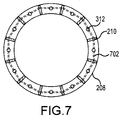
- the lower base plate 208 includes bolt holes 312 formed therein, through which bolts may be inserted to attach the base termination assembly 204 to an underlying surface such as, for example, a concrete termination pad, according to embodiments of the present invention.
- FIG. 5 which illustrates a cross-sectional view of the monopole 202 taken along line A-A of FIG. 4 , shows that the cross section of the monopole may be a polygon with sides 502 of equal length joined by angles 504 of equal magnitude, according to embodiments of the present invention.
- the monopole 202 shell may be a dodecagon with twelve sides 502 and twelve angles 504 , according to embodiments of the present invention.
- FIG. 6 which illustrates a cross-sectional view of the base termination assembly 204 taken along line B-B of FIG. 4 , shows that the bolt holes 312 may be formed at an equal distance from the axial centerline 606 of the monopole 202 , and that the bolt holes 312 may be evenly spaced circumferentially around the lower base plate 208 , according to embodiments of the present invention.
- the web plates 210 may be oriented radially with respect to the axial centerline 606 of the monopole 202 , and connect to the lower base plate 208 at the midpoints between two adjacent bolt holes 312 , according to embodiments of the present invention.
- the lower base plate 208 may be formed as a ring which includes an outer edge 602 and an inner edge 604 , and the bolt holes 312 may be formed in the lower base plate at a midpoint between the outer edge 602 and the inner edge 604 , as depicted in FIG. 6 , according to embodiments of the present invention.
- FIG. 7 illustrates a virtual projection 702 of the monopole 202 through the lower base plate 208 , according to embodiments of the present invention.
- a virtual projection 702 of the monopole 202 illustrates a superimposition of the cross-section of the monopole 202 as depicted in FIG. 5 onto the view of FIG. 6 as if the monopole 202 shell had been extended lengthwise through the upper base plate 206 and lower base plate 208 , according to embodiments of the present invention.
- the virtual projection 702 intersects the bolt holes 312 ; in addition, the corners 504 of the virtual projection 702 intersect the web plates 210 and the bolt holes 312 are intersected by the virtual projection 702 at the midpoint of the sides 502 , according to embodiments of the present invention.
- the bolt holes 312 and thus the bolts placed through them, are therefore in-line with the monopole 202 structure.
- Such a configuration eliminates the moment arm created by placing the bolts at a distance from the monopole 202 shell, and reduces or eliminates warping and fatigue failure of the monopole 202 shell at the base termination location, according to embodiments of the present invention.
- Such a configuration also permits easy access to the bolt hole 312 location for the insertion, removal, tightening, and/or loosening of the bolts, according to embodiments of the present invention.
- the bolt holes 312 may be accessed between adjacent web plates 210 and between the upper base plate 206 and lower base plate 208 , according to embodiments of the present invention.
- FIG. 1B illustrates a perspective view of a monopole 100 in which an access window 112 is formed.
- the access windows between adjacent web plates 210 also permit inspection or other physical access to the inside of the monopole 202 without compromising its structure and/or symmetry.
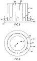
- FIG. 8-10 illustrate an alternative base plate 802 , according to embodiments of the present invention.
- the monopole 202 includes a number of sides 806 of equal length connected at angles 808 of equal magnitude.
- the base plate 802 includes a top surface 810 and a bottom surface 812 , and the top surface 810 is joined to a bottom edge 1002 of the monopole 202 at a base perimeter 814 , according to embodiments of the present invention.
- FIG. 9 illustrates a cross-sectional view of the monopole 850 and the base plate 802 taken along line A-A of FIG. 8 .
- the cross-section of monopole 850 is an octadecagon which includes eighteen sides 806 and eighteen angles 808 .
- the monopole 850 includes bolt windows 804 formed above each of the bolt holes 902 , according to embodiments of the present invention.
- the bolt holes 902 are formed in the base plate 802 and, as seen in FIG. 9 , a virtual projection of the monopole 850 through the base plate 802 intersects each of the bolt holes 902 , according to embodiments of the present invention.
- the base plate 802 includes an outer edge 904 and an inner edge 906 , and the bolt holes 902 are formed in the base plate 802 between the outer edge 904 and inner edge 906 , at an equal radial distance from an axial centerline 908 of the monopole 850 , and evenly circumferentially spaced as shown in FIG. 9 , according to embodiments of the present invention.
- the bolt holes 902 are therefore in-line with the monopole 850 structure.
- Such a configuration eliminates the moment arm created by placing the bolts at a distance from the monopole 850 shell, and reduces warping and fatigue failure at the base termination location, according to embodiments of the present invention.
- Including bolt windows 804 also permits easy access to the bolt hole 902 location for the insertion, removal, tightening, and/or loosening of the bolts, according to embodiments of the present invention.
- the bolt windows 804 may be formed in an arch-shape, a door-shape, or any other shape which permits access to the bolt and/or bolt hole 902 .
- Forming a number of bolt holes 902 in the base plate which corresponds to half the number of sides in the cross-sectional polygon of the monopole 850 permits formation of the bolt windows 804 in every second side 806 , for increased structural stability, according to embodiments of the present invention.
- the bolt windows 804 also provide a portal through which cables and/or wires may be passed. Without such access windows 804 , holes would otherwise need to be created in the side of the monopole 850 , further weakening its structure. According to some embodiments of the present invention, the bolt windows 804 also permit inspection or other physical access to the inside of the monopole 850 without compromising its structure and/or symmetry.
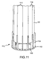
- FIGS. 11 and 12 illustrate an alternative embodiment of a base termination assembly 1112 , according to embodiments of the present invention.
- the monopole 202 shell may be a dodecagon with twelve sides 1108 and twelve angles 1110 , according to embodiments of the present invention.
- Web plates 1104 may be used to join the bottom end 1202 of the monopole 202 with a base plate 1102 , according to embodiments of the present invention.
- Each of the web plates 1104 includes a top end 1204 and a bottom end 1206 , and a notch or groove or longitudinal slot 1208 extends into the web plate 1104 from the top end 1204 , according to embodiments of the present invention.
- the slot 1208 is configured to receive the bottom end 1202 of the monopole 202 .
- the base plate 1102 which includes an outer edge 1210 and an inner edge 1212 , has bolt holes 1106 formed therein.
- FIG. 12 depicts an exploded view of the monopole 202 and base termination assembly 1112 , according to embodiments of the present invention.
- the bottom edge 1212 of the monopole 202 may be inserted into the slots 1208 , and the web plates 1104 may be welded to the monopole 202 along the slots 1208 , according to embodiments of the present invention.
- a cross-sectional view of the base termination assembly 1112 taken below the monopole 202 is much the same as the view of FIG. 6 , according to embodiments of the present invention.
- the bolt holes 1106 may be formed at an equal distance from the axial centerline of the monopole 202 , and the bolt holes 1106 may be evenly spaced circumferentially around the base plate 1102 , according to embodiments of the present invention.
- the web plates 1104 may be oriented radially with respect to the axial centerline of the monopole 202 , and connect to the base plate 1102 at the midpoints between two adjacent bolt holes 1106 , according to embodiments of the present invention.
- the base plate 1102 may be formed as a ring which includes an outer edge 1210 and an inner edge 1212 , and the bolt holes 1106 may be formed in the base plate 1102 at a midpoint between the outer edge 1210 and the inner edge 1212 , according to embodiments of the present invention.
- the virtual projection of the monopole 202 through the base plate 1106 intersects the bolt holes 1106 ; in addition, the corners 1110 of the virtual projection intersect the web plates 1104 and the bolt holes 1106 are intersected by the virtual projection at the midpoint of the sides 1108 , according to embodiments of the present invention.
- the bolt holes 1106 and thus the bolts placed through them, are therefore in-line with the monopole 202 structure.
- Such a configuration eliminates the moment arm created by placing the bolts at a distance from the monopole 202 shell, and reduces warping and fatigue failure at the base termination location, according to embodiments of the present invention.
- Such a configuration also permits easy access to the bolt hole 1106 location for the insertion, removal, tightening, and/or loosening of the bolts, according to embodiments of the present invention.
- the bolt holes 1106 may be accessed between adjacent web plates 1104 and between the bottom edge 1202 of the monopole 202 and the base plate 1102 , according to embodiments of the present invention.
- FIGS. 13-15 illustrate yet another alternative embodiment of the present invention.
- a monopole 202 is joined with a base plate 1302 around a base perimeter 1310 at the top surface 1402 of the base plate 1302 , according to embodiments of the present invention.
- support posts 1304 are joined with the base plate 1302 .
- the base plate 1302 has an outer edge 1502 and an inner edge 1504 , according to embodiments of the present invention.
- the support posts may be configured for joining with support columns 1308 .
- an outer surface of each support post 1304 and each support column 1308 may be configured to threadably engage a connection nut 1306 , as illustrated in FIGS. 13 and 14 .
- the support columns 1308 may be arranged and/or embedded within an underlying surface, such as, for example, a concrete base termination pad.
- the support columns 1308 may be arranged in a pre-formed pattern selected to match the pattern of the support posts 1304 joined to the bottom surface 1404 of the base plate 1302 .
- the monopole 202 with base plate 1302 may then be positioned over the pre-formed pattern of support columns 1308 , and the support posts 1304 may be coupled with the support columns 1308 , such as, for example, by threaded nuts 1306 , according to embodiments of the present invention.
- a virtual projection of each of the support posts 1304 through the base plate 1502 intersects the monopole 202 and the base perimeter 1310 of the monopole 202 , according to embodiments of the present invention.
- the monopole may be a dodecagon with twelve equal sides 1506 and twelve equal corners 1508
- the base plate 1302 may include twelve support posts 1304 each joined to the bottom surface 1404 of the base plate 1302 at a midpoint of each of the sides 1506 , according to embodiments of the present invention.
- Such a configuration places the support posts 1304 in-line with the monopole 202 structure, according to embodiments of the present invention.
- Such a configuration also eliminates the moment arm created by placing the bolts and/or support posts 1304 at a distance from the monopole 202 shell, and reduces warping and fatigue failure at the base termination location, according to embodiments of the present invention.
- Such a configuration also permits easy access to the support posts 1304 for facilitated attachment, detachment, tightening, and/or loosening of the nuts 1306 and/or the support columns 1308 , according to embodiments of the present invention.
- inline base termination embodiments have been discussed in connection with monopole structures which are dodecagons and octadecagons, one of ordinary skill in the art, based on the disclosure herein, will appreciate that similar inline base termination structures may be employed for monopole structures which are round, square, or which have cross sections of varying shapes and sizes, or which have cross sections that are radially asymmetrical, according to embodiments of the present invention.
- the structure components described herein may be made of any suitable material.
- the monopoles, base plates, and web plates may be formed of steel, according to embodiments of the present invention.
- the term “joined” is used in its broadest sense to refer to two elements which are connected. For example, two elements may be joined, coupled, attached, connected, or affixed to one another by welding the two elements together, according to embodiments of the present invention.
- the bolts used for insertion through bolt holes are selected to meet the overturning moment of the monopole shaft 202 , according to embodiments of the present invention.
- the monopole 202 has a diameter of 45.5 inches (bolt circle, B C ); that the number of bolts equals the number of sides which also equals the number of web plates 210 , which equals eighteen; that the same geometry will be used for the top and bottom base plates 206 , 208 ; that the base plates 206 , 208 are separated by twelve inches; that the monopole wall 202 is three-eighths inches thick; that M max , the maximum moment experienced by the monopole 202 , is 2145.1 kip-feet; and that the maximum axial force F A of the monopole 202 is 20.5 kip; the following procedure may be used to select anchor bolts, the width and thickness of the top and bottom base plates 206 , 208 , and the spacing and thickness of the web plates 210 .
- T max ⁇ ⁇ AB 4 ⁇ M max ⁇ 12 £ ⁇ ⁇ ofbolts ⁇ B C ⁇ F A £ ⁇ ⁇ ofbolts ( Eq . ⁇ 1 )
- the required bolt area, AE may be found with the following equation:
- n is equal to the number of threads per inch, and which for purposes of this example is assumed to be equal to 4.5. Using these values, F AB is found to be 1.86 inches. Rounding up to the nearest quarter inch, the bolt diameter may be selected as 2.0 inches.
- the width b of the top and bottom base plates 206 , 208 between the outer 602 and inner 604 diameter may be found with the following equation:
- the circumferential spacing L of the web plates 210 may be found with the following equation:
- the circumferential spacing of the web plates is 7.94 inches, according to the particular example described.
- the thickness h BP of the top 206 and bottom 208 base plates may be determined with the following equation:
- h BP 3 ⁇ T max ⁇ ⁇ AB ⁇ L 4 ⁇ b ⁇ F yPL ⁇ [ USDfactor ] ⁇ 0.6 ( Eq . ⁇ 6 )
- web plates 210 which are oriented radially with respect to the axial centerline 606 of the monopole 202 (see FIG. 6 )
- the web plates 210 may be oriented at an angle with respect to a radius of the base plate 208 .
- the web plates 210 may be oriented at an angle of ten degrees with respect to a radius of the base plate 208 , while still providing similar support characteristics and access to the inside of the monopole 202 , according to embodiments of the present invention.
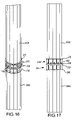
- a base termination assembly 204 may also be used to splice a termination end of one monopole section 202 a with a termination end of another monopole section 202 b , according to embodiments of the present invention.
- Such a configuration may be used to add an additional monopole section 202 b onto an existing monopole 202 a , and/or to assemble a monopole which has been prefabricated in sections 202 a , 202 b , according to embodiments of the present invention.
- a base termination assembly 204 may be joined to one of the monopole sections 202 a , and another base termination assembly may be joined to the other monopole section 202 b , and the base plates 208 of each base termination assembly 204 may be bolted together using bolts 1602 , according to embodiments of the present invention.
Landscapes
- Engineering & Computer Science (AREA)
- Architecture (AREA)
- Structural Engineering (AREA)
- Civil Engineering (AREA)
- Materials Engineering (AREA)
- Wood Science & Technology (AREA)
- Life Sciences & Earth Sciences (AREA)
- Chemical & Material Sciences (AREA)
- Connection Of Plates (AREA)
- Measuring Leads Or Probes (AREA)
- Chemically Coating (AREA)
- Stringed Musical Instruments (AREA)
- Bridges Or Land Bridges (AREA)
Abstract
Description
- Embodiments of the present invention relate generally to monopole structures, and more particularly to end termination support and section splices for monopole structures.
- Monopole structures typically house antennae and other communications equipment. Such structures often include a long, hollow pole structure which is connected to an underlying surface such as a concrete pad formed in the ground. Monopole structures are also used for other purposes, such as, for example, light fixtures, flag poles, and utility poles. As such, monopole structures are typically subjected to wind or other types of forces along their length, which bend or sway the monopole structures. These forces create a torque about the base termination, which in turn stresses the base termination location and can lead to fatigue and eventual failure of the base termination material.
- Current monopole structures are often connected to an underlying concrete pad via a base termination plate with one or more flanges which protrude from the monopole structure. Bolts are often placed through the protruding flange of the base termination plate, and secured to the underlying pad. Placement of the bolts at a radial distance from the outside of the monopole structure (e.g. eccentric loading) enhances the torque experienced by the termination plate, increasing the stress distribution on the pole shaft just above the weld line. This secondary moment causing fatigue in the pole shaft can lead to a shorter life span with a higher risk of cracking at the welds and ultimate failure.
- An inline base plate termination system according to embodiments of the present invention includes an upper base plate configured to be joined to a bottom end of a monopole, a lower base plate substantially parallel to the upper base plate, the lower base plate having a plurality of bolt holes, and a plurality of web plates connecting the upper base plate with the lower base plate, wherein a virtual projection of the monopole through the lower base plate intersects the plurality of bolt holes. According to some embodiments of the present invention, each of the plurality of web plates is oriented radially with respect to an axial centerline of the monopole, and each of the plurality of bolt holes may be formed in the lower base plate at an equal distance from the axial centerline and evenly spaced circumferentially around the lower base plate. In some cases, each of the plurality of web plates connects to the lower base plate at a midpoint between two adjacent bolt holes of the plurality of bolt holes. In some instances, the monopole is hollow.
- According to some embodiments of the present invention, the upper base plate may be joined to the bottom end of the monopole at a base perimeter, and a virtual projection of the base perimeter through the base plate intersects the plurality of bolt holes. According to other embodiments of the present invention, the virtual projection of the monopole through the lower base plate intersects a centerline of each of the plurality of bolt holes. In some cases, a cross section of the monopole may be a dodecagon with twelve sides of equal length joined at twelve angles of equal magnitude, the plurality of bolt holes is twelve bolt holes, the plurality of web plates is twelve web plates, and the virtual projection of the monopole through the lower base plate intersects each of the twelve web plates at one of the twelve angles and intersects each of the twelve bolt holes at a midpoint of one of the twelve sides. In other cases, a cross section of the monopole may be a polygon with sides of equal length joined at angles of equal magnitude, and the virtual projection of the monopole through the lower base plate intersects each of the plurality of web plates at one of the angles and intersects each of the plurality of bolt holes at a midpoint of one of the sides.
- In some instances of the embodiments, the lower base plate is a circular ring with an outer edge and an inner edge, and each of the plurality of bolt holes is formed at a midpoint between the outer edge and the inner edge. Some embodiments of the present invention include an additional upper base plate configured to be joined to a top end of an additional monopole, an additional lower base plate substantially parallel to the additional upper base plate and including an additional plurality of bolt holes, an additional plurality of web plates connecting the additional upper base plate with the additional lower base plate, and an additional plurality of bolts connecting the first lower base plate with the additional lower base plate, such that the virtual projection also intersects the additional plurality of bolt holes.
- Methods for monopole termination according to embodiments of the present invention include joining a monopole to an upper base plate, forming a plurality of bolt holes in a lower base plate, each of the plurality of bolt holes formed at an equal radial distance from a central axis of the monopole, and each of the plurality of bolt holes substantially evenly circumferentially spaced, joining each of a plurality of web plates to the lower base plate and the upper base plate, each of the plurality of web plates affixed to the lower base plate between two adjacent bolt holes of the plurality of bolt holes, and placing bolts through the plurality of bolt holes to join the lower base plate with a base platform, such that a virtual projection of the monopole through the lower base plate intersects the plurality of bolt holes. Methods according to such embodiments may further include deploying a cable through an access window between two adjacent web plates of the plurality of web plates and between the upper base plate and the lower base plate.
- An inline base plate termination system according to embodiments of the present invention includes a monopole, a base plate joined to the monopole at a base perimeter, bolt holes formed in the base plate, the base perimeter intersecting the bolt holes, and bolt windows formed in the monopole over each of the bolt holes, the bolt windows permitting access to the bolt holes for insertion, removal, tightening, or loosening of bolts. An inline base plate termination system according to other embodiments of the present invention includes a monopole, a base plate having a top surface and a bottom surface, the top surface joined to the monopole at a base perimeter, and a plurality of support posts joined to the bottom surface, wherein a virtual projection of each of the plurality of support posts through the base plate intersects the base perimeter. An inline base plate termination system according to yet other embodiments of the present invention includes a hollow monopole having an outer shell, a base plate having a plurality of bolt holes formed therein, the plurality of bolt holes formed in a circular pattern and evenly circumferentially spaced, and a plurality of web plates, each of the plurality of web plates having an upper end and a lower end, the upper end having a longitudinal slot configured to receive and join with a bottom portion of the outer shell, the lower end joined to the base plate between two adjacent bolt holes of the plurality of bolt holes, wherein a virtual projection of the hollow monopole through the base plate intersects the plurality of bolt holes.
- While multiple embodiments are disclosed, still other embodiments of the present invention will become apparent to those skilled in the art from the following detailed description, which shows and describes illustrative embodiments of the invention. Accordingly, the drawings and detailed description are to be regarded as illustrative in nature and not restrictive.
-
FIG. 1A illustrates a front elevation view of a monopole structure with an existing base plate termination. -
FIG. 1B illustrates a front perspective view of a monopole structure with an access port formed therein. -
FIG. 2 illustrates a front elevation view of a monopole structure with an inline base termination assembly, according to embodiments of the present invention. -
FIG. 3 illustrates an exploded view of the monopole structure with inline base termination assembly ofFIG. 2 , according to embodiments of the present invention. -
FIG. 4 illustrates a front elevation view of a monopole structure with an inline base termination assembly, according to embodiments of the present invention. -
FIG. 5 illustrates a top cross-sectional view of the monopole structure ofFIG. 4 taken along line A-A ofFIG. 4 , according to embodiments of the present invention. -
FIG. 6 illustrates a top cross-sectional view of the base termination assembly ofFIG. 4 taken along line B-B ofFIG. 4 , according to embodiments of the present invention. -
FIG. 7 illustrates the top cross-sectional view ofFIG. 6 with a virtual projection of the monopole, according to embodiments of the present invention. -
FIG. 8 illustrates a front elevation view of a monopole with an alternative base termination, according to embodiments of the present invention. -
FIG. 9 illustrates a top cross-sectional view of the monopole with alternative base termination ofFIG. 8 , taken along line A-A ofFIG. 8 , according to embodiments of the present invention. -
FIG. 10 illustrates an exploded perspective view of the monopole with alternative base termination ofFIGS. 8 and 9 , according to embodiments of the present invention. -
FIG. 11 illustrates a front perspective view of a monopole with yet another alternative embodiment of an inline base termination assembly, according to embodiments of the present invention. -
FIG. 12 illustrates an exploded front perspective view of the monopole and inline base termination assembly ofFIG. 11 , according to embodiments of the present invention. -
FIG. 13 illustrates a front perspective view of a monopole with an additional alternative embodiment of an inline base termination, according to embodiments of the present invention. -
FIG. 14 illustrates a front elevation view of the monopole and inline base termination ofFIG. 13 , according to embodiments of the present invention. -
FIG. 15 illustrates a top cross-sectional view of the monopole and base plate ofFIG. 14 , taken along line A-A ofFIG. 14 , according to embodiments of the present invention. -
FIG. 16 illustrates a front perspective view of a dual base termination assembly splicing together two monopole sections, according to embodiments of the present invention. -
FIG. 17 illustrates a front elevation view of the dual base termination assembly ofFIG. 16 . - While the invention is amenable to various modifications and alternative forms, specific embodiments have been shown by way of example in the drawings and are described in detail below. The intention, however, is not to limit the invention to the particular embodiments described. On the contrary, the invention is intended to cover all modifications, equivalents, and alternatives falling within the scope of the invention as defined by the appended claims.
-
FIG. 1 depicts atypical monopole structure 100 which is affixed to an existingbase plate 102.Bolts 106 are placed through thebase plate 102 and into theunderlying base pad 108 at a distance 104 from theouter edge 110 of themonopole 100. This distance 104 enhances the torque experienced by thebase plate 102 between thebolt 106 and theouter edge 110 due to lateral forces (e.g. wind) experienced by themonopole 100. This, in turn, often leads to warping and/or failure of the base of themonopole shell 110 over time at that location. However, thebolts 106 must be placed at a distance 104 from theouter edge 100 in such designs to permit adequate access for insertion, removal, tightening, and loosening of thebolts 106. -
FIGS. 2-7 illustrate amonopole 202 with abase termination assembly 204, according to embodiments of the present invention. As seen inFIGS. 2 and 3 , thebase termination assembly 204 includes anupper base plate 206 and alower base plate 208 which are connected byweb plates 210, according to embodiments of the present invention. Themonopole 202 includes atop end 304 and abottom end 302. Thetop side 306 of theupper base plate 206 is joined with thebottom end 302 of the monopole such as, for example, by welding, according to embodiments of the present invention. Each of theweb plates 210 includes atop end 308 and abottom end 310, with thetop end 308 joined (e.g. welded) to the bottom side (not shown) of theupper base plate 206 and thebottom end 310 joined (e.g. welded) to thelower base plate 208, according to embodiments of the present invention. Thelower base plate 208 includes bolt holes 312 formed therein, through which bolts may be inserted to attach thebase termination assembly 204 to an underlying surface such as, for example, a concrete termination pad, according to embodiments of the present invention. - As shown in
FIGS. 4-6 , themonopole 202 is joined to theupper base plate 206 at abase perimeter 402.FIG. 5 , which illustrates a cross-sectional view of themonopole 202 taken along line A-A ofFIG. 4 , shows that the cross section of the monopole may be a polygon withsides 502 of equal length joined byangles 504 of equal magnitude, according to embodiments of the present invention. For example, as depicted inFIG. 5 , themonopole 202 shell may be a dodecagon with twelvesides 502 and twelveangles 504, according to embodiments of the present invention. -
FIG. 6 , which illustrates a cross-sectional view of thebase termination assembly 204 taken along line B-B ofFIG. 4 , shows that the bolt holes 312 may be formed at an equal distance from theaxial centerline 606 of themonopole 202, and that the bolt holes 312 may be evenly spaced circumferentially around thelower base plate 208, according to embodiments of the present invention. Similarly, theweb plates 210 may be oriented radially with respect to theaxial centerline 606 of themonopole 202, and connect to thelower base plate 208 at the midpoints between two adjacent bolt holes 312, according to embodiments of the present invention. Such a radially-symmetrical and evenly-spaced configuration for the bolt holes 312 and/or theweb plates 210 imparts a higher degree of performance with concentric loading when compared to non-symmetrical and/or non-evenly spaced configurations. Thelower base plate 208 may be formed as a ring which includes anouter edge 602 and aninner edge 604, and the bolt holes 312 may be formed in the lower base plate at a midpoint between theouter edge 602 and theinner edge 604, as depicted inFIG. 6 , according to embodiments of the present invention. -
FIG. 7 illustrates avirtual projection 702 of themonopole 202 through thelower base plate 208, according to embodiments of the present invention. Though not a literal projection or extension, avirtual projection 702 of themonopole 202 illustrates a superimposition of the cross-section of themonopole 202 as depicted inFIG. 5 onto the view ofFIG. 6 as if themonopole 202 shell had been extended lengthwise through theupper base plate 206 andlower base plate 208, according to embodiments of the present invention. - As can be seen in
FIG. 7 , thevirtual projection 702 intersects the bolt holes 312; in addition, thecorners 504 of thevirtual projection 702 intersect theweb plates 210 and the bolt holes 312 are intersected by thevirtual projection 702 at the midpoint of thesides 502, according to embodiments of the present invention. The bolt holes 312, and thus the bolts placed through them, are therefore in-line with themonopole 202 structure. Such a configuration eliminates the moment arm created by placing the bolts at a distance from themonopole 202 shell, and reduces or eliminates warping and fatigue failure of themonopole 202 shell at the base termination location, according to embodiments of the present invention. Such a configuration also permits easy access to thebolt hole 312 location for the insertion, removal, tightening, and/or loosening of the bolts, according to embodiments of the present invention. The bolt holes 312 may be accessed betweenadjacent web plates 210 and between theupper base plate 206 andlower base plate 208, according to embodiments of the present invention. - The
bolt hole 312 access windows of thebase termination assembly 204 also provide a portal through which cables and/or wires may be passed. Without such access windows, holes would otherwise need to be created in the side of themonopole 202, further weakening its structure.FIG. 1B illustrates a perspective view of amonopole 100 in which anaccess window 112 is formed. According to some embodiments of the present invention, the access windows betweenadjacent web plates 210 also permit inspection or other physical access to the inside of themonopole 202 without compromising its structure and/or symmetry. -
FIG. 8-10 illustrate analternative base plate 802, according to embodiments of the present invention. Themonopole 202 includes a number ofsides 806 of equal length connected atangles 808 of equal magnitude. Thebase plate 802 includes atop surface 810 and abottom surface 812, and thetop surface 810 is joined to abottom edge 1002 of themonopole 202 at abase perimeter 814, according to embodiments of the present invention. -
FIG. 9 illustrates a cross-sectional view of themonopole 850 and thebase plate 802 taken along line A-A ofFIG. 8 . The cross-section ofmonopole 850, as depicted, is an octadecagon which includes eighteensides 806 and eighteenangles 808. Themonopole 850 includesbolt windows 804 formed above each of the bolt holes 902, according to embodiments of the present invention. The bolt holes 902 are formed in thebase plate 802 and, as seen inFIG. 9 , a virtual projection of themonopole 850 through thebase plate 802 intersects each of the bolt holes 902, according to embodiments of the present invention. Thebase plate 802 includes anouter edge 904 and aninner edge 906, and the bolt holes 902 are formed in thebase plate 802 between theouter edge 904 andinner edge 906, at an equal radial distance from anaxial centerline 908 of themonopole 850, and evenly circumferentially spaced as shown inFIG. 9 , according to embodiments of the present invention. - The bolt holes 902, and thus the bolts placed through them, are therefore in-line with the
monopole 850 structure. Such a configuration eliminates the moment arm created by placing the bolts at a distance from themonopole 850 shell, and reduces warping and fatigue failure at the base termination location, according to embodiments of the present invention. Includingbolt windows 804 also permits easy access to thebolt hole 902 location for the insertion, removal, tightening, and/or loosening of the bolts, according to embodiments of the present invention. Thebolt windows 804 may be formed in an arch-shape, a door-shape, or any other shape which permits access to the bolt and/orbolt hole 902. Forming a number of bolt holes 902 in the base plate which corresponds to half the number of sides in the cross-sectional polygon of themonopole 850 permits formation of thebolt windows 804 in everysecond side 806, for increased structural stability, according to embodiments of the present invention. - The
bolt windows 804 also provide a portal through which cables and/or wires may be passed. Withoutsuch access windows 804, holes would otherwise need to be created in the side of themonopole 850, further weakening its structure. According to some embodiments of the present invention, thebolt windows 804 also permit inspection or other physical access to the inside of themonopole 850 without compromising its structure and/or symmetry. -
FIGS. 11 and 12 illustrate an alternative embodiment of abase termination assembly 1112, according to embodiments of the present invention. Themonopole 202 shell may be a dodecagon with twelvesides 1108 and twelveangles 1110, according to embodiments of the present invention.Web plates 1104 may be used to join thebottom end 1202 of themonopole 202 with abase plate 1102, according to embodiments of the present invention. Each of theweb plates 1104 includes atop end 1204 and abottom end 1206, and a notch or groove orlongitudinal slot 1208 extends into theweb plate 1104 from thetop end 1204, according to embodiments of the present invention. Theslot 1208 is configured to receive thebottom end 1202 of themonopole 202. Thebase plate 1102, which includes anouter edge 1210 and aninner edge 1212, hasbolt holes 1106 formed therein. -
FIG. 12 depicts an exploded view of themonopole 202 andbase termination assembly 1112, according to embodiments of the present invention. Thebottom edge 1212 of themonopole 202 may be inserted into theslots 1208, and theweb plates 1104 may be welded to themonopole 202 along theslots 1208, according to embodiments of the present invention. - A cross-sectional view of the
base termination assembly 1112 taken below themonopole 202 is much the same as the view ofFIG. 6 , according to embodiments of the present invention. The bolt holes 1106 may be formed at an equal distance from the axial centerline of themonopole 202, and the bolt holes 1106 may be evenly spaced circumferentially around thebase plate 1102, according to embodiments of the present invention. Similarly, theweb plates 1104 may be oriented radially with respect to the axial centerline of themonopole 202, and connect to thebase plate 1102 at the midpoints between twoadjacent bolt holes 1106, according to embodiments of the present invention. Such a radially-symmetrical and evenly-spaced configuration for the bolt holes 1106 and/or theweb plates 1104 imparts a higher degree of performance when compared to non-symmetrical and/or non-evenly spaced configurations. Thebase plate 1102 may be formed as a ring which includes anouter edge 1210 and aninner edge 1212, and the bolt holes 1106 may be formed in thebase plate 1102 at a midpoint between theouter edge 1210 and theinner edge 1212, according to embodiments of the present invention. - As in
FIG. 6 , the virtual projection of themonopole 202 through thebase plate 1106 intersects the bolt holes 1106; in addition, thecorners 1110 of the virtual projection intersect theweb plates 1104 and the bolt holes 1106 are intersected by the virtual projection at the midpoint of thesides 1108, according to embodiments of the present invention. The bolt holes 1106, and thus the bolts placed through them, are therefore in-line with themonopole 202 structure. Such a configuration eliminates the moment arm created by placing the bolts at a distance from themonopole 202 shell, and reduces warping and fatigue failure at the base termination location, according to embodiments of the present invention. Such a configuration also permits easy access to thebolt hole 1106 location for the insertion, removal, tightening, and/or loosening of the bolts, according to embodiments of the present invention. The bolt holes 1106 may be accessed betweenadjacent web plates 1104 and between thebottom edge 1202 of themonopole 202 and thebase plate 1102, according to embodiments of the present invention. -
FIGS. 13-15 illustrate yet another alternative embodiment of the present invention. Amonopole 202 is joined with abase plate 1302 around abase perimeter 1310 at thetop surface 1402 of thebase plate 1302, according to embodiments of the present invention. On thebottom surface 1404 of thebase plate 1302,support posts 1304 are joined with thebase plate 1302. Thebase plate 1302 has anouter edge 1502 and an inner edge 1504, according to embodiments of the present invention. The support posts may be configured for joining withsupport columns 1308. For example, an outer surface of eachsupport post 1304 and eachsupport column 1308 may be configured to threadably engage aconnection nut 1306, as illustrated inFIGS. 13 and 14 . - According to some embodiments of the present invention, the
support columns 1308 may be arranged and/or embedded within an underlying surface, such as, for example, a concrete base termination pad. Thesupport columns 1308 may be arranged in a pre-formed pattern selected to match the pattern of thesupport posts 1304 joined to thebottom surface 1404 of thebase plate 1302. Themonopole 202 withbase plate 1302 may then be positioned over the pre-formed pattern ofsupport columns 1308, and the support posts 1304 may be coupled with thesupport columns 1308, such as, for example, by threaded nuts 1306, according to embodiments of the present invention. - As illustrated in
FIG. 15 , a virtual projection of each of the support posts 1304 through thebase plate 1502 intersects themonopole 202 and thebase perimeter 1310 of themonopole 202, according to embodiments of the present invention. As depicted inFIG. 15 , the monopole may be a dodecagon with twelveequal sides 1506 and twelveequal corners 1508, and thebase plate 1302 may include twelvesupport posts 1304 each joined to thebottom surface 1404 of thebase plate 1302 at a midpoint of each of thesides 1506, according to embodiments of the present invention. Such a configuration places thesupport posts 1304 in-line with themonopole 202 structure, according to embodiments of the present invention. Such a configuration also eliminates the moment arm created by placing the bolts and/orsupport posts 1304 at a distance from themonopole 202 shell, and reduces warping and fatigue failure at the base termination location, according to embodiments of the present invention. Such a configuration also permits easy access to thesupport posts 1304 for facilitated attachment, detachment, tightening, and/or loosening of thenuts 1306 and/or thesupport columns 1308, according to embodiments of the present invention. - Although inline base termination embodiments have been discussed in connection with monopole structures which are dodecagons and octadecagons, one of ordinary skill in the art, based on the disclosure herein, will appreciate that similar inline base termination structures may be employed for monopole structures which are round, square, or which have cross sections of varying shapes and sizes, or which have cross sections that are radially asymmetrical, according to embodiments of the present invention. The structure components described herein may be made of any suitable material. For example, the monopoles, base plates, and web plates may be formed of steel, according to embodiments of the present invention. As used herein, the term “joined” is used in its broadest sense to refer to two elements which are connected. For example, two elements may be joined, coupled, attached, connected, or affixed to one another by welding the two elements together, according to embodiments of the present invention.
- The bolts used for insertion through bolt holes are selected to meet the overturning moment of the
monopole shaft 202, according to embodiments of the present invention. For example, assuming that themonopole 202 has a diameter of 45.5 inches (bolt circle, BC); that the number of bolts equals the number of sides which also equals the number ofweb plates 210, which equals eighteen; that the same geometry will be used for the top andbottom base plates base plates monopole wall 202 is three-eighths inches thick; that Mmax, the maximum moment experienced by themonopole 202, is 2145.1 kip-feet; and that the maximum axial force FA of themonopole 202 is 20.5 kip; the following procedure may be used to select anchor bolts, the width and thickness of the top andbottom base plates web plates 210. The maximum tension on the anchor bolts, TmaxAB, may be found with the following equation: -
- Solving the equation with the above-referenced values yields a solution of 126.84 kips or 124.56 kips, the higher of which is used to determine the required bolt size, according to embodiments of the present invention. The required bolt area, AE, may be found with the following equation:
-
- Assuming a USDfactor of 1.333 and a value for FyAB of 75 ksi yields a result for AE of 2.11 square inches. The bolt diameter FAB required may be found with the following equation:
-
- where n is equal to the number of threads per inch, and which for purposes of this example is assumed to be equal to 4.5. Using these values, FAB is found to be 1.86 inches. Rounding up to the nearest quarter inch, the bolt diameter may be selected as 2.0 inches.
- Continuing the example, the width b of the top and
bottom base plates -
b=F AB+2(F AB) (Eq. 4) - which results in a value for b of 6.0 inches. The circumferential spacing L of the
web plates 210 may be found with the following equation: -
- Thus, the circumferential spacing of the web plates is 7.94 inches, according to the particular example described. The thickness hBP of the top 206 and bottom 208 base plates may be determined with the following equation:
-
- where FyPL is assumed to be 50 ksi yield, which results in a value for hBP of 1.77 inches. Rounded up to the nearest quarter inch, hBP is equal to 2.0 inches. The thickness hST of the
web plates 210 may be found with the following equation: -
- where the bending factor in compression, Bfactor, is assumed to be 1.75. Using the values from above results in a value for hST of 0.93 inches which, rounded up to the nearest eighth inch, is 1.0 inches. Based on the disclosure provided herein, one of ordinary skill in the art will appreciate the various sizes and configurations that may be used for the
base plates web plates 210, according to embodiments of the present invention. - Although some embodiments of the present invention are described with respect to
web plates 210 which are oriented radially with respect to theaxial centerline 606 of the monopole 202 (seeFIG. 6 ), one of ordinary skill in the art, based on the disclosure provided herein, will appreciate that theweb plates 210 may be oriented at an angle with respect to a radius of thebase plate 208. For example, theweb plates 210 may be oriented at an angle of ten degrees with respect to a radius of thebase plate 208, while still providing similar support characteristics and access to the inside of themonopole 202, according to embodiments of the present invention. - As illustrated in
FIGS. 16 and 17 , abase termination assembly 204 may also be used to splice a termination end of onemonopole section 202 a with a termination end of anothermonopole section 202 b, according to embodiments of the present invention. Such a configuration may be used to add anadditional monopole section 202 b onto an existingmonopole 202 a, and/or to assemble a monopole which has been prefabricated insections base termination assembly 204 may be joined to one of themonopole sections 202 a, and another base termination assembly may be joined to theother monopole section 202 b, and thebase plates 208 of eachbase termination assembly 204 may be bolted together usingbolts 1602, according to embodiments of the present invention. - Various modifications and additions can be made to the exemplary embodiments discussed without departing from the scope of the present invention. For example, while the embodiments described above refer to particular features, the scope of this invention also includes embodiments having different combinations of features and embodiments that do not include all of the described features. Accordingly, the scope of the present invention is intended to embrace all such alternatives, modifications, and variations as fall within the scope of the claims, together with all equivalents thereof.
Claims (22)
Priority Applications (2)
| Application Number | Priority Date | Filing Date | Title |
|---|---|---|---|
| US12/040,799 US7694476B2 (en) | 2008-02-29 | 2008-02-29 | Systems and methods for in-line base plate termination in monopole structures |
| PCT/US2009/035098 WO2009111236A2 (en) | 2008-02-29 | 2009-02-25 | Systems and methods for in-line base plate termination in monopole structures |
Applications Claiming Priority (1)
| Application Number | Priority Date | Filing Date | Title |
|---|---|---|---|
| US12/040,799 US7694476B2 (en) | 2008-02-29 | 2008-02-29 | Systems and methods for in-line base plate termination in monopole structures |
Publications (2)
| Publication Number | Publication Date |
|---|---|
| US20090217618A1 true US20090217618A1 (en) | 2009-09-03 |
| US7694476B2 US7694476B2 (en) | 2010-04-13 |
Family
ID=41012109
Family Applications (1)
| Application Number | Title | Priority Date | Filing Date |
|---|---|---|---|
| US12/040,799 Expired - Fee Related US7694476B2 (en) | 2008-02-29 | 2008-02-29 | Systems and methods for in-line base plate termination in monopole structures |
Country Status (2)
| Country | Link |
|---|---|
| US (1) | US7694476B2 (en) |
| WO (1) | WO2009111236A2 (en) |
Cited By (9)
| Publication number | Priority date | Publication date | Assignee | Title |
|---|---|---|---|---|
| WO2012122976A3 (en) * | 2011-03-14 | 2012-11-15 | Ed. Züblin Ag | Device and method for the transition between a steel tower section and a pre-stressed concrete tower section |
| US20130129525A1 (en) * | 2009-11-16 | 2013-05-23 | Wilic S.Ar.L. | Wind power plant for producing electric energy, and relative pylon construction method |
| BE1023021B1 (en) * | 2015-12-04 | 2016-11-07 | Ptm Engineering Bvba | Method for reinforcing telecommunication masts |
| US10041269B2 (en) * | 2015-04-02 | 2018-08-07 | Arcelormittal | Wind turbine tower section, wind turbine tower and assembly method |
| US10563419B2 (en) * | 2015-07-09 | 2020-02-18 | Vensys Energy Ag | Tower for a wind power plant |
| WO2021071641A1 (en) * | 2019-10-07 | 2021-04-15 | Commscope Technologies Llc | Telecommunications antenna mounts and associated transition covers |
| US20240318635A1 (en) * | 2021-06-30 | 2024-09-26 | Vestas Wind Systems A/S | Transition piece for a hybrid wind turbine tower and method for assembling same |
| WO2025051450A1 (en) * | 2023-09-05 | 2025-03-13 | Siemens Gamesa Renewable Energy A/S | A tower for a wind turbine |
| US12338644B1 (en) * | 2023-12-21 | 2025-06-24 | Gary Barbosa | Apparatus for mounting cellular tower on billboards |
Families Citing this family (12)
| Publication number | Priority date | Publication date | Assignee | Title |
|---|---|---|---|---|
| US20100071771A1 (en) * | 2007-04-18 | 2010-03-25 | Searete Llc, A Limited Liability Corporation Of The State Of Delaware | High altitude atmospheric injection system and method |
| ES2330482T3 (en) * | 2007-06-20 | 2009-12-10 | Siemens Aktiengesellschaft | TOWER OF WIND TURBINE AND METHOD TO BUILD A TOWER OF WIND TURBINE. |
| US8074955B2 (en) * | 2008-07-07 | 2011-12-13 | Cooper Technologies Company | Method and apparatus for improving the strength of a utility pole |
| US20100024311A1 (en) * | 2008-07-30 | 2010-02-04 | Dustin Jon Wambeke | Wind turbine assembly with tower mount |
| US8220214B1 (en) * | 2009-05-02 | 2012-07-17 | Purdy Charles L | Prefabricated weight distribution element |
| TWI404265B (en) * | 2009-05-05 | 2013-08-01 | Univ Nat Chiao Tung | Printed dipole antenna and its manufacturing method |
| US8302357B1 (en) * | 2010-10-26 | 2012-11-06 | Kontek Industries, Inc. | Blast-resistant foundations |
| DE102011080824A1 (en) * | 2011-08-11 | 2013-02-14 | Mahle International Gmbh | Plate heat exchanger |
| KR101309685B1 (en) | 2012-01-19 | 2013-09-17 | 김인경 | Pallet |
| KR101309686B1 (en) | 2012-01-19 | 2013-09-17 | 김인경 | Pallet |
| US10487907B1 (en) * | 2016-05-10 | 2019-11-26 | Valmont Industries Inc. | Bracket arrangement for supporting the weld area of a pole |
| USD887026S1 (en) | 2018-04-12 | 2020-06-09 | P4 Infrastructure, Inc. | Mast base connector |
Citations (37)
| Publication number | Priority date | Publication date | Assignee | Title |
|---|---|---|---|---|
| US2181196A (en) * | 1936-07-08 | 1939-11-28 | Babecock & Wilcox Company | Composite flange structure |
| US3345096A (en) * | 1965-08-23 | 1967-10-03 | Kubota Ltd | Building column and beam joint construction |
| US3410995A (en) * | 1965-02-24 | 1968-11-12 | James F. Gray | Upright, sectional, tubular support standard |
| US3571991A (en) * | 1969-02-06 | 1971-03-23 | Anderson Electric Corp | Metal pole |
| US3837752A (en) * | 1973-01-26 | 1974-09-24 | J Shewchuk | Coupling for break away pole bases |
| US3861098A (en) * | 1970-07-10 | 1975-01-21 | Karl Schaub | Spacer disk for the production of a floor covering |
| US3977531A (en) * | 1973-05-03 | 1976-08-31 | Sam P. Wallace Company, Inc. | Stiff-leg crane |
| US4048776A (en) * | 1972-08-21 | 1977-09-20 | Kajima Corporation | Steel column base member |
| US4053082A (en) * | 1976-03-01 | 1977-10-11 | Unarco Industries, Inc. | Electrical outlet box assembly |
| US4079559A (en) * | 1976-11-01 | 1978-03-21 | Kim Lighting, Inc. | Hinged base for lighting pole |
| US4228627A (en) * | 1979-04-16 | 1980-10-21 | Neill Joseph C O | Reinforced foundation structure |
| US4269010A (en) * | 1979-11-21 | 1981-05-26 | Glass Carl R | Multi fin post anchor system |
| US4295308A (en) * | 1979-10-26 | 1981-10-20 | K S L Corporation | Pole base assembly, bolt circle adaptor |
| USD273712S (en) * | 1981-11-17 | 1984-05-01 | Claes Ahlqvist | Base for a column |
| US4649675A (en) * | 1985-11-12 | 1987-03-17 | M/A-Com | Nonpenetrating roof mount for antenna |
| US4674907A (en) * | 1985-05-14 | 1987-06-23 | John Shewchuk | Coupling component for breakaway pole bases |
| US5054135A (en) * | 1989-12-15 | 1991-10-08 | Vogue Industries Ltd. | Above ground pool |
| US5333436A (en) * | 1992-09-14 | 1994-08-02 | Pirod, Inc. | Modular antenna pole |
| US5568909A (en) * | 1995-03-10 | 1996-10-29 | Timko; Robert J. | Mounting bracket |
| US5687537A (en) * | 1996-05-24 | 1997-11-18 | Pi Rod Inc. | Modular antenna pole |
| US5771093A (en) * | 1997-02-11 | 1998-06-23 | Trw Inc. | Mounting platform for optical system |
| US5819487A (en) * | 1997-03-13 | 1998-10-13 | Ameron International Corporation | Prestressed concrete poles with internal bolting and leveling structures |
| US20020056250A1 (en) * | 2000-04-24 | 2002-05-16 | Cash David W. | Method and apparatus for increasing the capacity and stability of a single-pole tower |
| US6453636B1 (en) * | 2000-04-24 | 2002-09-24 | Charles D. Ritz | Method and apparatus for increasing the capacity and stability of a single-pole tower |
| US6467811B2 (en) * | 2000-08-10 | 2002-10-22 | Omega Multi National | Flanged connection repair device and method |
| US20040031902A1 (en) * | 2000-01-20 | 2004-02-19 | Universal Support Systems Llc | Support apparatus |
| US20040194402A1 (en) * | 2003-04-01 | 2004-10-07 | Payne Calvin J. | Tower monopole reinforcement |
| US20040211148A1 (en) * | 1999-02-12 | 2004-10-28 | Newmark International, Inc. | Multiple-part pole |
| US6820389B1 (en) * | 2003-03-20 | 2004-11-23 | Valmont Industries, Inc. | Support pole having a traffic signal support arm attached thereto |
| US6857808B1 (en) * | 1999-08-26 | 2005-02-22 | Nippon Steel Corporation | Joining structure |
| US20050056741A1 (en) * | 2002-07-04 | 2005-03-17 | Kee Klamp Limited | Modular safety rail system |
| US6873303B2 (en) * | 2000-09-21 | 2005-03-29 | Barry Roger Creighton | Telecommunications mast installation |
| US6901717B2 (en) * | 2001-05-16 | 2005-06-07 | Pennsummit Tubular, Llc | Pole reinforcing arrangement |
| US6910666B2 (en) * | 2001-10-12 | 2005-06-28 | William J. Burr | Adjustable leveling mount |
| US20050225087A1 (en) * | 2002-05-02 | 2005-10-13 | Tyco Water Pty Limited | Pipe coupling |
| US7098864B2 (en) * | 2003-05-23 | 2006-08-29 | Creative Design And Machining, Inc. | Temporary cellular antenna site |
| US20060232490A1 (en) * | 2003-06-26 | 2006-10-19 | Andrew Corporation | Antenna element, feed probe; dielectric spacer, antenna and method of communicating with a plurality of devices |
Family Cites Families (1)
| Publication number | Priority date | Publication date | Assignee | Title |
|---|---|---|---|---|
| JP2002227188A (en) | 2001-01-31 | 2002-08-14 | Yoriko Masuda | Ring assembly for reinforced cage and reinforced cage assembling method as well as reinforced cage connecting method |
-
2008
- 2008-02-29 US US12/040,799 patent/US7694476B2/en not_active Expired - Fee Related
-
2009
- 2009-02-25 WO PCT/US2009/035098 patent/WO2009111236A2/en not_active Ceased
Patent Citations (38)
| Publication number | Priority date | Publication date | Assignee | Title |
|---|---|---|---|---|
| US2181196A (en) * | 1936-07-08 | 1939-11-28 | Babecock & Wilcox Company | Composite flange structure |
| US3410995A (en) * | 1965-02-24 | 1968-11-12 | James F. Gray | Upright, sectional, tubular support standard |
| US3345096A (en) * | 1965-08-23 | 1967-10-03 | Kubota Ltd | Building column and beam joint construction |
| US3571991A (en) * | 1969-02-06 | 1971-03-23 | Anderson Electric Corp | Metal pole |
| US3861098A (en) * | 1970-07-10 | 1975-01-21 | Karl Schaub | Spacer disk for the production of a floor covering |
| US4048776A (en) * | 1972-08-21 | 1977-09-20 | Kajima Corporation | Steel column base member |
| US3837752A (en) * | 1973-01-26 | 1974-09-24 | J Shewchuk | Coupling for break away pole bases |
| US3977531A (en) * | 1973-05-03 | 1976-08-31 | Sam P. Wallace Company, Inc. | Stiff-leg crane |
| US4053082A (en) * | 1976-03-01 | 1977-10-11 | Unarco Industries, Inc. | Electrical outlet box assembly |
| US4079559A (en) * | 1976-11-01 | 1978-03-21 | Kim Lighting, Inc. | Hinged base for lighting pole |
| US4228627A (en) * | 1979-04-16 | 1980-10-21 | Neill Joseph C O | Reinforced foundation structure |
| US4295308A (en) * | 1979-10-26 | 1981-10-20 | K S L Corporation | Pole base assembly, bolt circle adaptor |
| US4269010A (en) * | 1979-11-21 | 1981-05-26 | Glass Carl R | Multi fin post anchor system |
| USD273712S (en) * | 1981-11-17 | 1984-05-01 | Claes Ahlqvist | Base for a column |
| US4674907A (en) * | 1985-05-14 | 1987-06-23 | John Shewchuk | Coupling component for breakaway pole bases |
| US4649675A (en) * | 1985-11-12 | 1987-03-17 | M/A-Com | Nonpenetrating roof mount for antenna |
| US5054135A (en) * | 1989-12-15 | 1991-10-08 | Vogue Industries Ltd. | Above ground pool |
| US5333436A (en) * | 1992-09-14 | 1994-08-02 | Pirod, Inc. | Modular antenna pole |
| US5568909A (en) * | 1995-03-10 | 1996-10-29 | Timko; Robert J. | Mounting bracket |
| US5687537A (en) * | 1996-05-24 | 1997-11-18 | Pi Rod Inc. | Modular antenna pole |
| US5771093A (en) * | 1997-02-11 | 1998-06-23 | Trw Inc. | Mounting platform for optical system |
| US5819487A (en) * | 1997-03-13 | 1998-10-13 | Ameron International Corporation | Prestressed concrete poles with internal bolting and leveling structures |
| US20040211148A1 (en) * | 1999-02-12 | 2004-10-28 | Newmark International, Inc. | Multiple-part pole |
| US6857808B1 (en) * | 1999-08-26 | 2005-02-22 | Nippon Steel Corporation | Joining structure |
| US20040031902A1 (en) * | 2000-01-20 | 2004-02-19 | Universal Support Systems Llc | Support apparatus |
| US6453636B1 (en) * | 2000-04-24 | 2002-09-24 | Charles D. Ritz | Method and apparatus for increasing the capacity and stability of a single-pole tower |
| US20020056250A1 (en) * | 2000-04-24 | 2002-05-16 | Cash David W. | Method and apparatus for increasing the capacity and stability of a single-pole tower |
| US20050183364A1 (en) * | 2000-04-24 | 2005-08-25 | Cash David W. | Method and apparatus for increasing the capacity and stability of a single-pole tower |
| US6467811B2 (en) * | 2000-08-10 | 2002-10-22 | Omega Multi National | Flanged connection repair device and method |
| US6873303B2 (en) * | 2000-09-21 | 2005-03-29 | Barry Roger Creighton | Telecommunications mast installation |
| US6901717B2 (en) * | 2001-05-16 | 2005-06-07 | Pennsummit Tubular, Llc | Pole reinforcing arrangement |
| US6910666B2 (en) * | 2001-10-12 | 2005-06-28 | William J. Burr | Adjustable leveling mount |
| US20050225087A1 (en) * | 2002-05-02 | 2005-10-13 | Tyco Water Pty Limited | Pipe coupling |
| US20050056741A1 (en) * | 2002-07-04 | 2005-03-17 | Kee Klamp Limited | Modular safety rail system |
| US6820389B1 (en) * | 2003-03-20 | 2004-11-23 | Valmont Industries, Inc. | Support pole having a traffic signal support arm attached thereto |
| US20040194402A1 (en) * | 2003-04-01 | 2004-10-07 | Payne Calvin J. | Tower monopole reinforcement |
| US7098864B2 (en) * | 2003-05-23 | 2006-08-29 | Creative Design And Machining, Inc. | Temporary cellular antenna site |
| US20060232490A1 (en) * | 2003-06-26 | 2006-10-19 | Andrew Corporation | Antenna element, feed probe; dielectric spacer, antenna and method of communicating with a plurality of devices |
Cited By (12)
| Publication number | Priority date | Publication date | Assignee | Title |
|---|---|---|---|---|
| US20130129525A1 (en) * | 2009-11-16 | 2013-05-23 | Wilic S.Ar.L. | Wind power plant for producing electric energy, and relative pylon construction method |
| WO2012122976A3 (en) * | 2011-03-14 | 2012-11-15 | Ed. Züblin Ag | Device and method for the transition between a steel tower section and a pre-stressed concrete tower section |
| US10041269B2 (en) * | 2015-04-02 | 2018-08-07 | Arcelormittal | Wind turbine tower section, wind turbine tower and assembly method |
| US10563419B2 (en) * | 2015-07-09 | 2020-02-18 | Vensys Energy Ag | Tower for a wind power plant |
| BE1023021B1 (en) * | 2015-12-04 | 2016-11-07 | Ptm Engineering Bvba | Method for reinforcing telecommunication masts |
| WO2021071641A1 (en) * | 2019-10-07 | 2021-04-15 | Commscope Technologies Llc | Telecommunications antenna mounts and associated transition covers |
| US11936095B2 (en) | 2019-10-07 | 2024-03-19 | Commscope Technologies Llc | Telecommunications antenna mounts and associated transition covers |
| US20240318635A1 (en) * | 2021-06-30 | 2024-09-26 | Vestas Wind Systems A/S | Transition piece for a hybrid wind turbine tower and method for assembling same |
| US20250198385A1 (en) * | 2021-06-30 | 2025-06-19 | Vestas Wind Systems A/S | Transition piece for a hybrid wind turbine tower and method for assembling same |
| WO2025051450A1 (en) * | 2023-09-05 | 2025-03-13 | Siemens Gamesa Renewable Energy A/S | A tower for a wind turbine |
| US12338644B1 (en) * | 2023-12-21 | 2025-06-24 | Gary Barbosa | Apparatus for mounting cellular tower on billboards |
| US20250207426A1 (en) * | 2023-12-21 | 2025-06-26 | Gary Barbosa | Apparatus for mounting cellular tower on billboards |
Also Published As
| Publication number | Publication date |
|---|---|
| US7694476B2 (en) | 2010-04-13 |
| WO2009111236A2 (en) | 2009-09-11 |
| WO2009111236A3 (en) | 2010-01-07 |
Similar Documents
| Publication | Publication Date | Title |
|---|---|---|
| US7694476B2 (en) | Systems and methods for in-line base plate termination in monopole structures | |
| US6191355B1 (en) | Multi-sectional utility pole having slip-joint conical connections | |
| US5333436A (en) | Modular antenna pole | |
| US9328527B2 (en) | Monopole tower reinforcement configuration and related methods | |
| US6901717B2 (en) | Pole reinforcing arrangement | |
| US20020194794A1 (en) | Method and apparatus for increasing the capacity and stability of a single-pole tower | |
| KR101518565B1 (en) | Wale and strut with internal steel tube | |
| KR20150110336A (en) | Concrete pile connection apparatus and method | |
| US7905069B1 (en) | Reinforcing systems to strengthen monopole towers | |
| US20060196878A1 (en) | Systems and methods for monopole reinforcement | |
| US20060231706A1 (en) | Pole mounting base | |
| US7240464B2 (en) | Connector for concrete poles | |
| KR102423261B1 (en) | Cantilever For Traffic Lights | |
| KR101318937B1 (en) | Coupling apparatus of pile | |
| KR101354084B1 (en) | Light of the holding device structure without ribs | |
| KR101087985B1 (en) | Street light pole with rim type union for improved assembly, straightness and manufacturing productivity | |
| KR101192633B1 (en) | Coupling apparatus of pile | |
| KR102210481B1 (en) | The apparatus to fix tension bars for concrete electric pole | |
| KR100948504B1 (en) | Prefab street lamps | |
| US20220056725A1 (en) | Modular system of construction, conduction and fixation of tubular structure elements and corresponding tubular structure | |
| KR100646259B1 (en) | Concrete Pile Connection | |
| JP7623695B2 (en) | Wire rope fastening fittings | |
| KR102381632B1 (en) | Prefabricated reaction body, slope stabilization structure, and slope stabilization method | |
| JP2011166200A (en) | Super-turn style antenna, and construction method for the same | |
| AU2017365705A1 (en) | Radio towers, and systems and methods for the construction thereof |
Legal Events
| Date | Code | Title | Description |
|---|---|---|---|
| AS | Assignment |
Owner name: STRUCTURAL COMPONENTS LLC, COLORADO Free format text: ASSIGNMENT OF ASSIGNORS INTEREST;ASSIGNORS:COOK, BRADLEY J.;WELCH, DAN J.;REEL/FRAME:020586/0623 Effective date: 20080229 Owner name: STRUCTURAL COMPONENTS LLC,COLORADO Free format text: ASSIGNMENT OF ASSIGNORS INTEREST;ASSIGNORS:COOK, BRADLEY J.;WELCH, DAN J.;REEL/FRAME:020586/0623 Effective date: 20080229 |
|
| CC | Certificate of correction | ||
| FPAY | Fee payment |
Year of fee payment: 4 |
|
| FEPP | Fee payment procedure |
Free format text: MAINTENANCE FEE REMINDER MAILED (ORIGINAL EVENT CODE: REM.) |
|
| LAPS | Lapse for failure to pay maintenance fees |
Free format text: PATENT EXPIRED FOR FAILURE TO PAY MAINTENANCE FEES (ORIGINAL EVENT CODE: EXP.) |
|
| STCH | Information on status: patent discontinuation |
Free format text: PATENT EXPIRED DUE TO NONPAYMENT OF MAINTENANCE FEES UNDER 37 CFR 1.362 |
|
| FP | Lapsed due to failure to pay maintenance fee |
Effective date: 20180413 |