US20080098994A1 - Method and apparatus for isolating inactive fuel passages - Google Patents
Method and apparatus for isolating inactive fuel passages Download PDFInfo
- Publication number
- US20080098994A1 US20080098994A1 US11/978,241 US97824107A US2008098994A1 US 20080098994 A1 US20080098994 A1 US 20080098994A1 US 97824107 A US97824107 A US 97824107A US 2008098994 A1 US2008098994 A1 US 2008098994A1
- Authority
- US
- United States
- Prior art keywords
- opening
- duct
- passage
- fluid
- liquid fuel
- Prior art date
- Legal status (The legal status is an assumption and is not a legal conclusion. Google has not performed a legal analysis and makes no representation as to the accuracy of the status listed.)
- Granted
Links
Images


Classifications
-
- F—MECHANICAL ENGINEERING; LIGHTING; HEATING; WEAPONS; BLASTING
- F02—COMBUSTION ENGINES; HOT-GAS OR COMBUSTION-PRODUCT ENGINE PLANTS
- F02C—GAS-TURBINE PLANTS; AIR INTAKES FOR JET-PROPULSION PLANTS; CONTROLLING FUEL SUPPLY IN AIR-BREATHING JET-PROPULSION PLANTS
- F02C7/00—Features, components parts, details or accessories, not provided for in, or of interest apart form groups F02C1/00 - F02C6/00; Air intakes for jet-propulsion plants
- F02C7/22—Fuel supply systems
-
- F—MECHANICAL ENGINEERING; LIGHTING; HEATING; WEAPONS; BLASTING
- F23—COMBUSTION APPARATUS; COMBUSTION PROCESSES
- F23N—REGULATING OR CONTROLLING COMBUSTION
- F23N5/00—Systems for controlling combustion
- F23N5/20—Systems for controlling combustion with a time program acting through electrical means, e.g. using time-delay relays
- F23N5/203—Systems for controlling combustion with a time program acting through electrical means, e.g. using time-delay relays using electronic means
-
- F—MECHANICAL ENGINEERING; LIGHTING; HEATING; WEAPONS; BLASTING
- F23—COMBUSTION APPARATUS; COMBUSTION PROCESSES
- F23R—GENERATING COMBUSTION PRODUCTS OF HIGH PRESSURE OR HIGH VELOCITY, e.g. GAS-TURBINE COMBUSTION CHAMBERS
- F23R3/00—Continuous combustion chambers using liquid or gaseous fuel
- F23R3/28—Continuous combustion chambers using liquid or gaseous fuel characterised by the fuel supply
- F23R3/34—Feeding into different combustion zones
-
- F—MECHANICAL ENGINEERING; LIGHTING; HEATING; WEAPONS; BLASTING
- F23—COMBUSTION APPARATUS; COMBUSTION PROCESSES
- F23R—GENERATING COMBUSTION PRODUCTS OF HIGH PRESSURE OR HIGH VELOCITY, e.g. GAS-TURBINE COMBUSTION CHAMBERS
- F23R3/00—Continuous combustion chambers using liquid or gaseous fuel
- F23R3/28—Continuous combustion chambers using liquid or gaseous fuel characterised by the fuel supply
- F23R3/36—Supply of different fuels
-
- F—MECHANICAL ENGINEERING; LIGHTING; HEATING; WEAPONS; BLASTING
- F02—COMBUSTION ENGINES; HOT-GAS OR COMBUSTION-PRODUCT ENGINE PLANTS
- F02M—SUPPLYING COMBUSTION ENGINES IN GENERAL WITH COMBUSTIBLE MIXTURES OR CONSTITUENTS THEREOF
- F02M21/00—Apparatus for supplying engines with non-liquid fuels, e.g. gaseous fuels stored in liquid form
- F02M21/02—Apparatus for supplying engines with non-liquid fuels, e.g. gaseous fuels stored in liquid form for gaseous fuels
- F02M21/04—Gas-air mixing apparatus
- F02M21/042—Mixer comprising a plurality of bores or flow passages
-
- F—MECHANICAL ENGINEERING; LIGHTING; HEATING; WEAPONS; BLASTING
- F05—INDEXING SCHEMES RELATING TO ENGINES OR PUMPS IN VARIOUS SUBCLASSES OF CLASSES F01-F04
- F05D—INDEXING SCHEME FOR ASPECTS RELATING TO NON-POSITIVE-DISPLACEMENT MACHINES OR ENGINES, GAS-TURBINES OR JET-PROPULSION PLANTS
- F05D2260/00—Function
- F05D2260/60—Fluid transfer
- F05D2260/607—Preventing clogging or obstruction of flow paths by dirt, dust, or foreign particles
-
- F—MECHANICAL ENGINEERING; LIGHTING; HEATING; WEAPONS; BLASTING
- F23—COMBUSTION APPARATUS; COMBUSTION PROCESSES
- F23C—METHODS OR APPARATUS FOR COMBUSTION USING FLUID FUEL OR SOLID FUEL SUSPENDED IN A CARRIER GAS OR AIR
- F23C2900/00—Special features of, or arrangements for combustion apparatus using fluid fuels or solid fuels suspended in air; Combustion processes therefor
- F23C2900/07022—Delaying secondary air introduction into the flame by using a shield or gas curtain
-
- F—MECHANICAL ENGINEERING; LIGHTING; HEATING; WEAPONS; BLASTING
- F23—COMBUSTION APPARATUS; COMBUSTION PROCESSES
- F23D—BURNERS
- F23D2209/00—Safety arrangements
- F23D2209/30—Purging
-
- F—MECHANICAL ENGINEERING; LIGHTING; HEATING; WEAPONS; BLASTING
- F23—COMBUSTION APPARATUS; COMBUSTION PROCESSES
- F23K—FEEDING FUEL TO COMBUSTION APPARATUS
- F23K2300/00—Pretreatment and supply of liquid fuel
- F23K2300/20—Supply line arrangements
- F23K2300/203—Purging
-
- F—MECHANICAL ENGINEERING; LIGHTING; HEATING; WEAPONS; BLASTING
- F23—COMBUSTION APPARATUS; COMBUSTION PROCESSES
- F23N—REGULATING OR CONTROLLING COMBUSTION
- F23N2227/00—Ignition or checking
- F23N2227/04—Prepurge
-
- F—MECHANICAL ENGINEERING; LIGHTING; HEATING; WEAPONS; BLASTING
- F23—COMBUSTION APPARATUS; COMBUSTION PROCESSES
- F23N—REGULATING OR CONTROLLING COMBUSTION
- F23N2227/00—Ignition or checking
- F23N2227/06—Postpurge
-
- F—MECHANICAL ENGINEERING; LIGHTING; HEATING; WEAPONS; BLASTING
- F23—COMBUSTION APPARATUS; COMBUSTION PROCESSES
- F23N—REGULATING OR CONTROLLING COMBUSTION
- F23N2237/00—Controlling
- F23N2237/08—Controlling two or more different types of fuel simultaneously
Definitions
- the technical field generally relates to fuel injection, and more particularly relates to fuel injection where some fuel passages are inactive in some modes of operation. While the present application was developed for gas turbine engines, it is also applicable to other areas of technology including, but not limited to furnaces and rockets.
- Inactive fuel passage(s) may be found in equipment for many reasons including, but not limited to: a pilot injector which is utilized for low power operation and may be turned off as required at higher power; staged fuel injector(s) which may be turned on and off based upon desired operating parameters; and/or fuel injectors utilized for operation on different types of fuel at different times.
- a pilot injector which is utilized for low power operation and may be turned off as required at higher power
- staged fuel injector(s) which may be turned on and off based upon desired operating parameters
- fuel injectors utilized for operation on different types of fuel at different times.
- hot combustion products and/or fuel can enter the passages.
- an inoperative fuel passage for liquid fuel may have stagnant residual fuel that may be altered from exposure to temperature and/or contaminants. Altered stagnant fuel may solidify or otherwise affect the performance of the fuel passage and fuel injector.
- One embodiment relates to an apparatus having a combustion chamber and a duct in fluid flow communication with the combustion chamber.
- the apparatus includes at least one opening adapted for delivering a liquid fuel into the duct.
- the apparatus further includes at least one passage adapted for delivery of a gas upstream of the at least one opening for minimizing the entrance of a fluid other than the gas into the fuel delivery opening.
- FIG. 1 is a schematic diagram of one embodiment of an apparatus for isolating inactive fuel passages.
- FIG. 2 is a schematic diagram of one embodiment of a duct in fluid communication with a combustion chamber.
- FIG. 3 is a schematic diagram of one embodiment of at least one passage adapted for delivery of a gas upstream of an opening adapted for delivery of a liquid fuel into a duct.
- FIG. 4 is a schematic diagram of one embodiment of a plurality of passages arranged concentrically around the at least one opening adapted for delivery of a liquid fuel into a duct.
- FIG. 5 is a timeline schematically illustrating isolating inactive fuel passages.
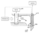
- FIG. 1 there is illustrated a schematic diagram of one embodiment of an apparatus 100 for isolating inactive fuel passages.
- an apparatus 100 for isolating inactive fuel passages there is illustrated a schematic diagram of one embodiment of an apparatus 100 for isolating inactive fuel passages.
- the reader should understand that the present application is not limited to the following embodiment unless specifically provided to the contrary.
- the apparatus 100 includes a fuel manifolding system with a gas manifold 102 and a liquid fuel manifold 104 .
- the gas manifold 102 is fed by a gas supply 106 , and may be fed gaseous fuel, air, purge air, and/or other gaseous streams at various operating conditions of the system 100 as understood by one of skill in the art. During some operating conditions, the gas manifold 102 may be shut off or flowing a nominal amount of gas.
- the gas supply 106 provides gaseous fuel and the gas manifold 102 feeds a plurality of gas injectors 108 for the operation of a turbine engine. The gas injectors 108 may feed into a combustion chamber 109 .
- the liquid fuel manifold 104 is fed by a liquid fuel supply 110 and a water flush supply 112 .
- the liquid fuel manifold 104 may be fed water or liquid fuel at various operating conditions of the apparatus 100 .
- the liquid fuel manifold 104 may be fed air, purge air, other streams, and/or may be shut off during some operating conditions.
- the liquid fuel supply 110 provides diesel fuel, kerosene, liquid natural gas, or similar fuels to liquid injectors 113 that feed an internal combustion engine such as a turbine engine.
- the liquid injectors 113 may feed into a combustion chamber 109 .
- the liquid fuel manifold 104 may be fed by lines including one-way valves 114 or similar protections to prevent flowback of fluids to the liquid supplies 110 , 112 .
- the apparatus 100 further includes a drain 116 fluidly connected to the gas manifold 102 and the liquid fuel manifold 104 .
- the drain 116 may comprise multiple drains 116 that may be separate from each other.
- the drain 116 may be separated from the manifolds 102 , 104 by one or more valves 118 .
- the valves 118 may comprise one-way valves, and may be controllable by an electronic controller (not shown) or the like.
- a valve 118 fluidly connected to the dormant manifold 102 , 104 is momentarily opened.
- the dormant manifold 102 , 104 may be pressurized by a purge fluid, causing the dormant manifold 102 , 104 to back-flush into the drain 116 .
- the purge fluid may be compressor air or any other generally inert fluid.
- FIGS. 2 and 3 there is illustrated a schematic diagram of one embodiment of a duct 202 in fluid communication with a combustion chamber 109 .
- the combustion chamber 109 forms a portion of a gas turbine engine.
- the present application is not limited to gas turbine engines.
- the duct 202 is a radial and/or annular duct 202 adapted to deliver a fuel and air mixture to the combustion chamber 109 .
- a gaseous fuel delivery device 204 discharges gaseous fuel into the duct 202 .
- the gaseous fuel delivery device 204 may be a fuel injector 108 such as one depicted in FIG. 1 .
- a liquid fuel passage 206 is adapted for passage of liquid fuel and/or a purging agent through at least one opening 208 formed in the duct wall 210 for the discharge of liquid fuel and/or a purging agent into the duct 202 .
- the opening 208 may be a discrete hole or a continuous opening.
- the at least one opening 208 is defined by a plurality of spaced openings (not shown).
- the at least one opening 208 is located downstream of the area of gas fuel injection 212 associated with the gaseous fuel delivery device 204 .
- the opening 216 may be a discrete hole or a continuous opening.
- the gas opening 216 may be a plurality of openings that correspond to the liquid fuel openings 208 .
- directly upstream indicates a geometric positioning (i.e.
- the distance that comprises directly upstream depends upon the flow rates in the duct 202 and the flow rate of gas coming out of the gas opening 216 .
- a substantial amount of the gas from the opening 216 should flow across the liquid fuel opening 208 before separation from the duct wall 210 and diffusion into the main duct 202 stream. The determinations for such an arrangement are mechanical steps for one of skill in the art based upon the disclosures herein.
- the fluid flow passage 214 is relatively small in comparison to the duct 202 and can deliver a flow of gas immediately upstream of the liquid fuel opening 208 .
- the flow of gas forms a shielding film directed in substantially the same direction as the bulk fluid flow in the duct 202 .
- the gas may be air that is extracted from a compressor associated with a turbine engine, however the present application is not limited to air from the compressor and the gas may be from other sources.
- the fluid flowable through the passage 214 is a gas and may or may not be air.
- the fluid flow passage 214 is concentric with the duct 202 .
- liquid fuel passes through the liquid fuel passage 206 and is supplied through the liquid fuel opening 208 into the duct 202 .
- the discharge of liquid fuel through the opening 208 may form a series of jets that discharge into the duct 202 .
- the fuel jets discharge at a high angle of attack into the flow of air or gaseous fuel and air mixture and are atomized by the shearing action of that flow of fluid in the duct 202 .
- the angle may be perpendicular as shown in FIG. 2 , although other angles are possible and it is a mechanical step for one of skill in the art to determine an angle sufficient for fuel atomization in a particular embodiment.
- the present application contemplates other directions of discharge in addition to perpendicular.
- the flow of gas through the fluid flow passage 214 has relatively little momentum in comparison to the liquid fuel jets through the liquid fuel opening 208 and does not influence the atomization of the liquid fuel jets.
- relatively little momentum indicates that if gas flow through the fluid flow passage 214 continues uninterrupted, the gas flow from the gas opening 216 does not significantly disturb the liquid fuel delivery through the liquid fuel opening 208 .
- FIG. 2 generally depicts a gaseous flow passage 214 upstream of a liquid fuel flow passage 206 , thereby creating a gas injector blocking and/or shielding an inactive liquid flow passage 206 .
- the upstream flow passage 214 may be a gas or liquid injection passage
- the downstream flow passage 206 may be a gas or liquid injection passage. Therefore, embodiments including an upstream injector shielding a downstream injector are contemplated within the scope of the present application.
- a wall portion 210 of the duct 202 between the gas opening 216 and the liquid fuel opening 208 is smooth and free of transitions that might cause the gas film to separate before reaching the liquid opening 208 .
- the gas delivered from the gas flow passage 214 may be delivered at a flow rate such that the gas remains in laminar flow across the liquid fuel opening 208 .
- Other wall configurations for the wall portion 210 are contemplated herein.
- a valve upon termination of liquid fuel flow, which may be just a temporary interruption of the liquid fuel flow, a valve acts to admit fluid to the liquid fuel passage 206 , flushing the passage 206 of liquid fuel.
- the fluid admitted to flush the liquid fuel passage 206 may be referred to herein as a purge fluid.
- the purge fluid may be water from an engine compressor wash water supply, nitrogen from air bottles, air, or other fluids believed to be known to one skilled in the art.
- the purge fluid comprises water from the water flush supply 112 .
- the flow of purge fluid is interrupted. It should be understood that in one embodiment there are periods of time when neither liquid fuel or purge fluid are passed through the liquid fuel passage 206 .
- the purge fluid flow may be controlled through valves and/or other flow control devices.
- the purge fluid flow may occur for a predetermined time calculated according to engine operating conditions during or preceding the purge, including but not limited to operating temperatures, properties of the fuel and/or purge fluid to be utilized, and other parameters known in the art that may affect the time and/or fluid volume required for an effective purge of the liquid fuel passage 206 and/or associated manifolds 102 , 104 , fuel supply lines, and the like.
- gaseous fuel is supplied to the gaseous fuel delivery device 204 with air in the duct 202 before discharging into the combustion chamber 109 .
- the film or curtain of air provided by the fluid flow passage 214 flows across the liquid fuel opening 208 and reduces or prevents the gas/air mixture in the duct 202 from entering the liquid fuel passage 206 .
- the gas film flowing over the opening(s) 208 function to aerodynamically isolate the inactive liquid fuel passage 206 from other fluid flow within the duct 202 .
- the gas provided by the fluid flow passage 214 partially or completely blocks the ingress of the gaseous fuel and air mixture flowing in the duct 202 into the entrance of the inactive liquid fuel passage 206 .
- the fluid flow passage 214 provides sufficient gas to ensure an air/fuel ratio within the inactive liquid fuel passage 206 less than that required to support combustion.
- the amount of gas that must be provided through the fluid flow passage 214 to achieve sufficient blockage depends upon the flow rates, fluid densities, and passage 206 , 214 and duct 202 sizes.
- the gas film is preferably formed of a quantity of clean air, however other gases and quality of air are contemplated herein.
- the fluid flow within the duct 202 proximate to the liquid fuel opening 208 is in a first direction, and the liquid fuel delivered through the opening 208 flows in a second direction substantially perpendicular to the first direction.
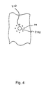
- the gaseous fluid passage 214 comprises a plurality of passages 214 fluidly connected to a plurality of gas flow openings 216 arranged concentrically around the liquid fuel opening 208 , and the gas delivered from the passages 214 flows substantially in the second direction (i.e. the direction of flow through the liquid fuel opening 208 ). At least one of the gas flow openings 216 arranged concentrically around the liquid fuel opening 208 is upstream of the liquid fuel opening 208 .
- the arrangement illustrated in the embodiment of FIG. 4 is similar to an air spoke atomizer, but the air flow in the gaseous fluid passages 214 is substantially lower than in a typical air spoke atomizer. Specifically, the gas flow through the passages 214 can continue during delivery of fuel through the liquid fuel opening 208 without disturbing the atomization and delivery of liquid fuel to the stream flowing in the duct 202 .
- a timeline 500 schematically illustrating isolating inactive fuel passages is depicted.
- the timeline indicates a flow value of purge air fluid 502 , a flow value of gaseous fuel 504 , a flow value of liquid fuel 506 , and a flow value of a liquid purge fluid 508 .
- the flows indicated in the timeline 500 are schematic only, and do not indicate relative flow rates or other features of the flows.
- the timeline 500 begins with an engine startup at time A and an engine shutdown at time G, but the operations of isolating inactive fuel passages may proceed on a continuing basis.
- the order of steps described herein is not intended to be limiting, and the steps may be performed in a different order, with delays, and the like unless explicitly stated otherwise.
- the timeline 500 begins with starting an engine and beginning a flow of purge air through the gaseous flow passage 214 at time A.
- the ramp-up time to achieve full gaseous flow is schematic only, and the actual time to full gaseous flow is dependent upon various parameters for a particular system. Other ramp-up and ramp-down times shown in the timeline 500 are similarly schematic in nature.
- the timeline 500 continues with beginning a gaseous fuel flow at time B. While the engine is fueled by gaseous fuel, the purge air flows and isolates the inactive liquid fuel passage 206 .
- An engine with dual-fuel capability begins a switch to liquid fuel at time C, which may include beginning with a water flush. After a prescribed time, occurring in the example at time D, the liquid fueling begins and the gaseous fueling is shut down.
- the engine begins to switch from liquid fueling to gaseous fueling.
- a water flush is performed for a period after the engine begins gaseous fueling.
- the purge air flows and isolates the inactive liquid fuel passage 206 .
- the gaseous fueling is shut off, the engine is shut down, and the purge air is shut down.
- the purge air flows throughout the engine operation from time A to time G, during times of liquid fueling and during times with no liquid fueling.
- the illustrated embodiment allows the use of a completely passive purging system to isolate inactive fuel passages 206 , allowing the purging system to operate without valves and controls.
- a variety of embodiments according to the present invention are contemplated.
- the fuel injector is utilized to deliver liquid fuel at times and includes a technique for flushing residual liquid fuel from the inactive fuel passage(s).
- the present application further contemplates a system that minimizes or prevents the introduction of hot combustion products and/or fuel and air into the inactive fuel passage(s) and includes a technique for flushing residual liquid fuel from the inactive fuel passage(s).
- Certain exemplary embodiments include an apparatus comprising a combustion chamber and a duct in fluid flow communication with the combustion chamber.
- the duct may be an annular duct.
- at least one opening is adapted for delivering liquid fuel into the duct and at least one passage adapted for delivery (i.e. delivery passage) of a gas upstream of the at least one opening for minimizing the entrance of a fluid other than the gas into the fuel delivery opening.
- the fluid flow in the duct comprises a gaseous fuel and air mixture.
- the fluid flow within the duct proximate to the at least one opening is in a first direction, and the gas delivered from the at least one passage flows substantially in the first direction.
- Certain embodiments include a gas deliverer adapted to deliver a gaseous fuel into the duct upstream of the at least one opening.
- the at least one opening defines a plurality of spaced openings in the duct.
- the at least one delivery passage is just prior to the at least one opening, and a wall portion of the duct between the at least one passage and the at least one opening is smooth.
- the gas delivered from the at least one passage may be delivered at a flow rate such that the gas remains in laminar flow across the at least one opening.
- a third fluid is in flow communication with the at least one opening adapted for delivering liquid fuel into the duct, the third fluid being selectively dispensed through the at least one opening.
- the third fluid may be a purge fluid.
- Certain exemplary embodiments include an apparatus comprising a combustion chamber and a duct in fluid flow communication with the combustion chamber. Further embodiments include a first passage adapted for delivering at least one of a liquid fuel and a purging fluid into the duct through at least one opening, and a gaseous fuel dispenser located upstream of the at least one opening; operable to dispense a gaseous fuel into the duct to form a gaseous fuel and air mixture. Further exemplary embodiments include a second passage adapted for delivering a gas through at least one hole located upstream of the at least one opening for shielding the at least one opening from the introduction of the gaseous fuel and air mixture from the duct.
- the second passage comprising a plurality of holes arranged concentrically around the first passage.
- the fluid flow within the duct may be in a first direction, where the first passage delivers the liquid fuel and/or purging fluid into the duct in a second direction.
- the second passage delivers the gas in substantially the second direction, and the second direction is substantially perpendicular to the first direction.
- Certain exemplary embodiments include a method comprising flowing a gaseous fuel and air mixture through a duct, and shielding an entrance to a liquid fuel delivery opening with a secondary gas to block the passage of the gaseous fuel and air mixture into the entrance.
- Certain exemplary embodiments include a method comprising discharging a gaseous fuel into a duct to form a fuel and air mixture, the duct being disposed in fluid flow communication with a combustion chamber.
- the method includes delivering a liquid fuel through a passage and out of at least one opening into the duct.
- the method further includes interrupting the delivering and flowing a second gas over the at least one opening to block the flow of the fuel and air mixture into the opening.
- the method further includes flowing the second gas in laminar flow over the at least one opening.
- the method may further include purging the passage of liquid fuel after interrupting the delivering, wherein purging the passage may comprise receiving purge air from a purge air supply, and flowing the purge air into a liquid fuel manifold in fluid communication with the passage.
- Certain exemplary embodiments include an apparatus comprising a combustion chamber and a duct in fluid flow communication with the combustion chamber.
- the apparatus further includes at least one liquid fuel delivery opening adapted for delivering a liquid fuel into the duct, and a means for aerodynamically isolating the at least one liquid fuel delivery opening from the duct.
- the method further includes a means for purging the liquid fuel from the at least one liquid fuel delivery opening.
Landscapes
- Engineering & Computer Science (AREA)
- Chemical & Material Sciences (AREA)
- Combustion & Propulsion (AREA)
- Mechanical Engineering (AREA)
- General Engineering & Computer Science (AREA)
- Nozzles (AREA)
- Feeding And Controlling Fuel (AREA)
- Output Control And Ontrol Of Special Type Engine (AREA)
Abstract
Description
- The present application claims the benefit of U.S. Provisional Patent Application No. 60/854,517 filed Oct. 26, 2006 which is incorporated herein by reference.
- The technical field generally relates to fuel injection, and more particularly relates to fuel injection where some fuel passages are inactive in some modes of operation. While the present application was developed for gas turbine engines, it is also applicable to other areas of technology including, but not limited to furnaces and rockets.
- Inactive fuel passage(s) may be found in equipment for many reasons including, but not limited to: a pilot injector which is utilized for low power operation and may be turned off as required at higher power; staged fuel injector(s) which may be turned on and off based upon desired operating parameters; and/or fuel injectors utilized for operation on different types of fuel at different times. During times that a fuel passage is inoperative, hot combustion products and/or fuel can enter the passages. Also, an inoperative fuel passage for liquid fuel may have stagnant residual fuel that may be altered from exposure to temperature and/or contaminants. Altered stagnant fuel may solidify or otherwise affect the performance of the fuel passage and fuel injector. There is a continued need for a system that minimizes or prevents the introduction of hot combustion products and/or fuel and air into the inactive fuel passage(s) and includes a technique for flushing residual liquid fuel from the inactive fuel passage(s) as disclosed herein.
- One embodiment relates to an apparatus having a combustion chamber and a duct in fluid flow communication with the combustion chamber. The apparatus includes at least one opening adapted for delivering a liquid fuel into the duct. The apparatus further includes at least one passage adapted for delivery of a gas upstream of the at least one opening for minimizing the entrance of a fluid other than the gas into the fuel delivery opening. Further embodiments, forms, objects, features, advantages, aspects, and benefits shall become apparent from the following descriptions, drawings, and claims.
-
FIG. 1 is a schematic diagram of one embodiment of an apparatus for isolating inactive fuel passages. -
FIG. 2 is a schematic diagram of one embodiment of a duct in fluid communication with a combustion chamber. -
FIG. 3 is a schematic diagram of one embodiment of at least one passage adapted for delivery of a gas upstream of an opening adapted for delivery of a liquid fuel into a duct. -
FIG. 4 is a schematic diagram of one embodiment of a plurality of passages arranged concentrically around the at least one opening adapted for delivery of a liquid fuel into a duct. -
FIG. 5 is a timeline schematically illustrating isolating inactive fuel passages. - For the purposes of promoting an understanding of the principles of the invention, reference will now be made to the embodiments illustrated in the drawings and specific language will be used to describe the same. It will nevertheless be understood that no limitation of the scope of the invention is thereby intended, such alterations and further modifications in the illustrated embodiments, and that such further applications of the principles of the invention as illustrated therein as would normally occur to one skilled in the art to which the invention relates are contemplated and protected.
- With reference to
FIG. 1 , there is illustrated a schematic diagram of one embodiment of anapparatus 100 for isolating inactive fuel passages. The reader should understand that the present application is not limited to the following embodiment unless specifically provided to the contrary. - The
apparatus 100 includes a fuel manifolding system with agas manifold 102 and aliquid fuel manifold 104. Thegas manifold 102 is fed by agas supply 106, and may be fed gaseous fuel, air, purge air, and/or other gaseous streams at various operating conditions of thesystem 100 as understood by one of skill in the art. During some operating conditions, thegas manifold 102 may be shut off or flowing a nominal amount of gas. In one embodiment, thegas supply 106 provides gaseous fuel and thegas manifold 102 feeds a plurality ofgas injectors 108 for the operation of a turbine engine. Thegas injectors 108 may feed into acombustion chamber 109. - The
liquid fuel manifold 104 is fed by aliquid fuel supply 110 and awater flush supply 112. Theliquid fuel manifold 104 may be fed water or liquid fuel at various operating conditions of theapparatus 100. In some embodiments, theliquid fuel manifold 104 may be fed air, purge air, other streams, and/or may be shut off during some operating conditions. In one embodiment, theliquid fuel supply 110 provides diesel fuel, kerosene, liquid natural gas, or similar fuels toliquid injectors 113 that feed an internal combustion engine such as a turbine engine. Theliquid injectors 113 may feed into acombustion chamber 109. Theliquid fuel manifold 104 may be fed by lines including one-way valves 114 or similar protections to prevent flowback of fluids to theliquid supplies - The
apparatus 100 further includes adrain 116 fluidly connected to thegas manifold 102 and theliquid fuel manifold 104. Thedrain 116 may comprisemultiple drains 116 that may be separate from each other. Thedrain 116 may be separated from themanifolds more valves 118. Thevalves 118 may comprise one-way valves, and may be controllable by an electronic controller (not shown) or the like. - In one embodiment, when fuel is not flowing to the
gas manifold 102 or theliquid fuel manifold 104, avalve 118 fluidly connected to thedormant manifold dormant manifold dormant manifold drain 116. The purge fluid may be compressor air or any other generally inert fluid. - Referring to
FIGS. 2 and 3 , there is illustrated a schematic diagram of one embodiment of aduct 202 in fluid communication with acombustion chamber 109. In one aspect, thecombustion chamber 109 forms a portion of a gas turbine engine. However, the present application is not limited to gas turbine engines. In one embodiment, theduct 202 is a radial and/orannular duct 202 adapted to deliver a fuel and air mixture to thecombustion chamber 109. A gaseousfuel delivery device 204 discharges gaseous fuel into theduct 202. In one aspect of the present application, the gaseousfuel delivery device 204 may be afuel injector 108 such as one depicted inFIG. 1 . - A
liquid fuel passage 206 is adapted for passage of liquid fuel and/or a purging agent through at least one opening 208 formed in theduct wall 210 for the discharge of liquid fuel and/or a purging agent into theduct 202. The opening 208 may be a discrete hole or a continuous opening. In another form the at least oneopening 208 is defined by a plurality of spaced openings (not shown). The at least one opening 208 is located downstream of the area ofgas fuel injection 212 associated with the gaseousfuel delivery device 204. - Another
fluid flow passage 214 adapted for passage of a gas through at least one opening 216 that may be upstream of theliquid fuel opening 208. The opening 216 may be a discrete hole or a continuous opening. The gas opening 216 may be a plurality of openings that correspond to theliquid fuel openings 208. For example, there may be one gas opening 216 upstream of each liquid fuel opening 208. In an alternate embodiment, there may be a plurality ofgas openings 216 for each liquid fuel opening 208, wherein at least one of the plurality ofgas openings 216 is directly upstream of the liquid fuel opening 208. As used herein, directly upstream indicates a geometric positioning (i.e. a position such that gas flowing from the gas opening 216 flows across the liquid fuel opening 208) and a distance positioning. The distance that comprises directly upstream depends upon the flow rates in theduct 202 and the flow rate of gas coming out of thegas opening 216. A substantial amount of the gas from theopening 216 should flow across the liquid fuel opening 208 before separation from theduct wall 210 and diffusion into themain duct 202 stream. The determinations for such an arrangement are mechanical steps for one of skill in the art based upon the disclosures herein. - In one form the
fluid flow passage 214 is relatively small in comparison to theduct 202 and can deliver a flow of gas immediately upstream of theliquid fuel opening 208. In one form of the present application the flow of gas forms a shielding film directed in substantially the same direction as the bulk fluid flow in theduct 202. The gas may be air that is extracted from a compressor associated with a turbine engine, however the present application is not limited to air from the compressor and the gas may be from other sources. For clarification, the fluid flowable through thepassage 214 is a gas and may or may not be air. In one form of the present application thefluid flow passage 214 is concentric with theduct 202. - In a liquid fuel operating mode, liquid fuel passes through the
liquid fuel passage 206 and is supplied through theliquid fuel opening 208 into theduct 202. The discharge of liquid fuel through theopening 208 may form a series of jets that discharge into theduct 202. In one form the fuel jets discharge at a high angle of attack into the flow of air or gaseous fuel and air mixture and are atomized by the shearing action of that flow of fluid in theduct 202. For example, the angle may be perpendicular as shown inFIG. 2 , although other angles are possible and it is a mechanical step for one of skill in the art to determine an angle sufficient for fuel atomization in a particular embodiment. The present application contemplates other directions of discharge in addition to perpendicular. - In one form of the present application, the flow of gas through the
fluid flow passage 214 has relatively little momentum in comparison to the liquid fuel jets through theliquid fuel opening 208 and does not influence the atomization of the liquid fuel jets. For the purposes of the present application, relatively little momentum indicates that if gas flow through thefluid flow passage 214 continues uninterrupted, the gas flow from thegas opening 216 does not significantly disturb the liquid fuel delivery through theliquid fuel opening 208. - For purposes of illustration,
FIG. 2 generally depicts agaseous flow passage 214 upstream of a liquidfuel flow passage 206, thereby creating a gas injector blocking and/or shielding an inactiveliquid flow passage 206. However, theupstream flow passage 214 may be a gas or liquid injection passage, and thedownstream flow passage 206 may be a gas or liquid injection passage. Therefore, embodiments including an upstream injector shielding a downstream injector are contemplated within the scope of the present application. - Referring to
FIG. 3 , in one preferred form of the present application awall portion 210 of theduct 202 between thegas opening 216 and theliquid fuel opening 208 is smooth and free of transitions that might cause the gas film to separate before reaching theliquid opening 208. The gas delivered from thegas flow passage 214 may be delivered at a flow rate such that the gas remains in laminar flow across theliquid fuel opening 208. Other wall configurations for thewall portion 210 are contemplated herein. - Referring back to
FIG. 2 , upon termination of liquid fuel flow, which may be just a temporary interruption of the liquid fuel flow, a valve acts to admit fluid to theliquid fuel passage 206, flushing thepassage 206 of liquid fuel. The fluid admitted to flush theliquid fuel passage 206 may be referred to herein as a purge fluid. The purge fluid may be water from an engine compressor wash water supply, nitrogen from air bottles, air, or other fluids believed to be known to one skilled in the art. In one embodiment, the purge fluid comprises water from the waterflush supply 112. - After a predetermined period of time, the flow of purge fluid is interrupted. It should be understood that in one embodiment there are periods of time when neither liquid fuel or purge fluid are passed through the
liquid fuel passage 206. The purge fluid flow may be controlled through valves and/or other flow control devices. The purge fluid flow may occur for a predetermined time calculated according to engine operating conditions during or preceding the purge, including but not limited to operating temperatures, properties of the fuel and/or purge fluid to be utilized, and other parameters known in the art that may affect the time and/or fluid volume required for an effective purge of theliquid fuel passage 206 and/or associatedmanifolds - In a pre-mix gas fuel mode, gaseous fuel is supplied to the gaseous
fuel delivery device 204 with air in theduct 202 before discharging into thecombustion chamber 109. The film or curtain of air provided by thefluid flow passage 214 flows across theliquid fuel opening 208 and reduces or prevents the gas/air mixture in theduct 202 from entering theliquid fuel passage 206. In one form the gas film flowing over the opening(s) 208 function to aerodynamically isolate the inactiveliquid fuel passage 206 from other fluid flow within theduct 202. In one embodiment, the gas provided by thefluid flow passage 214 partially or completely blocks the ingress of the gaseous fuel and air mixture flowing in theduct 202 into the entrance of the inactiveliquid fuel passage 206. In an embodiment where the ingress of the mixture is partially blocked, thefluid flow passage 214 provides sufficient gas to ensure an air/fuel ratio within the inactiveliquid fuel passage 206 less than that required to support combustion. The amount of gas that must be provided through thefluid flow passage 214 to achieve sufficient blockage depends upon the flow rates, fluid densities, andpassage duct 202 sizes. The gas film is preferably formed of a quantity of clean air, however other gases and quality of air are contemplated herein. - Referring to
FIG. 4 , in one embodiment the fluid flow within theduct 202 proximate to theliquid fuel opening 208 is in a first direction, and the liquid fuel delivered through theopening 208 flows in a second direction substantially perpendicular to the first direction. However, other flow directions are contemplated herein. Thegaseous fluid passage 214 comprises a plurality ofpassages 214 fluidly connected to a plurality ofgas flow openings 216 arranged concentrically around theliquid fuel opening 208, and the gas delivered from thepassages 214 flows substantially in the second direction (i.e. the direction of flow through the liquid fuel opening 208). At least one of thegas flow openings 216 arranged concentrically around theliquid fuel opening 208 is upstream of theliquid fuel opening 208. The arrangement illustrated in the embodiment ofFIG. 4 is similar to an air spoke atomizer, but the air flow in the gaseousfluid passages 214 is substantially lower than in a typical air spoke atomizer. Specifically, the gas flow through thepassages 214 can continue during delivery of fuel through theliquid fuel opening 208 without disturbing the atomization and delivery of liquid fuel to the stream flowing in theduct 202. - Referring to
FIG. 5 , atimeline 500 schematically illustrating isolating inactive fuel passages is depicted. The timeline indicates a flow value ofpurge air fluid 502, a flow value ofgaseous fuel 504, a flow value ofliquid fuel 506, and a flow value of aliquid purge fluid 508. The flows indicated in thetimeline 500 are schematic only, and do not indicate relative flow rates or other features of the flows. - For purposes of illustration, the
timeline 500 begins with an engine startup at time A and an engine shutdown at time G, but the operations of isolating inactive fuel passages may proceed on a continuing basis. The order of steps described herein is not intended to be limiting, and the steps may be performed in a different order, with delays, and the like unless explicitly stated otherwise. - The
timeline 500 begins with starting an engine and beginning a flow of purge air through thegaseous flow passage 214 at time A. The ramp-up time to achieve full gaseous flow is schematic only, and the actual time to full gaseous flow is dependent upon various parameters for a particular system. Other ramp-up and ramp-down times shown in thetimeline 500 are similarly schematic in nature. Thetimeline 500 continues with beginning a gaseous fuel flow at time B. While the engine is fueled by gaseous fuel, the purge air flows and isolates the inactiveliquid fuel passage 206. An engine with dual-fuel capability begins a switch to liquid fuel at time C, which may include beginning with a water flush. After a prescribed time, occurring in the example at time D, the liquid fueling begins and the gaseous fueling is shut down. - At a later time E, the engine begins to switch from liquid fueling to gaseous fueling. In one embodiment, a water flush is performed for a period after the engine begins gaseous fueling. Again during gaseous fueling the purge air flows and isolates the inactive
liquid fuel passage 206. At a time G, the gaseous fueling is shut off, the engine is shut down, and the purge air is shut down. In one embodiment, the purge air flows throughout the engine operation from time A to time G, during times of liquid fueling and during times with no liquid fueling. The illustrated embodiment allows the use of a completely passive purging system to isolateinactive fuel passages 206, allowing the purging system to operate without valves and controls. - As is evident from the figures and text presented above, a variety of embodiments according to the present invention are contemplated. In one form of the present application there is provided a system for minimizing or preventing the introduction of hot combustion products and/or fuel and air into the inactive fuel passage(s). In another form of the present application the fuel injector is utilized to deliver liquid fuel at times and includes a technique for flushing residual liquid fuel from the inactive fuel passage(s). The present application further contemplates a system that minimizes or prevents the introduction of hot combustion products and/or fuel and air into the inactive fuel passage(s) and includes a technique for flushing residual liquid fuel from the inactive fuel passage(s).
- Certain exemplary embodiments include an apparatus comprising a combustion chamber and a duct in fluid flow communication with the combustion chamber. The duct may be an annular duct. In further exemplary embodiments at least one opening is adapted for delivering liquid fuel into the duct and at least one passage adapted for delivery (i.e. delivery passage) of a gas upstream of the at least one opening for minimizing the entrance of a fluid other than the gas into the fuel delivery opening. In further exemplary embodiments, the fluid flow in the duct comprises a gaseous fuel and air mixture. In some embodiments, the fluid flow within the duct proximate to the at least one opening is in a first direction, and the gas delivered from the at least one passage flows substantially in the first direction.
- Certain embodiments include a gas deliverer adapted to deliver a gaseous fuel into the duct upstream of the at least one opening. In some embodiments, the at least one opening defines a plurality of spaced openings in the duct. In certain exemplary embodiments, the at least one delivery passage is just prior to the at least one opening, and a wall portion of the duct between the at least one passage and the at least one opening is smooth. The gas delivered from the at least one passage may be delivered at a flow rate such that the gas remains in laminar flow across the at least one opening.
- In further exemplary embodiments, a third fluid is in flow communication with the at least one opening adapted for delivering liquid fuel into the duct, the third fluid being selectively dispensed through the at least one opening. The third fluid may be a purge fluid.
- Certain exemplary embodiments include an apparatus comprising a combustion chamber and a duct in fluid flow communication with the combustion chamber. Further embodiments include a first passage adapted for delivering at least one of a liquid fuel and a purging fluid into the duct through at least one opening, and a gaseous fuel dispenser located upstream of the at least one opening; operable to dispense a gaseous fuel into the duct to form a gaseous fuel and air mixture. Further exemplary embodiments include a second passage adapted for delivering a gas through at least one hole located upstream of the at least one opening for shielding the at least one opening from the introduction of the gaseous fuel and air mixture from the duct. Further embodiments include the second passage comprising a plurality of holes arranged concentrically around the first passage. In a further embodiment, the fluid flow within the duct may be in a first direction, where the first passage delivers the liquid fuel and/or purging fluid into the duct in a second direction. In an exemplary embodiment, the second passage delivers the gas in substantially the second direction, and the second direction is substantially perpendicular to the first direction.
- Certain exemplary embodiments include a method comprising flowing a gaseous fuel and air mixture through a duct, and shielding an entrance to a liquid fuel delivery opening with a secondary gas to block the passage of the gaseous fuel and air mixture into the entrance.
- Certain exemplary embodiments include a method comprising discharging a gaseous fuel into a duct to form a fuel and air mixture, the duct being disposed in fluid flow communication with a combustion chamber. In further embodiments, the method includes delivering a liquid fuel through a passage and out of at least one opening into the duct. The method further includes interrupting the delivering and flowing a second gas over the at least one opening to block the flow of the fuel and air mixture into the opening. In certain embodiments, the method further includes flowing the second gas in laminar flow over the at least one opening. The method may further include purging the passage of liquid fuel after interrupting the delivering, wherein purging the passage may comprise receiving purge air from a purge air supply, and flowing the purge air into a liquid fuel manifold in fluid communication with the passage.
- Certain exemplary embodiments include an apparatus comprising a combustion chamber and a duct in fluid flow communication with the combustion chamber. The apparatus further includes at least one liquid fuel delivery opening adapted for delivering a liquid fuel into the duct, and a means for aerodynamically isolating the at least one liquid fuel delivery opening from the duct. In certain embodiments, the method further includes a means for purging the liquid fuel from the at least one liquid fuel delivery opening.
- While the invention has been illustrated and described in detail in the drawings and foregoing description, the same is to be considered as illustrative and not restrictive in character, it being understood that only the preferred embodiments have been shown and described and that all changes and modifications that come within the spirit of the inventions are desired to be protected. It should be understood that while the use of words such as preferable, preferably, preferred, more preferred or exemplary utilized in the description above indicate that the feature so described may be more desirable or characteristic, nonetheless may not be necessary and embodiments lacking the same may be contemplated as within the scope of the invention, the scope being defined by the claims that follow. In reading the claims, it is intended that when words such as “a,” “an,” “at least one,” or “at least one portion” are used there is no intention to limit the claim to only one item unless specifically stated to the contrary in the claim. When the language “at least a portion” and/or “a portion” is used the item can include a portion and/or the entire item unless specifically stated to the contrary. A portion of the disclosure of this patent document contains material which is subject to copyright protection. The copyright owner has no objection to the facsimile reproduction by anyone of the patent document or the patent disclosure, as it appears in the Patent and Trademark Office patent files or records, but otherwise reserves all copyright rights whatsoever.
Claims (25)
Priority Applications (1)
| Application Number | Priority Date | Filing Date | Title |
|---|---|---|---|
| US11/978,241 US7934380B2 (en) | 2006-10-26 | 2007-10-26 | Method and apparatus for isolating inactive fuel passages |
Applications Claiming Priority (2)
| Application Number | Priority Date | Filing Date | Title |
|---|---|---|---|
| US85451706P | 2006-10-26 | 2006-10-26 | |
| US11/978,241 US7934380B2 (en) | 2006-10-26 | 2007-10-26 | Method and apparatus for isolating inactive fuel passages |
Publications (2)
| Publication Number | Publication Date |
|---|---|
| US20080098994A1 true US20080098994A1 (en) | 2008-05-01 |
| US7934380B2 US7934380B2 (en) | 2011-05-03 |
Family
ID=39864418
Family Applications (1)
| Application Number | Title | Priority Date | Filing Date |
|---|---|---|---|
| US11/978,241 Active 2028-03-22 US7934380B2 (en) | 2006-10-26 | 2007-10-26 | Method and apparatus for isolating inactive fuel passages |
Country Status (4)
| Country | Link |
|---|---|
| US (1) | US7934380B2 (en) |
| EP (1) | EP2079963B1 (en) |
| CA (1) | CA2667430C (en) |
| WO (1) | WO2008125907A2 (en) |
Cited By (11)
| Publication number | Priority date | Publication date | Assignee | Title |
|---|---|---|---|---|
| FR2938048A1 (en) * | 2008-11-06 | 2010-05-07 | Ge Energy Products France Snc | SYSTEM AND METHOD FOR WASHING AND PURGING THE LIQUID COMBUSTIBLE CIRCUIT OF A TURBINE |
| US20110023816A1 (en) * | 2006-03-23 | 2011-02-03 | Lonox Engine Company, Inc. | Internal combustion water injection engine |
| US20110100015A1 (en) * | 2009-11-05 | 2011-05-05 | General Electric Company | Gas turbine system to inhibit coke formation and methods of use |
| CH704446A1 (en) * | 2011-02-02 | 2012-08-15 | Alstom Technology Ltd | Heat transfer assembly. |
| US20130199576A1 (en) * | 2012-02-06 | 2013-08-08 | General Electric Company | System and method to clear a liquid fuel supply line |
| US20150140204A1 (en) * | 2012-07-11 | 2015-05-21 | Toyota Shatai Kabushiki Kaisha | Fuel cell separator and method for manufacturing same |
| US20170138268A1 (en) * | 2014-06-03 | 2017-05-18 | Mitsubishi Hitachi Power Systems, Ltd. | Method for purging fuel channel, purging device for executing said method, and gas turbine installation provided with said device |
| US10794296B2 (en) * | 2016-10-24 | 2020-10-06 | Mitsubishi Hitachi Power Systems, Ltd. | Gas turbine combustor and method of operating the same |
| US20220325668A1 (en) * | 2021-04-12 | 2022-10-13 | Pratt & Whitney Canada Corp. | Fuel systems and methods for purging |
| US20240392729A1 (en) * | 2020-05-14 | 2024-11-28 | Bj Energy Solutions, Llc | Systems and methods utilizing turbine compressor discharge for hydrostatic manifold purge |
| US20250198620A1 (en) * | 2023-12-18 | 2025-06-19 | Ge Infrastructure Technology Llc | Fuel injection assembly having partial direct injectors |
Families Citing this family (3)
| Publication number | Priority date | Publication date | Assignee | Title |
|---|---|---|---|---|
| WO2008125907A2 (en) | 2006-10-26 | 2008-10-23 | Rolls-Royce Power Engineering Plc | Method and apparatus for isolating inactive fuel passages |
| EP2379944B1 (en) * | 2008-12-19 | 2019-08-07 | Ansaldo Energia S.p.A. | Method for supplying a gas turbine plant and gas turbine plant |
| GB2487934B (en) * | 2011-02-08 | 2015-07-08 | Bosch Gmbh Robert | Fuel injection apparatus comprising a fuel atomisation system |
Citations (11)
| Publication number | Priority date | Publication date | Assignee | Title |
|---|---|---|---|---|
| US2617252A (en) * | 1947-11-07 | 1952-11-11 | Douglas Aircraft Co Inc | Rotary turbocompressor jet engine after-burner |
| US2697910A (en) * | 1950-07-29 | 1954-12-28 | Thermal Res And Engineering Co | Fluid fuel burner with self-contained fuel vaporizing unit |
| US3777983A (en) * | 1971-12-16 | 1973-12-11 | Gen Electric | Gas cooled dual fuel air atomized fuel nozzle |
| US4168609A (en) * | 1977-12-01 | 1979-09-25 | United Technologies Corporation | Folded-over pilot burner |
| US5680766A (en) * | 1996-01-02 | 1997-10-28 | General Electric Company | Dual fuel mixer for gas turbine combustor |
| US5778676A (en) * | 1996-01-02 | 1998-07-14 | General Electric Company | Dual fuel mixer for gas turbine combustor |
| US6250065B1 (en) * | 1998-04-21 | 2001-06-26 | Mitsubishi Heavy Industries, Ltd. | Gas turbine combustion system and combustor ignition method therefor |
| US20030121269A1 (en) * | 2001-12-28 | 2003-07-03 | Mick Warren James | Liquid fuel nozzle apparatus with passive protective purge |
| US20060168966A1 (en) * | 2005-02-01 | 2006-08-03 | Power Systems Mfg., Llc | Self-Purging Pilot Fuel Injection System |
| US20070028617A1 (en) * | 2005-07-25 | 2007-02-08 | General Electric Company | Air-assisted fuel injector for mixer assembly of a gas turbine engine combustor |
| US20070231762A1 (en) * | 2004-06-07 | 2007-10-04 | Stefano Bernero | Injector for Liquid Fuel, and Staged Premix Burner Having This Injector |
Family Cites Families (10)
| Publication number | Priority date | Publication date | Assignee | Title |
|---|---|---|---|---|
| US4041695A (en) | 1975-11-21 | 1977-08-16 | The Garrett Corporation | Fuel system pneumatic purge apparatus and method |
| US4327547A (en) | 1978-11-23 | 1982-05-04 | Rolls-Royce Limited | Fuel injectors |
| US5277023A (en) | 1991-10-07 | 1994-01-11 | Fuel Systems Textron, Inc. | Self-sustaining fuel purging fuel injection system |
| US5243816A (en) | 1992-06-19 | 1993-09-14 | Fuel Systems Textron, Inc. | Self purging fuel injector |
| GB9321505D0 (en) | 1993-10-19 | 1993-12-08 | Europ Gas Turbines Ltd | Fuel injector |
| US6675583B2 (en) | 2000-10-04 | 2004-01-13 | Capstone Turbine Corporation | Combustion method |
| US6735949B1 (en) * | 2002-06-11 | 2004-05-18 | General Electric Company | Gas turbine engine combustor can with trapped vortex cavity |
| US7013649B2 (en) * | 2004-05-25 | 2006-03-21 | General Electric Company | Gas turbine engine combustor mixer |
| US7603863B2 (en) | 2006-06-05 | 2009-10-20 | General Electric Company | Secondary fuel injection from stage one nozzle |
| WO2008125907A2 (en) | 2006-10-26 | 2008-10-23 | Rolls-Royce Power Engineering Plc | Method and apparatus for isolating inactive fuel passages |
-
2007
- 2007-10-26 WO PCT/IB2007/004564 patent/WO2008125907A2/en not_active Ceased
- 2007-10-26 US US11/978,241 patent/US7934380B2/en active Active
- 2007-10-26 EP EP07873351.6A patent/EP2079963B1/en active Active
- 2007-10-26 CA CA2667430A patent/CA2667430C/en active Active
Patent Citations (12)
| Publication number | Priority date | Publication date | Assignee | Title |
|---|---|---|---|---|
| US2617252A (en) * | 1947-11-07 | 1952-11-11 | Douglas Aircraft Co Inc | Rotary turbocompressor jet engine after-burner |
| US2697910A (en) * | 1950-07-29 | 1954-12-28 | Thermal Res And Engineering Co | Fluid fuel burner with self-contained fuel vaporizing unit |
| US3777983A (en) * | 1971-12-16 | 1973-12-11 | Gen Electric | Gas cooled dual fuel air atomized fuel nozzle |
| US4168609A (en) * | 1977-12-01 | 1979-09-25 | United Technologies Corporation | Folded-over pilot burner |
| US5680766A (en) * | 1996-01-02 | 1997-10-28 | General Electric Company | Dual fuel mixer for gas turbine combustor |
| US5778676A (en) * | 1996-01-02 | 1998-07-14 | General Electric Company | Dual fuel mixer for gas turbine combustor |
| US6250065B1 (en) * | 1998-04-21 | 2001-06-26 | Mitsubishi Heavy Industries, Ltd. | Gas turbine combustion system and combustor ignition method therefor |
| US20030121269A1 (en) * | 2001-12-28 | 2003-07-03 | Mick Warren James | Liquid fuel nozzle apparatus with passive protective purge |
| US6609380B2 (en) * | 2001-12-28 | 2003-08-26 | General Electric Company | Liquid fuel nozzle apparatus with passive protective purge |
| US20070231762A1 (en) * | 2004-06-07 | 2007-10-04 | Stefano Bernero | Injector for Liquid Fuel, and Staged Premix Burner Having This Injector |
| US20060168966A1 (en) * | 2005-02-01 | 2006-08-03 | Power Systems Mfg., Llc | Self-Purging Pilot Fuel Injection System |
| US20070028617A1 (en) * | 2005-07-25 | 2007-02-08 | General Electric Company | Air-assisted fuel injector for mixer assembly of a gas turbine engine combustor |
Cited By (19)
| Publication number | Priority date | Publication date | Assignee | Title |
|---|---|---|---|---|
| US20110023816A1 (en) * | 2006-03-23 | 2011-02-03 | Lonox Engine Company, Inc. | Internal combustion water injection engine |
| US7938103B2 (en) * | 2006-03-23 | 2011-05-10 | Lonox Engine Company, Inc. | Internal combustion water injection engine |
| US9410486B2 (en) | 2008-11-06 | 2016-08-09 | Ge Energy Products France Snc | System and method for washing and purging the liquid fuel system of a turbine with water |
| WO2010052434A3 (en) * | 2008-11-06 | 2010-11-11 | Ge Energy Products France Snc | System and method for washing and purging the liquid fuel system of a turbine with water |
| FR2938048A1 (en) * | 2008-11-06 | 2010-05-07 | Ge Energy Products France Snc | SYSTEM AND METHOD FOR WASHING AND PURGING THE LIQUID COMBUSTIBLE CIRCUIT OF A TURBINE |
| US20110100015A1 (en) * | 2009-11-05 | 2011-05-05 | General Electric Company | Gas turbine system to inhibit coke formation and methods of use |
| CN102052154A (en) * | 2009-11-05 | 2011-05-11 | 通用电气公司 | Gas turbine system to inhibit coke formation and methods of use |
| CH704446A1 (en) * | 2011-02-02 | 2012-08-15 | Alstom Technology Ltd | Heat transfer assembly. |
| US20130199576A1 (en) * | 2012-02-06 | 2013-08-08 | General Electric Company | System and method to clear a liquid fuel supply line |
| US20150140204A1 (en) * | 2012-07-11 | 2015-05-21 | Toyota Shatai Kabushiki Kaisha | Fuel cell separator and method for manufacturing same |
| US9515324B2 (en) * | 2012-07-11 | 2016-12-06 | Toyota Shatai Kabushiki Kaisha | Method for manufacturing fuel cell separator |
| US20170138268A1 (en) * | 2014-06-03 | 2017-05-18 | Mitsubishi Hitachi Power Systems, Ltd. | Method for purging fuel channel, purging device for executing said method, and gas turbine installation provided with said device |
| US10378448B2 (en) * | 2014-06-03 | 2019-08-13 | Mitsubishi Hitachi Power Systems, Ltd. | Method for purging fuel channel, purging device for executing said method, and gas turbine installation provided with said device |
| US10794296B2 (en) * | 2016-10-24 | 2020-10-06 | Mitsubishi Hitachi Power Systems, Ltd. | Gas turbine combustor and method of operating the same |
| US20240392729A1 (en) * | 2020-05-14 | 2024-11-28 | Bj Energy Solutions, Llc | Systems and methods utilizing turbine compressor discharge for hydrostatic manifold purge |
| US20220325668A1 (en) * | 2021-04-12 | 2022-10-13 | Pratt & Whitney Canada Corp. | Fuel systems and methods for purging |
| US11808219B2 (en) * | 2021-04-12 | 2023-11-07 | Pratt & Whitney Canada Corp. | Fuel systems and methods for purging |
| US12435675B2 (en) | 2021-04-12 | 2025-10-07 | Pratt & Whitney Canada Corp. | Fuel systems and methods for purging |
| US20250198620A1 (en) * | 2023-12-18 | 2025-06-19 | Ge Infrastructure Technology Llc | Fuel injection assembly having partial direct injectors |
Also Published As
| Publication number | Publication date |
|---|---|
| WO2008125907A3 (en) | 2009-05-28 |
| CA2667430A1 (en) | 2008-10-23 |
| WO2008125907A2 (en) | 2008-10-23 |
| CA2667430C (en) | 2014-12-16 |
| EP2079963A2 (en) | 2009-07-22 |
| US7934380B2 (en) | 2011-05-03 |
| EP2079963B1 (en) | 2018-09-19 |
Similar Documents
| Publication | Publication Date | Title |
|---|---|---|
| US7934380B2 (en) | Method and apparatus for isolating inactive fuel passages | |
| US7921651B2 (en) | Operation of dual gas turbine fuel system | |
| EP2213863B1 (en) | System and method for water injection in a turbine engine | |
| US20090272097A1 (en) | Independent Manifold Dual Gas Turbine Fuel System | |
| US6256975B1 (en) | Method for reliably removing liquid fuel from the fuel system of a gas turbine, and a device for carrying out the method | |
| US7185485B2 (en) | Method and system for failure accommodation of gas generator fuel metering system | |
| US6073436A (en) | Fuel injector with purge passage | |
| US20030121269A1 (en) | Liquid fuel nozzle apparatus with passive protective purge | |
| JPS6112096B2 (en) | ||
| EP2831500B1 (en) | Rapid gas exchange and delivery system | |
| US8438830B2 (en) | Primary manifold dual gas turbine fuel system | |
| US20090272096A1 (en) | Single Manifold Dual Gas Turbine Fuel System | |
| EP3017157B1 (en) | Arrangement for and method of feeding ammonia containing fluid into the exhaust gas passage of a combustion plant | |
| JP4206908B2 (en) | Gas turbine combustor | |
| KR101465442B1 (en) | Supply Apparatus of Gas Fuel Having Converging-Diverging Nozzle | |
| US5009589A (en) | Stored energy combustor fuel injection system | |
| US9926847B2 (en) | Method and apparatus for isolating inactive fuel passages | |
| US20250215833A1 (en) | Firing apparatus and firing method for high reactive fuel gases | |
| JP7735159B2 (en) | Method for stopping operation of a heat quantity adjustment device | |
| JP3066777B2 (en) | Fuel control device for gas turbine combustor | |
| CA3142100C (en) | Gas turbine water injection for emissions reduction | |
| JPH05125958A (en) | Liquid fuel supply device |
Legal Events
| Date | Code | Title | Description |
|---|---|---|---|
| AS | Assignment |
Owner name: ROLLS-ROYCE POWER ENGINEERING PLC, ENGLAND Free format text: ASSIGNMENT OF ASSIGNORS INTEREST;ASSIGNORS:INNES, MATTHEW CHRISTOPHER;OMIELAN, WALTER KASIMIERZ;HAMBY, RICHARD JOHN;REEL/FRAME:020366/0199 Effective date: 20071219 |
|
| STCF | Information on status: patent grant |
Free format text: PATENTED CASE |
|
| FPAY | Fee payment |
Year of fee payment: 4 |
|
| FEPP | Fee payment procedure |
Free format text: PAYOR NUMBER ASSIGNED (ORIGINAL EVENT CODE: ASPN); ENTITY STATUS OF PATENT OWNER: LARGE ENTITY |
|
| AS | Assignment |
Owner name: INDUSTRIAL TURBINE COMPANY (UK) LIMITED, UNITED KI Free format text: ASSIGNMENT OF ASSIGNORS INTEREST;ASSIGNOR:ROLLS-ROYCE POWER ENGINEERING PLC;REEL/FRAME:035035/0491 Effective date: 20140803 |
|
| MAFP | Maintenance fee payment |
Free format text: PAYMENT OF MAINTENANCE FEE, 8TH YEAR, LARGE ENTITY (ORIGINAL EVENT CODE: M1552); ENTITY STATUS OF PATENT OWNER: LARGE ENTITY Year of fee payment: 8 |
|
| MAFP | Maintenance fee payment |
Free format text: PAYMENT OF MAINTENANCE FEE, 12TH YEAR, LARGE ENTITY (ORIGINAL EVENT CODE: M1553); ENTITY STATUS OF PATENT OWNER: LARGE ENTITY Year of fee payment: 12 |