EP2213863B1 - System and method for water injection in a turbine engine - Google Patents
System and method for water injection in a turbine engine Download PDFInfo
- Publication number
- EP2213863B1 EP2213863B1 EP10151312.5A EP10151312A EP2213863B1 EP 2213863 B1 EP2213863 B1 EP 2213863B1 EP 10151312 A EP10151312 A EP 10151312A EP 2213863 B1 EP2213863 B1 EP 2213863B1
- Authority
- EP
- European Patent Office
- Prior art keywords
- water
- water injection
- injection system
- valve
- pressure
- Prior art date
- Legal status (The legal status is an assumption and is not a legal conclusion. Google has not performed a legal analysis and makes no representation as to the accuracy of the status listed.)
- Not-in-force
Links
Images


Classifications
-
- F—MECHANICAL ENGINEERING; LIGHTING; HEATING; WEAPONS; BLASTING
- F02—COMBUSTION ENGINES; HOT-GAS OR COMBUSTION-PRODUCT ENGINE PLANTS
- F02C—GAS-TURBINE PLANTS; AIR INTAKES FOR JET-PROPULSION PLANTS; CONTROLLING FUEL SUPPLY IN AIR-BREATHING JET-PROPULSION PLANTS
- F02C3/00—Gas-turbine plants characterised by the use of combustion products as the working fluid
- F02C3/20—Gas-turbine plants characterised by the use of combustion products as the working fluid using a special fuel, oxidant, or dilution fluid to generate the combustion products
- F02C3/30—Adding water, steam or other fluids for influencing combustion, e.g. to obtain cleaner exhaust gases
- F02C3/305—Increasing the power, speed, torque or efficiency of a gas turbine or the thrust of a turbojet engine by injecting or adding water, steam or other fluids
-
- F—MECHANICAL ENGINEERING; LIGHTING; HEATING; WEAPONS; BLASTING
- F23—COMBUSTION APPARATUS; COMBUSTION PROCESSES
- F23L—SUPPLYING AIR OR NON-COMBUSTIBLE LIQUIDS OR GASES TO COMBUSTION APPARATUS IN GENERAL ; VALVES OR DAMPERS SPECIALLY ADAPTED FOR CONTROLLING AIR SUPPLY OR DRAUGHT IN COMBUSTION APPARATUS; INDUCING DRAUGHT IN COMBUSTION APPARATUS; TOPS FOR CHIMNEYS OR VENTILATING SHAFTS; TERMINALS FOR FLUES
- F23L7/00—Supplying non-combustible liquids or gases, other than air, to the fire, e.g. oxygen, steam
- F23L7/002—Supplying water
-
- F—MECHANICAL ENGINEERING; LIGHTING; HEATING; WEAPONS; BLASTING
- F23—COMBUSTION APPARATUS; COMBUSTION PROCESSES
- F23R—GENERATING COMBUSTION PRODUCTS OF HIGH PRESSURE OR HIGH VELOCITY, e.g. GAS-TURBINE COMBUSTION CHAMBERS
- F23R3/00—Continuous combustion chambers using liquid or gaseous fuel
- F23R3/28—Continuous combustion chambers using liquid or gaseous fuel characterised by the fuel supply
- F23R3/286—Continuous combustion chambers using liquid or gaseous fuel characterised by the fuel supply having fuel-air premixing devices
-
- F—MECHANICAL ENGINEERING; LIGHTING; HEATING; WEAPONS; BLASTING
- F05—INDEXING SCHEMES RELATING TO ENGINES OR PUMPS IN VARIOUS SUBCLASSES OF CLASSES F01-F04
- F05D—INDEXING SCHEME FOR ASPECTS RELATING TO NON-POSITIVE-DISPLACEMENT MACHINES OR ENGINES, GAS-TURBINES OR JET-PROPULSION PLANTS
- F05D2260/00—Function
- F05D2260/20—Heat transfer, e.g. cooling
- F05D2260/212—Heat transfer, e.g. cooling by water injection
-
- F—MECHANICAL ENGINEERING; LIGHTING; HEATING; WEAPONS; BLASTING
- F05—INDEXING SCHEMES RELATING TO ENGINES OR PUMPS IN VARIOUS SUBCLASSES OF CLASSES F01-F04
- F05D—INDEXING SCHEME FOR ASPECTS RELATING TO NON-POSITIVE-DISPLACEMENT MACHINES OR ENGINES, GAS-TURBINES OR JET-PROPULSION PLANTS
- F05D2260/00—Function
- F05D2260/60—Fluid transfer
- F05D2260/602—Drainage
-
- F—MECHANICAL ENGINEERING; LIGHTING; HEATING; WEAPONS; BLASTING
- F05—INDEXING SCHEMES RELATING TO ENGINES OR PUMPS IN VARIOUS SUBCLASSES OF CLASSES F01-F04
- F05D—INDEXING SCHEME FOR ASPECTS RELATING TO NON-POSITIVE-DISPLACEMENT MACHINES OR ENGINES, GAS-TURBINES OR JET-PROPULSION PLANTS
- F05D2260/00—Function
- F05D2260/85—Starting
-
- F—MECHANICAL ENGINEERING; LIGHTING; HEATING; WEAPONS; BLASTING
- F05—INDEXING SCHEMES RELATING TO ENGINES OR PUMPS IN VARIOUS SUBCLASSES OF CLASSES F01-F04
- F05D—INDEXING SCHEME FOR ASPECTS RELATING TO NON-POSITIVE-DISPLACEMENT MACHINES OR ENGINES, GAS-TURBINES OR JET-PROPULSION PLANTS
- F05D2270/00—Control
- F05D2270/01—Purpose of the control system
- F05D2270/08—Purpose of the control system to produce clean exhaust gases
- F05D2270/082—Purpose of the control system to produce clean exhaust gases with as little NOx as possible
-
- F—MECHANICAL ENGINEERING; LIGHTING; HEATING; WEAPONS; BLASTING
- F05—INDEXING SCHEMES RELATING TO ENGINES OR PUMPS IN VARIOUS SUBCLASSES OF CLASSES F01-F04
- F05D—INDEXING SCHEME FOR ASPECTS RELATING TO NON-POSITIVE-DISPLACEMENT MACHINES OR ENGINES, GAS-TURBINES OR JET-PROPULSION PLANTS
- F05D2270/00—Control
- F05D2270/01—Purpose of the control system
- F05D2270/16—Purpose of the control system to control water or steam injection
-
- F—MECHANICAL ENGINEERING; LIGHTING; HEATING; WEAPONS; BLASTING
- F23—COMBUSTION APPARATUS; COMBUSTION PROCESSES
- F23N—REGULATING OR CONTROLLING COMBUSTION
- F23N2237/00—Controlling
- F23N2237/22—Controlling water injection
-
- F—MECHANICAL ENGINEERING; LIGHTING; HEATING; WEAPONS; BLASTING
- F23—COMBUSTION APPARATUS; COMBUSTION PROCESSES
- F23N—REGULATING OR CONTROLLING COMBUSTION
- F23N2241/00—Applications
- F23N2241/20—Gas turbines
-
- Y—GENERAL TAGGING OF NEW TECHNOLOGICAL DEVELOPMENTS; GENERAL TAGGING OF CROSS-SECTIONAL TECHNOLOGIES SPANNING OVER SEVERAL SECTIONS OF THE IPC; TECHNICAL SUBJECTS COVERED BY FORMER USPC CROSS-REFERENCE ART COLLECTIONS [XRACs] AND DIGESTS
- Y02—TECHNOLOGIES OR APPLICATIONS FOR MITIGATION OR ADAPTATION AGAINST CLIMATE CHANGE
- Y02T—CLIMATE CHANGE MITIGATION TECHNOLOGIES RELATED TO TRANSPORTATION
- Y02T50/00—Aeronautics or air transport
- Y02T50/60—Efficient propulsion technologies, e.g. for aircraft
-
- Y—GENERAL TAGGING OF NEW TECHNOLOGICAL DEVELOPMENTS; GENERAL TAGGING OF CROSS-SECTIONAL TECHNOLOGIES SPANNING OVER SEVERAL SECTIONS OF THE IPC; TECHNICAL SUBJECTS COVERED BY FORMER USPC CROSS-REFERENCE ART COLLECTIONS [XRACs] AND DIGESTS
- Y10—TECHNICAL SUBJECTS COVERED BY FORMER USPC
- Y10T—TECHNICAL SUBJECTS COVERED BY FORMER US CLASSIFICATION
- Y10T137/00—Fluid handling
- Y10T137/7722—Line condition change responsive valves
- Y10T137/7837—Direct response valves [i.e., check valve type]
- Y10T137/7838—Plural
Definitions
- the subject matter disclosed herein relates to a turbine engine and, more specifically, to a system and method for water injection.
- a turbine engine may include one or more combustors, which receive and combust compressed air and fuel to produce hot combustion gases. Under certain operating conditions (e.g., liquid fuel operation), water may be injected into the combustors to reduce emissions of oxides of nitrogen (NOx) and/or carbon monoxide (CO), among other exhaust emissions.
- NOx oxides of nitrogen
- CO carbon monoxide
- flow instabilities may occur in the water lines during start-up conditions. For example, pressure oscillations may occur between a water injection system and a pressure regulating valve upstream of the water injection system. More specifically, the pressure regulating valve may be unable to transition to a low flow rate during initiation of the water injection system. These flow instabilities may cause substantial delay in the setup and operation of the turbine engine with a liquid fuel.
- US 6145294 discloses a purge system for flushing liquid fuel and water from the combustion section of a gas turbine system as well as for providing continuous cooling of the nozzles.
- the gas turbine may operate on liquid fuel or gaseous fuel.
- the turbine is switched to burn gaseous fuel, the liquid fuel remaining in the liquid fuel system is flushed by a liquid fuel purge system.
- water in the water injection system is purged from nozzles in the combustion system by a water purge system.
- the purge system operates in conjunction with an air atomization system, but does not rely on an atomizing air compressor to boost the pressure of the purge air.
- the purge system utilizes pressurized air from the gas turbine compressor and directs the purge air to manifolds which distribute air to the atomizing air passages, liquid fuel nozzles, and water injection nozzles via purge valves and soft purge valves.
- a system comprising: a pressure regulating valve; a water injection system configured to supply water from the pressure regulating valve to a water manifold of a turbine engine via a water conduit; wherein the water injection system comprises a self-contained unit comprising: at least one water injection pump configured to transfer water from the pressure regulating valve to the water manifold of the turbine engine; a plurality of flow meters in fluid communication with the at least one water injection pump and located downstream from the at least one water injection pump; and a stop valve in fluid communication with the flow meters and located downstream from the flow meters; and a drain valve disposed on a drain line upstream of the at least one water injection pump; and a controller configured to control the drain valve to drain at least a portion of the water from the pressure regulating valve during a start-up period of the water injection system at least until a stable water pressure is achieved downstream of the pressure regulating valve.
- the invention also provides a method of supplying water from a pressure regulating valve to a water manifold of a turbine using the system above, the method comprising: controlling the drain valve on the drain line upstream of the at least one water injection pump to stabilize water pressure between the pressure regulating valve and the water injection system during a startup period; and activating the water injection system to deliver water to a water manifold of the turbine engine after stabilizing the water pressure via opening the drain valve.
- Embodiments of the present disclosure may reduce flow instabilities within a water injection system during a start-up period.
- Certain embodiments may include a drain valve coupled to a water line that connects a pressure regulating valve to the water injection system.
- the drain valve may be opened. With the drain valve open, water flows from the pressure regulating valve to both the water injection system and the drain.
- the water injection system may be activated after stable water flow is detected at an inlet to the water injection system.
- the drain valve may be closed after a desired flow rate through the water injection system is achieved. Finally, water flow rate may be ramped to a desired level based on fuel flow through the turbine system. In this manner, stable water flow through the water injection system at start-up may be achieved, facilitating proper water flow to the turbine engine.
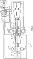
- FIG. 1 a block diagram of an embodiment of a gas turbine system 10 is illustrated.
- the diagram includes fuel nozzle 12, fuel supply 14, and combustor 16.
- fuel supply 14 routes a liquid fuel and/or gas fuel, such as natural gas, to the turbine system 10 through fuel nozzle 12 into combustor 16.
- the fuel nozzle 12 is configured to inject and mix the fuel with compressed air.
- the combustor 16 ignites and combusts the fuel-air mixture, and then passes hot pressurized exhaust gas into a turbine 18.
- the exhaust gas passes through turbine blades in the turbine 18, thereby driving the turbine 18 to rotate.
- the coupling between blades in turbine 18 and shaft 19 will cause the rotation of shaft 19, which is also coupled to several components throughout the turbine system 10, as illustrated.
- the exhaust of the combustion process may exit the turbine system 10 via exhaust outlet 20.
- compressor vanes or blades are included as components of compressor 22. Blades within compressor 22 may be coupled to shaft 19, and will rotate as shaft 19 is driven to rotate by turbine 18. Compressor 22 may intake air to turbine system 10 via air intake 24. Further, shaft 19 may be coupled to load 26, which may be powered via rotation of shaft 19. As appreciated, load 26 may be any suitable device that may generate power via the rotational output of turbine system 10, such as a power generation plant or an external mechanical load. For example, load 26 may include an electrical generator, a propeller of an airplane, and so forth. Air intake 24 draws air 30 into turbine system 10 via a suitable mechanism, such as a cold air intake, for subsequent mixture of air 30 with fuel supply 14 via fuel nozzle 12.
- a suitable mechanism such as a cold air intake
- air 30 taken in by turbine system 10 may be fed and compressed into pressurized air by rotating blades within compressor 22.
- the pressurized air may then be fed into fuel nozzle 12, as shown by arrow 32.
- Fuel nozzle 12 may then mix the pressurized air and fuel, shown by numeral 34, to produce a suitable mixture ratio for combustion, e.g., a combustion that causes the fuel to more completely burn, so as not to waste fuel or cause excess emissions.
- the system 10 may include water injection, via fuel nozzles 12, to reduce emissions associated with liquid fuel operation.
- a water injection system 36 may supply water to fuel nozzles 12.
- the water injection system 36 may be a stand alone unit, such as a skid-mounted unit, which is separate or independent from the turbine system 10.
- the water injection system 36 may be separate or independent from a water supply 38.
- the water injection system 36 may receive water from the water supply 38, and then act as an intermediary to route the water to the turbine system 10 (e.g., a water injection manifold).
- the water may flow through a pressure regulating valve 40 between the water supply 38 and the water injection system 36. Pressure regulating valve 40 automatically adjusts water flow to achieve a desired water pressure.
- the pressure regulating valve 40 may be configured to operate at high flow rates (not low flow rates) due to the high water demands by the water injection system 36 and turbine system 10. As a result, water pressure oscillations may develop at the pressure regulating valve 40 and/or between the valve 40 and the water injection system 36 during the low flow rates of water injection system start-up.
- turbine system 10 includes a drain valve 42 configured to open during water injection system initiation to establish stable flow.
- controller 44 determines that activation is appropriate for water injection system 36, then controller 44 directs drain valve 42 to open. Water then flows through drain valve 42 until water pressure has stabilized. Once controller 44 detects stable water flow, controller 44 activates water injection system 36. Controller 44 then closes drain valve 42 when a desired water flow rate is achieved. In this manner, stable water flow is established prior to activation of water injection system 36.
- FIG. 2 presents a detailed block diagram of the water injection system 36 shown in FIG. 1 .
- Water flows from water supply 38 through pressure regulating valve 40 and a water conduit 45 to water injection system 36.
- a drain line 46 is coupled to water conduit 45 downstream of pressure regulating valve 40 and upstream of water injection system 36.
- Water entering drain line 46 flows through drain valve 42, an orifice 48, a manual isolation valve 50 and ultimately exits to a drain.
- Drain valve 42 is configured to open to establish stable water flow prior to activation of water injection system 36.
- Orifice 48 is configured to restrict flow through drain line 46.
- the diameter of drain line 46 is greater than approximately 0.5, 1, 1.5, 2, 2.5, 3, or 3.5 inches, or any diameter therebetween.
- drain line 46 has about a 2 inch diameter
- the diameter of orifice 48 may be approximately 0.25 to 0.75 inches, 0.3 to 0.7 inches, 0.4 to 0.6 inches, or approximately 0.47 inches.
- orifice 48 may restrict water flow such that only about 20 to 90 gallons, 30 to 80 gallons, 40 to 70 gallons, or about 60 gallons of water flows through drain line 46 during water injection system start-up.
- the diameter of drain line 46 and orifice 48 may be varied based on water flow criteria. For example, larger diameters may be employed for turbine systems that utilize greater water flow rates.
- manual isolation valve 50 is disposed along drain line 46 downstream from orifice 48.
- Manual isolation valve 50 serves to isolate water injection system 36 from the drain when water injection system 36 is inoperative. For example, if the turbine system is operating on gaseous fuel, water injection system 36 may remain inactive for long periods. Therefore, manual isolation valve 50 may be closed to seal water injection system 36.
- a pressure sensor 52 may be disposed within water injection system 36 adjacent to an inlet 53. Pressure sensor 52 is communicatively coupled to controller 44 and configured to send a signal to controller 44 indicative of water pressure. For example, during start-up, pressure sensor 52 may measure water pressure fluctuations and send a signal to controller 44 indicative of these fluctuations. Controller 44 may then analyze this signal to determine whether the fluctuations are within established parameters for water injection system activation.
- Water injection system 36 is activated, in part, by engaging water pumps 54.
- each water pump 54 is driven by a motor 56 controlled by a variable frequency drive (VFD) 58.
- VFDs 58 facilitate continuous variation of pump motor speed.
- VFDs 58 may vary the frequency of electricity supplied to pump motors 56 such that pump motors 56 may be operated at different speeds. Varying the speed of pump motors 56 may change the amount of water that flows through pumps 54.
- VFDs 58 are commutatively coupled to controller 44 such that controller 44 may activate pumps 54 and vary their capacity. For example, when a low water flow rate is desired, controller 44 may instruct pumps 54 to operate at a low capacity via VFDs 58.
- controller 44 may instruct VFDs 58 to increase capacity of pumps 54.
- the embodiment presented in FIG. 2 includes two pumps 54 connected in parallel. However, other embodiments may employ either more or fewer pumps 54, arranged in parallel or serial flow configurations.
- a pressure sensor 60 is coupled to water injection system 36 downstream from pumps 54 and configured to measure the pressure of water exiting pumps 54.
- Pressure sensor 60 is communicatively coupled to controller 44 and configured to send a signal to controller 44 indicative of water pressure. Based on this signal, controller 44 may adjust pump operation to achieve a desired water pressure.
- Flow meters 62 are disposed downstream from pressure sensor 60 and configured to measure the water flow rate exiting pumps 54. Flow meters 62 are communicatively coupled to controller 44 and configured to send a signal indicative of flow rate such that controller 44 may adjust pump operation to achieve a desired flow rate.
- Target water flow rate is based on turbine system demand. For example, during periods of high turbine load, target water flow rate may increase.
- controller 44 may increase pump speed until flow meters 62 indicate that the target flow rate has been achieved.
- a stop valve 64 is disposed downstream from flow meters 62. Stop valve 64 may be closed when water injection system 36 is not operating and may open upon activation of water injection system 36. Stop valve 64 may block water from entering the turbine engine when water injection is not desired (e.g., during gas fuel operation). Stop valve 64 is communicatively coupled to controller 44 such that controller 44 may open stop valve 64 in response to water injection system 36 activation.
- Water from water injection system 36 flows to a water injection manifold 66 located downstream from water injection system 36.
- water injection manifold 66 includes a cylindrical member disposed around the turbine engine, wherein the manifold 66 is configured to deliver water to each combustor.
- Water injection manifold 66 may provide equal water flow to each combustor within the turbine system.
- a flow proportioning valve 68 Prior to entering the combustors, water flows through a flow proportioning valve 68 configured to distribute water flow to each fuel nozzle within a combustor. Water may then enter the combustor and combine with fuel and air to reduce turbine system emissions.
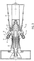
- FIG. 3 shows a cutaway side view of an embodiment of turbine system 10 that may be used in conjunction with the water injection system 36 with flow stabilization features of the disclosed embodiments.
- the disclosed embodiments stabilize the water flow upstream of the water injection system 36 to enable easy setup and operation of the turbine system 10 with liquid fuel and water injection.
- the embodiment includes compressor 22, which is coupled to an annular array of combustors 16.
- eighteen combustors 16 may be located in turbine system 10.
- Each combustor 16 includes one or more fuel nozzles 12, which feed an air-fuel mixture to a combustion zone located within each combustor 16.
- each combustor 16 may include 1, 2, 3, 4, 5, 6, 7, 8, 9, 10, or more fuel nozzles 12 in an annular or other suitable arrangement. Combustion of the air-fuel mixture within combustors 16 will cause vanes or blades within turbine 18 to rotate as exhaust gas passes toward exhaust outlet 20.
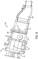
- FIG. 4 is a detailed cutaway side view illustration of an embodiment of combustor 16 that may be used with turbine system 10 in conjunction with the water injection system 36 with flow stabilization features of the disclosed embodiments. As discussed above, the disclosed embodiments stabilize the water flow upstream of the water injection system 36 to enable easy setup and operation of the turbine system 10 with liquid fuel and water injection in each combustor 16.
- combustor 16 includes fuel nozzles 12 that are attached to an end cover 70 at a base or head end 71 of combustor 16.
- a typical arrangement of combustor 16 may include five or six fuel nozzles 12.
- Other embodiments of combustor 16 may use a single large fuel nozzle 12.
- the surfaces and geometry of fuel nozzles 12 are designed to provide an optimal mixture and flow path for air and fuel as it flows downstream into combustor 16, thereby enabling increased combustion in the chamber, thus producing more power in the turbine engine.
- the fuel mixture is expelled from fuel nozzles 12 downstream in direction 72 to a combustion zone 74 inside combustor casing 76.
- Combustion zone 74 is the location where ignition of the air-fuel mixture is most appropriate within combustor 16.
- combustion zone 74 is located inside combustor casing 76, downstream from fuel nozzles 12 and upstream from a transition piece 78, which directs the pressurized exhaust gas toward turbine 18.
- Transition piece 78 includes a converging section that enables a velocity increase as the combusted exhaust flows out of combustor 16, producing a greater force to turn turbine 18. In turn, the exhaust gas causes rotation of shaft 19 to drive load 26.
- combustor 16 also includes liner 80 located inside casing 76 to provide a hollow annular path for a cooling air flow, which cools the casing 76 around combustion zone 74. Liner 80 also may provide a suitable contour to improve flow from fuel nozzles 12 to turbine 18.
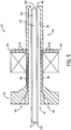
- FIG. 5 is a cutaway side view of an exemplary fuel nozzle 12 that may be used in combustor 16 in conjunction with the water injection system 36 with flow stabilization features of the disclosed embodiments.
- fuel nozzle 12 is configured to supply air, water, liquid fuel and gaseous fuel to combustor 16.
- Fuel nozzle 12 includes a rearward supply section 82 and a forward delivery section 84.
- Reward supply section 82 includes inlets configured to receive fluid from the combustor head end 71.
- Forward delivery section 84 is configured to deliver the fluids to the combustion zone of the combustor 16.
- Gaseous fuel enters gas inlets 86 and flows through gas passages 88 to gaseous fuel injectors 90.
- Gaseous fuel injectors 90 include apertures 92 configured to transfer gaseous fuel from injectors 90 to the combustor 16.
- air enters annular air inlet 94, flows through air passage 96 and exits orifice 98. In this manner, air flows from the combustor head end 71 toward the combustion zone 74.
- Water enters annular water inlet 100 and flows through water passage 102.
- Liquid fuel enters liquid fuel inlet 104 and flows through liquid fuel passage 106. Both water and liquid fuel exit fuel nozzle 12 through orifice 108.
- the addition of water to the fuel-air mixture reduces NOx and CO emissions.
- FIG. 6 presents a flowchart of a method 110 of establishing stable water flow prior to activation of the water injection system 36.
- water injection system activation criteria are verified to determine whether the water injection system 36 may be activated. As discussed in detail below, the water injection system 36 may be activated in response to certain turbine system 10 operating conditions. If these conditions are satisfied, the drain valve 42 is opened, as represented by block 114. Opening the drain valve 42 allows water from the pressure regulating valve 40 to flow into the drain.
- water pressure at the inlet 53 to the water injection system 36 is measured to determine whether stable water pressure has been established.
- Water pressure stabilizes when pressure remains within a specified tolerance of a desired pressure for a particular time period.
- desired water pressure for water injection system activation is approximately 65 psi.
- a tolerance of +/- 5 psi and a minimum time of 5 seconds may be established.
- method 110 may continue to the next step.
- desired pressure may be approximately 30 to 120 psi, 40 to 100 psi, 50 to 80 psi, or approximately 65 psi.
- tolerance may be less than about 1, 2, 3, 4, 5, 6, 7 or 8 psi, or any pressure therebetween.
- minimum time may be greater than approximately 1, 2, 3, 4, 5, 6, 7 or 8 seconds, or any time therebetween.
- method 110 may repeat step 116 until water pressure has stabilized.
- method 110 may employ a timeout period after which an operator is informed that stable water flow has not been established. For example, a timeout period of approximately 30 seconds may be instituted. In such a configuration, if stable water flow has not been established within approximately 30 seconds after entering step 116, an operator is informed of the situation so corrective action may be taken (e.g., closing the pressure regulating valve 40). Shorter or longer timeout periods may be employed in alternative embodiments. For example, the timeout period may be greater than about 10, 20, 30, 40, 50, or 60 seconds, or any time therebetween.
- the water injection system 36 may be activated, as represented by block 118. As discussed in detail below, activation of the water injection system 36 may involve a series of steps, including turning on the pumps 54 and opening the stop valve 64. Once the water injection system 36 has been activated, method 110 proceeds to step 120 and determines whether a desired water flow rate has been established.
- the desired water injection flow rate is between about 30 to 150 gallons per minute (gpm), 60 to 120 gpm, 80 to 100 gpm, or about 90 gpm.
- This flow rate may correspond to a multiple of drain flow capacity.
- drain flow capacity may be between about 10 to 50 gpm, 20 to 40 gpm, 25 to 35 gpm, or about 30 gpm.
- desired water flow rate at the water injection system inlet 53 may be greater than approximately 2, 2.5, 3, 3.5, or 4 times the drain flow rate, or any multiple therebetween. For example, if drain flow capacity is approximately 30 gpm and the multiple is approximately 3, desired flow rate at the water injection system inlet 53 may be approximately 90 gpm. Other embodiments may employ a different multiple and/or different drain and/or water injection inlet flow rates.
- another timeout may be employed such that an operator is informed if desired flow is not established within a certain time period after water injection system activation. In certain embodiments, this timeout period may be approximately 1 to 10 minutes, 3 to 7 minutes, 4 to 6 minutes, or approximately 5 minutes. For example, if desired water flow rate is not established after about 5 minutes, an operator is informed so that corrective action may be taken (e.g., deactivation of the water injection system 36). The timeout period may be longer or shorter in alternative embodiments.
- the drain valve 42 is closed, as represented by block 122.
- the drain valve 42 may be configured to close over a period of time. For example, certain embodiments may close the drain valve over a period of approximately 5 to 60 seconds, 10 to 50 seconds, 20 to 40 seconds, or approximately 25 seconds.
- the water injection flow rate may be ramped up to a target level, as represented by block 124.
- the target level corresponds to the water flow criteria of the turbine system 10. For example, during high load conditions, the turbine system 10 may utilize increased water flow rates to ensure the turbine system 10 is operating within regulatory emission levels.
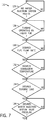
- FIG. 7 shows a detailed flowchart of the steps preformed in block 112 of FIG. 6 in one embodiment.
- Block 112 determines whether the water injection system activation criteria have been met.
- the first criteria is an absence of water injection system faults.
- the controller 44 may poll each component (e.g., pumps 54, stop valve 64, etc.) within the water injection system 36 to determine whether it is operational. If a component is not operational, activation of the water injection system 36 may be undesirable because the system may operate inefficiently, if at all. However, if no water injection system faults are detected, method 112 may proceed to the next step.
- each component e.g., pumps 54, stop valve 64, etc.
- step 1208 determines whether the turbine system 10 is operating solely on liquid fuel. As previously discussed, the turbine system 10 may operate on liquid and/or gaseous fuel. During periods of gaseous fuel operation, regulatory emissions requirements may be satisfied without the use of water injection. Therefore, step 128 limits water injection system activation to liquid fuel operation in which water injection may reduce emissions to desired levels.
- fuel flow may be examined to determine whether a sufficient fuel flow rate for water injection has been established, as represented by block 130.
- water utilization may be reduced by suspending water injection in such regimes.
- water injection may serve to reduce turbine system emissions to acceptable levels.
- the water injection system 36 is activated in response to (or upon reaching) a target flow rate. If the turbine system fuel flow exceeds the target flow rate, combustor temperature may be monitored to determine whether it has reached a sufficient level for water injection system activation, as represented by block 132. Similar to step 130, operating the turbine system 10 within certain combustor temperature regimes may produce emissions within regulatory limits without the use of water injection. Therefore, the water injection system 36 may be activated when combustor temperature falls outside of this range.
- turbine load may be measured to determine whether the load is sufficient to activate the water injection system 36, as represented by block 134. For example, when the turbine system 10 is initiated, turbine speed may be gradually increased to a desired level before a load is applied. With regard to power generation, the turbine may be activated and set to a desired rotational rate prior to engaging the generator. Typically, emissions from the turbine system 10 do not exceed established levels while the turbine system 10 is unloaded. Therefore, the water injection system 36 may not be activated until a sufficient load is sensed.
- pressure at the water injection system inlet 53 is measured to determine whether pressure has reached a desired level.
- this pressure may be about 10 to 60 psi, 20 to 40 psi, 25 to 35 psi, or about 30 psi.
- Other embodiments may utilize a higher or lower water injection system initiation pressure. If the desired pressure has been established, step 112 is complete and the method of establishing stable flow prior to water injection system activation may continue. However, if the desired pressure is not established, an operator may be informed of the situation after a timeout period. In certain embodiments, this timeout period may be greater than approximately 10, 15, 20, 25, 30, 35, 40, or 45 seconds, or any time therebetween. For example, if approximately 30 seconds have elapsed since step 136 commenced and desired system inlet pressure has not been established, an operator may be informed and corrective action may be taken to resolve the situation.
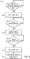
- FIG. 8 shows a detailed flowchart of the steps preformed in block 118 of FIG. 6 in one embodiment.
- Step 118 includes steps for activating the water injection system 36.
- a minimum target water injection flow rate is set, as represented by block 138. This minimum flow rate facilitates establishing stable flow through the water injection system 36 prior to ramping flow to a desired level.
- the water injection pumps 54 are activated, as represented by block 140.
- the controller 44 may activate the pumps 54 by instructing the VFDs 58 to engage the pump motors 56. Once the pumps 54 are engaged, water pressure increases throughout the water injection system 36.
- a time delay is implemented to facilitate this pressure increase prior to opening the stop valve 64, as represented by block 144.
- water may flow through the water manifold 66 to the fuel nozzles 12 of the turbine system 10, completing the flow path from the water supply 38.
- water injection flow rate is ramped up to a target level, as represented by block 146.
- the target level may be determined based on fuel flow rate. For example, higher water flow rates may be utilized during periods of increased fuel flow to ensure compliance with emissions standards. Once the desired water injection flow rate is achieved, the method of establishing stable water flow may continue.
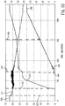
- FIG. 9 is a graph of water flow rates verses time during water injection system activation when stable flow has not been established. This figure represents a situation in which the controller 44 does not activate the drain valve 42 during water injection system start-up.
- Curve 148 represents the desired water flow rate
- curve 150 represents the actual water flow rate
- curve 152 represents water pressure at the inlet 53 to the water injection system 36
- curve 154 represents commanded water injection pump output. Desired water flow rate is determined by the turbine system 10. Based on certain parameters (e.g., combustor temperature, fuel flow rate, etc.), the turbine system 10 computes a desired water flow rate sufficient to reduce emissions to acceptable levels. As illustrated by curve 148, the turbine system 10 then sends an electronic signal indicative of this desired flow rate to the water injection system controller 44.
- certain parameters e.g., combustor temperature, fuel flow rate, etc.
- Curve 150 represents the actual water flow rate produced by the water injection system 36. During water injection system operation, it is desirable for the actual water flow rate to substantially coincide with the desired water flow rate. As can be seen from FIG. 9 , the actual water flow rate 150 is not tracking the desired water flow rate 148. As explained in detail below, this poor correlation is due to flow instabilities within the water injection system 36.
- inlet pressure drops sharply at approximately 20 seconds.
- This pressure drop 156 is due to flow instabilities within the water injection system 36.
- the water injection pumps 54 are activated at approximately the same time as the inlet pressure drop 156.
- the pressure regulating valve 40 is configured to automatically adjust flow to achieve a desired pressure.
- the water injection system 36 is configured to automatically vary pump capacity to achieve a desired flow rate.
- interaction between the pressure regulating valve 40 and the pumps 54 creates oscillations within the water injection system 36 because the pressure regulating valve 40 is not configured to transition from zero flow to low flow operation.
- the pressure regulating valve 40 is set to full open to compensate for the oscillations.
- a second water pressure drop 158 begins at approximately 45 seconds, in which interaction between the pressure regulating valve 40 and the pumps 54 causes water inlet pressure to drop sharply.
- the water injection system 36 terminates flow 160 and reinitializes.
- curve 152 illustrates, water pressure at the water injection system inlet 53 drops to approximately zero at flow termination 160. Therefore, the water injection system 36 shuts down because there is very little water flow into the pumps 54. The process then repeats until a second flow termination 162, where a third attempt is made to activate the water injection system 36. As seen from FIG. 9 , all three attempts are unsuccessful. In other words, actual water flow 150 never substantially coincides with desired water flow 148.
- FIG. 10 is a graph of water flow rates verses time during water injection system activation when stable flow is established.
- Curve 164 represents a desired water flow rate
- curve 166 represents an actual water flow rate
- curve 168 represents water pressure at the water injection system inlet 53
- curve 170 represents commanded pump capacity.
- actual water flow rate closely tracks desired water flow rate, indicating a successful water injection system start-up.
- the drain valve 40 is opened 172.
- stable water pressure is achieved 174, approximately five seconds after the drain valve 42 is opened 172.
- water pressure stabilizes when pressure remains within a specified tolerance of a desired pressure for a particular time period.
- desired water pressure for water injection system activation is approximately 65 psi.
- a tolerance of about +/- 5 psi and a minimum time of about 5 seconds is established. In other words, if water pressure remains between approximately 60 psi and 70 psi for approximately 5 seconds, water pressure is considered stable.
- water pressure remains between 60 psi and 70 psi for more than five seconds after the drain valve 42 is opened 172. Therefore, based on the parameters defined above, water pressure has stabilized 174.
- the water injection system 36 is initiated. As seen from curve 170, water pumps 54 are activated 176 approximately five seconds after stable pressure is established 174. As curve 168 illustrates, water pressure fluctuates after the pumps 54 are activated 176 due to interaction between the pumps 54 and the pressure regulating valve 40. However, these fluctuations are relatively small compared to the steep pressure drops seen in FIG. 9 . At approximately 70 seconds, the stop valve 64 is opened 178, allowing water to flow into the turbine engine. Furthermore, at this point, water flow rate begins to ramp to a target level.
- the drain valve 42 is closed 180 because water flow rate has reached a predetermined level. At this point, the water injection system 36 may operate normally without diverting water to the drain. Finally, at approximately 230 seconds, the water injection flow rate reaches the desired level 182. As seen from curves 164 and 166, actual water flow rate closely tracks desired water flow rate throughout the entire ramp-up and steady-state flow regimes. As FIG. 10 illustrates, opening and closing the drain valve 42 facilitates stable water flow through the water injection system 36 during system initiation.
- the disclosed embodiments address the pressure fluctuations associated with the pressure regulating valve 40 and the water injection system 36 both attempting to stabilize the water flow.
- the system may not be able to stabilize the water flow to the turbine engine.
- it may be particularly difficult to setup and use liquid fuel with the turbine engine, due to the problems associated with the water injection.
- the drain valve 42 enables flow stabilization first with the pressure regulating valve 40, followed by ramping up of the water injection system 36. That is, the drain valve 42 essentially changes a simultaneous or parallel control scheme (i.e., flow control by both valve 40 and system 36) to a series or sequential control scheme (i.e., valve 40 followed by system 36).
- the drain valve 42 reduces or eliminates the conflict between the pressure control features of the pressure regulating valve 40 and the water injection system 36.
- the drain valve 42 ensures that stable flow is provided to the water injection system 36, thereby reducing or eliminating the possibility that the water injection system 36 will fight with pressure regulating valve 40.
Description
- The subject matter disclosed herein relates to a turbine engine and, more specifically, to a system and method for water injection.
- A turbine engine may include one or more combustors, which receive and combust compressed air and fuel to produce hot combustion gases. Under certain operating conditions (e.g., liquid fuel operation), water may be injected into the combustors to reduce emissions of oxides of nitrogen (NOx) and/or carbon monoxide (CO), among other exhaust emissions. Unfortunately, flow instabilities may occur in the water lines during start-up conditions. For example, pressure oscillations may occur between a water injection system and a pressure regulating valve upstream of the water injection system. More specifically, the pressure regulating valve may be unable to transition to a low flow rate during initiation of the water injection system. These flow instabilities may cause substantial delay in the setup and operation of the turbine engine with a liquid fuel.
-
US 6145294 discloses a purge system for flushing liquid fuel and water from the combustion section of a gas turbine system as well as for providing continuous cooling of the nozzles. The gas turbine may operate on liquid fuel or gaseous fuel. When the turbine is switched to burn gaseous fuel, the liquid fuel remaining in the liquid fuel system is flushed by a liquid fuel purge system. Similarly, water in the water injection system is purged from nozzles in the combustion system by a water purge system. The purge system operates in conjunction with an air atomization system, but does not rely on an atomizing air compressor to boost the pressure of the purge air. Instead, the purge system utilizes pressurized air from the gas turbine compressor and directs the purge air to manifolds which distribute air to the atomizing air passages, liquid fuel nozzles, and water injection nozzles via purge valves and soft purge valves. - Certain embodiments commensurate in scope with the originally claimed invention are summarized below. These embodiments are not intended to limit the scope of the claimed invention, but rather these embodiments are intended only to provide a brief summary of possible forms of the invention. Indeed, the invention may encompass a variety of forms that may be similar to or different from the embodiments set forth below.
- According to the present invention there is provided a system, comprising: a pressure regulating valve; a water injection system configured to supply water from the pressure regulating valve to a water manifold of a turbine engine via a water conduit; wherein the water injection system comprises a self-contained unit comprising: at least one water injection pump configured to transfer water from the pressure regulating valve to the water manifold of the turbine engine; a plurality of flow meters in fluid communication with the at least one water injection pump and located downstream from the at least one water injection pump; and a stop valve in fluid communication with the flow meters and located downstream from the flow meters; and a drain valve disposed on a drain line upstream of the at least one water injection pump; and a controller configured to control the drain valve to drain at least a portion of the water from the pressure regulating valve during a start-up period of the water injection system at least until a stable water pressure is achieved downstream of the pressure regulating valve.
- The invention also provides a method of supplying water from a pressure regulating valve to a water manifold of a turbine using the system above, the method comprising: controlling the drain valve on the drain line upstream of the at least one water injection pump to stabilize water pressure between the pressure regulating valve and the water injection system during a startup period; and activating the water injection system to deliver water to a water manifold of the turbine engine after stabilizing the water pressure via opening the drain valve.
- There follows a detailed description of embodiments of the invention by way of example only with reference to the accompanying drawings, in which:
-
FIG. 1 is a block diagram of a turbine system having a water injection system configured to establish stable water flow prior to activation in accordance with certain embodiments of the present technique; -
FIG. 2 is a block diagram of the water injection system, as shown inFIG. 1 , in accordance with certain embodiments of the present technique; -
FIG. 3 is a cutaway side view of the turbine system, as shown inFIG. 1 , in accordance with certain embodiments of the present technique; -
FIG. 4 is a cutaway side view of a combustor, taken within line 4-4 as shown inFIG. 3 , in accordance with certain embodiments of the present technique; -
FIG. 5 is a cutaway side view of a fuel nozzle, as shown inFIG. 4 , in accordance with certain embodiments of the present technique; -
FIG. 6 is a flowchart of a method of establishing stable water flow into the water injection system prior to activation, in accordance with certain embodiments of the present technique; -
FIG. 7 is a flowchart of a method of determining whether water injection system activation criteria have been met, in accordance with certain embodiments of the present technique; -
FIG. 8 is a flowchart of a method of activating the water injection system, in accordance with certain embodiments of the present technique; -
FIG. 9 is a graph of water flow rates verses time during water injection system start-up when stable flow has not been established, in accordance with certain embodiments of the present technique; and -
FIG. 10 is a graph of water flow rates verses time during water injection system start-up when stable flow has been established, in accordance with certain embodiments of the present technique. - One or more specific embodiments of the present invention will be described below. In an effort to provide a concise description of these embodiments, all features of an actual implementation may not be described in the specification. It should be appreciated that in the development of any such actual implementation, as in any engineering or design project, numerous implementation-specific decisions must be made to achieve the developers' specific goals, such as compliance with system-related and business-related constraints, which may vary from one implementation to another. Moreover, it should be appreciated that such a development effort might be complex and time consuming, but would nevertheless be a routine undertaking of design, fabrication, and manufacture for those of ordinary skill having the benefit of this disclosure.
- When introducing elements of various embodiments of the present invention, the articles "a," "an," "the," and "said" are intended to mean that there are one or more of the elements. The terms "comprising," "including," and "having" are intended to be inclusive and mean that there may be additional elements other than the listed elements.
- Embodiments of the present disclosure may reduce flow instabilities within a water injection system during a start-up period. Certain embodiments may include a drain valve coupled to a water line that connects a pressure regulating valve to the water injection system. During the start-up period, if water injection system activation criteria are met, the drain valve may be opened. With the drain valve open, water flows from the pressure regulating valve to both the water injection system and the drain. The water injection system may be activated after stable water flow is detected at an inlet to the water injection system. The drain valve may be closed after a desired flow rate through the water injection system is achieved. Finally, water flow rate may be ramped to a desired level based on fuel flow through the turbine system. In this manner, stable water flow through the water injection system at start-up may be achieved, facilitating proper water flow to the turbine engine.
- Turning now to the drawings and referring first to
FIG. 1 , a block diagram of an embodiment of agas turbine system 10 is illustrated. The diagram includesfuel nozzle 12,fuel supply 14, andcombustor 16. As depicted,fuel supply 14 routes a liquid fuel and/or gas fuel, such as natural gas, to theturbine system 10 throughfuel nozzle 12 intocombustor 16. Thefuel nozzle 12 is configured to inject and mix the fuel with compressed air. Thecombustor 16 ignites and combusts the fuel-air mixture, and then passes hot pressurized exhaust gas into aturbine 18. The exhaust gas passes through turbine blades in theturbine 18, thereby driving theturbine 18 to rotate. In turn, the coupling between blades inturbine 18 andshaft 19 will cause the rotation ofshaft 19, which is also coupled to several components throughout theturbine system 10, as illustrated. Eventually, the exhaust of the combustion process may exit theturbine system 10 viaexhaust outlet 20. - In an embodiment of
turbine system 10, compressor vanes or blades are included as components ofcompressor 22. Blades withincompressor 22 may be coupled toshaft 19, and will rotate asshaft 19 is driven to rotate byturbine 18.Compressor 22 may intake air toturbine system 10 viaair intake 24. Further,shaft 19 may be coupled to load 26, which may be powered via rotation ofshaft 19. As appreciated,load 26 may be any suitable device that may generate power via the rotational output ofturbine system 10, such as a power generation plant or an external mechanical load. For example,load 26 may include an electrical generator, a propeller of an airplane, and so forth.Air intake 24 drawsair 30 intoturbine system 10 via a suitable mechanism, such as a cold air intake, for subsequent mixture ofair 30 withfuel supply 14 viafuel nozzle 12. As will be discussed in detail below,air 30 taken in byturbine system 10 may be fed and compressed into pressurized air by rotating blades withincompressor 22. The pressurized air may then be fed intofuel nozzle 12, as shown byarrow 32.Fuel nozzle 12 may then mix the pressurized air and fuel, shown bynumeral 34, to produce a suitable mixture ratio for combustion, e.g., a combustion that causes the fuel to more completely burn, so as not to waste fuel or cause excess emissions. - In certain embodiments, the
system 10 may include water injection, viafuel nozzles 12, to reduce emissions associated with liquid fuel operation. For example, awater injection system 36 may supply water tofuel nozzles 12. Thewater injection system 36 may be a stand alone unit, such as a skid-mounted unit, which is separate or independent from theturbine system 10. Likewise, thewater injection system 36 may be separate or independent from awater supply 38. Thus, thewater injection system 36 may receive water from thewater supply 38, and then act as an intermediary to route the water to the turbine system 10 (e.g., a water injection manifold). As illustrated, the water may flow through apressure regulating valve 40 between thewater supply 38 and thewater injection system 36.Pressure regulating valve 40 automatically adjusts water flow to achieve a desired water pressure. However, thepressure regulating valve 40 may be configured to operate at high flow rates (not low flow rates) due to the high water demands by thewater injection system 36 andturbine system 10. As a result, water pressure oscillations may develop at thepressure regulating valve 40 and/or between thevalve 40 and thewater injection system 36 during the low flow rates of water injection system start-up. - In the disclosed embodiments, certain control features substantially reduce or dampen the water pressure oscillations to provide stable water flow during low water flow and/or start-up conditions, thereby reducing downtime and complications associated with liquid fuel setup and operation. For example,
turbine system 10 includes adrain valve 42 configured to open during water injection system initiation to establish stable flow. When acontroller 44 determines that activation is appropriate forwater injection system 36, thencontroller 44 directsdrain valve 42 to open. Water then flows throughdrain valve 42 until water pressure has stabilized. Oncecontroller 44 detects stable water flow,controller 44 activateswater injection system 36.Controller 44 then closesdrain valve 42 when a desired water flow rate is achieved. In this manner, stable water flow is established prior to activation ofwater injection system 36. -
FIG. 2 presents a detailed block diagram of thewater injection system 36 shown inFIG. 1 . Water flows fromwater supply 38 throughpressure regulating valve 40 and awater conduit 45 towater injection system 36. Adrain line 46 is coupled towater conduit 45 downstream ofpressure regulating valve 40 and upstream ofwater injection system 36. Water enteringdrain line 46 flows throughdrain valve 42, anorifice 48, amanual isolation valve 50 and ultimately exits to a drain.Drain valve 42 is configured to open to establish stable water flow prior to activation ofwater injection system 36.Orifice 48 is configured to restrict flow throughdrain line 46. For example, in certain embodiments, the diameter ofdrain line 46 is greater than approximately 0.5, 1, 1.5, 2, 2.5, 3, or 3.5 inches, or any diameter therebetween. For example, ifdrain line 46 has about a 2 inch diameter, the diameter oforifice 48 may be approximately 0.25 to 0.75 inches, 0.3 to 0.7 inches, 0.4 to 0.6 inches, or approximately 0.47 inches. As a result,orifice 48 may restrict water flow such that only about 20 to 90 gallons, 30 to 80 gallons, 40 to 70 gallons, or about 60 gallons of water flows throughdrain line 46 during water injection system start-up. The diameter ofdrain line 46 andorifice 48 may be varied based on water flow criteria. For example, larger diameters may be employed for turbine systems that utilize greater water flow rates. Furthermore,manual isolation valve 50 is disposed alongdrain line 46 downstream fromorifice 48.Manual isolation valve 50 serves to isolatewater injection system 36 from the drain whenwater injection system 36 is inoperative. For example, if the turbine system is operating on gaseous fuel,water injection system 36 may remain inactive for long periods. Therefore,manual isolation valve 50 may be closed to sealwater injection system 36. - As previously discussed, water enters
water injection system 36 throughwater conduit 45. Apressure sensor 52 may be disposed withinwater injection system 36 adjacent to aninlet 53.Pressure sensor 52 is communicatively coupled tocontroller 44 and configured to send a signal tocontroller 44 indicative of water pressure. For example, during start-up,pressure sensor 52 may measure water pressure fluctuations and send a signal tocontroller 44 indicative of these fluctuations.Controller 44 may then analyze this signal to determine whether the fluctuations are within established parameters for water injection system activation. -
Water injection system 36 is activated, in part, by engaging water pumps 54. As seen inFIG. 2 , eachwater pump 54 is driven by amotor 56 controlled by a variable frequency drive (VFD) 58.VFDs 58 facilitate continuous variation of pump motor speed. For example,VFDs 58 may vary the frequency of electricity supplied to pumpmotors 56 such thatpump motors 56 may be operated at different speeds. Varying the speed ofpump motors 56 may change the amount of water that flows through pumps 54.VFDs 58 are commutatively coupled tocontroller 44 such thatcontroller 44 may activatepumps 54 and vary their capacity. For example, when a low water flow rate is desired,controller 44 may instructpumps 54 to operate at a low capacity viaVFDs 58. Conversely, during periods of high water demand,controller 44 may instructVFDs 58 to increase capacity ofpumps 54. The embodiment presented inFIG. 2 includes twopumps 54 connected in parallel. However, other embodiments may employ either more orfewer pumps 54, arranged in parallel or serial flow configurations. - A
pressure sensor 60 is coupled towater injection system 36 downstream frompumps 54 and configured to measure the pressure of water exiting pumps 54.Pressure sensor 60 is communicatively coupled tocontroller 44 and configured to send a signal tocontroller 44 indicative of water pressure. Based on this signal,controller 44 may adjust pump operation to achieve a desired water pressure.Flow meters 62 are disposed downstream frompressure sensor 60 and configured to measure the water flow rate exiting pumps 54.Flow meters 62 are communicatively coupled tocontroller 44 and configured to send a signal indicative of flow rate such thatcontroller 44 may adjust pump operation to achieve a desired flow rate. Target water flow rate is based on turbine system demand. For example, during periods of high turbine load, target water flow rate may increase. In such a situation,controller 44 may increase pump speed untilflow meters 62 indicate that the target flow rate has been achieved. Astop valve 64 is disposed downstream fromflow meters 62.Stop valve 64 may be closed whenwater injection system 36 is not operating and may open upon activation ofwater injection system 36.Stop valve 64 may block water from entering the turbine engine when water injection is not desired (e.g., during gas fuel operation).Stop valve 64 is communicatively coupled tocontroller 44 such thatcontroller 44 may openstop valve 64 in response towater injection system 36 activation. - Water from
water injection system 36 flows to awater injection manifold 66 located downstream fromwater injection system 36. In certain embodiments,water injection manifold 66 includes a cylindrical member disposed around the turbine engine, wherein the manifold 66 is configured to deliver water to each combustor.Water injection manifold 66 may provide equal water flow to each combustor within the turbine system. Prior to entering the combustors, water flows through aflow proportioning valve 68 configured to distribute water flow to each fuel nozzle within a combustor. Water may then enter the combustor and combine with fuel and air to reduce turbine system emissions. -
FIG. 3 shows a cutaway side view of an embodiment ofturbine system 10 that may be used in conjunction with thewater injection system 36 with flow stabilization features of the disclosed embodiments. As discussed above, the disclosed embodiments stabilize the water flow upstream of thewater injection system 36 to enable easy setup and operation of theturbine system 10 with liquid fuel and water injection. As depicted, the embodiment includescompressor 22, which is coupled to an annular array ofcombustors 16. For example, eighteencombustors 16 may be located inturbine system 10. Eachcombustor 16 includes one ormore fuel nozzles 12, which feed an air-fuel mixture to a combustion zone located within eachcombustor 16. For example, each combustor 16 may include 1, 2, 3, 4, 5, 6, 7, 8, 9, 10, ormore fuel nozzles 12 in an annular or other suitable arrangement. Combustion of the air-fuel mixture withincombustors 16 will cause vanes or blades withinturbine 18 to rotate as exhaust gas passes towardexhaust outlet 20. -
FIG. 4 is a detailed cutaway side view illustration of an embodiment ofcombustor 16 that may be used withturbine system 10 in conjunction with thewater injection system 36 with flow stabilization features of the disclosed embodiments. As discussed above, the disclosed embodiments stabilize the water flow upstream of thewater injection system 36 to enable easy setup and operation of theturbine system 10 with liquid fuel and water injection in eachcombustor 16. As depicted,combustor 16 includesfuel nozzles 12 that are attached to anend cover 70 at a base or head end 71 ofcombustor 16. A typical arrangement ofcombustor 16 may include five or sixfuel nozzles 12. Other embodiments ofcombustor 16 may use a singlelarge fuel nozzle 12. The surfaces and geometry offuel nozzles 12 are designed to provide an optimal mixture and flow path for air and fuel as it flows downstream intocombustor 16, thereby enabling increased combustion in the chamber, thus producing more power in the turbine engine. The fuel mixture is expelled fromfuel nozzles 12 downstream indirection 72 to acombustion zone 74 insidecombustor casing 76.Combustion zone 74 is the location where ignition of the air-fuel mixture is most appropriate withincombustor 16. In the illustrated embodiment,combustion zone 74 is located insidecombustor casing 76, downstream fromfuel nozzles 12 and upstream from atransition piece 78, which directs the pressurized exhaust gas towardturbine 18.Transition piece 78 includes a converging section that enables a velocity increase as the combusted exhaust flows out ofcombustor 16, producing a greater force to turnturbine 18. In turn, the exhaust gas causes rotation ofshaft 19 to driveload 26. In an embodiment,combustor 16 also includesliner 80 located inside casing 76 to provide a hollow annular path for a cooling air flow, which cools thecasing 76 aroundcombustion zone 74.Liner 80 also may provide a suitable contour to improve flow fromfuel nozzles 12 toturbine 18. -
FIG. 5 is a cutaway side view of anexemplary fuel nozzle 12 that may be used incombustor 16 in conjunction with thewater injection system 36 with flow stabilization features of the disclosed embodiments. As discussed above, the disclosed embodiments stabilize the water flow upstream of thewater injection system 36 to enable easy setup and operation of theturbine system 10 with liquid fuel and water injection viafuel nozzle 12. In particular,fuel nozzle 12 is configured to supply air, water, liquid fuel and gaseous fuel tocombustor 16.Fuel nozzle 12 includes arearward supply section 82 and aforward delivery section 84.Reward supply section 82 includes inlets configured to receive fluid from thecombustor head end 71.Forward delivery section 84 is configured to deliver the fluids to the combustion zone of thecombustor 16. Gaseous fuel entersgas inlets 86 and flows throughgas passages 88 togaseous fuel injectors 90.Gaseous fuel injectors 90 includeapertures 92 configured to transfer gaseous fuel frominjectors 90 to thecombustor 16. Similarly, air entersannular air inlet 94, flows throughair passage 96 and exitsorifice 98. In this manner, air flows from thecombustor head end 71 toward thecombustion zone 74. Water entersannular water inlet 100 and flows throughwater passage 102. Liquid fuel entersliquid fuel inlet 104 and flows throughliquid fuel passage 106. Both water and liquid fuelexit fuel nozzle 12 throughorifice 108. As appreciated, the addition of water to the fuel-air mixture reduces NOx and CO emissions. -
FIG. 6 presents a flowchart of amethod 110 of establishing stable water flow prior to activation of thewater injection system 36. First, as represented byblock 112, water injection system activation criteria are verified to determine whether thewater injection system 36 may be activated. As discussed in detail below, thewater injection system 36 may be activated in response tocertain turbine system 10 operating conditions. If these conditions are satisfied, thedrain valve 42 is opened, as represented byblock 114. Opening thedrain valve 42 allows water from thepressure regulating valve 40 to flow into the drain. - Next, as represented by
block 116, water pressure at theinlet 53 to thewater injection system 36 is measured to determine whether stable water pressure has been established. Water pressure stabilizes when pressure remains within a specified tolerance of a desired pressure for a particular time period. For example, in certain embodiments, desired water pressure for water injection system activation is approximately 65 psi. In such a configuration, a tolerance of +/- 5 psi and a minimum time of 5 seconds may be established. In other words, if water pressure remains between approximately 60 psi and 70 psi for approximately 5 seconds,method 110 may continue to the next step. These flow stability parameters, including desired pressure, tolerance and minimum time, may be varied based onturbine system 10 configurations. For example, desired pressure may be approximately 30 to 120 psi, 40 to 100 psi, 50 to 80 psi, or approximately 65 psi. In addition, tolerance may be less than about 1, 2, 3, 4, 5, 6, 7 or 8 psi, or any pressure therebetween. Similarly, minimum time may be greater than approximately 1, 2, 3, 4, 5, 6, 7 or 8 seconds, or any time therebetween. - If stable water pressure is not established,
method 110 may repeatstep 116 until water pressure has stabilized. In addition,method 110 may employ a timeout period after which an operator is informed that stable water flow has not been established. For example, a timeout period of approximately 30 seconds may be instituted. In such a configuration, if stable water flow has not been established within approximately 30 seconds after enteringstep 116, an operator is informed of the situation so corrective action may be taken (e.g., closing the pressure regulating valve 40). Shorter or longer timeout periods may be employed in alternative embodiments. For example, the timeout period may be greater than about 10, 20, 30, 40, 50, or 60 seconds, or any time therebetween. - If stable water pressure has been established, the
water injection system 36 may be activated, as represented byblock 118. As discussed in detail below, activation of thewater injection system 36 may involve a series of steps, including turning on thepumps 54 and opening thestop valve 64. Once thewater injection system 36 has been activated,method 110 proceeds to step 120 and determines whether a desired water flow rate has been established. For example, in certain embodiments the desired water injection flow rate is between about 30 to 150 gallons per minute (gpm), 60 to 120 gpm, 80 to 100 gpm, or about 90 gpm. This flow rate may correspond to a multiple of drain flow capacity. For example, drain flow capacity may be between about 10 to 50 gpm, 20 to 40 gpm, 25 to 35 gpm, or about 30 gpm. Furthermore, desired water flow rate at the waterinjection system inlet 53 may be greater than approximately 2, 2.5, 3, 3.5, or 4 times the drain flow rate, or any multiple therebetween. For example, if drain flow capacity is approximately 30 gpm and the multiple is approximately 3, desired flow rate at the waterinjection system inlet 53 may be approximately 90 gpm. Other embodiments may employ a different multiple and/or different drain and/or water injection inlet flow rates. In addition, another timeout may be employed such that an operator is informed if desired flow is not established within a certain time period after water injection system activation. In certain embodiments, this timeout period may be approximately 1 to 10 minutes, 3 to 7 minutes, 4 to 6 minutes, or approximately 5 minutes. For example, if desired water flow rate is not established after about 5 minutes, an operator is informed so that corrective action may be taken (e.g., deactivation of the water injection system 36). The timeout period may be longer or shorter in alternative embodiments. - If the desired water injection system flow rate has been established, the
drain valve 42 is closed, as represented byblock 122. Thedrain valve 42 may be configured to close over a period of time. For example, certain embodiments may close the drain valve over a period of approximately 5 to 60 seconds, 10 to 50 seconds, 20 to 40 seconds, or approximately 25 seconds. Once thedrain valve 42 is closed, substantially all of the water from thewater supply 38 flows into thewater injection system 36, and ultimately thefuel nozzles 12. At this point, the water injection flow rate may be ramped up to a target level, as represented byblock 124. The target level corresponds to the water flow criteria of theturbine system 10. For example, during high load conditions, theturbine system 10 may utilize increased water flow rates to ensure theturbine system 10 is operating within regulatory emission levels. -
FIG. 7 shows a detailed flowchart of the steps preformed inblock 112 ofFIG. 6 in one embodiment.Block 112 determines whether the water injection system activation criteria have been met. The first criteria, as represented byblock 126, is an absence of water injection system faults. For example, thecontroller 44 may poll each component (e.g., pumps 54,stop valve 64, etc.) within thewater injection system 36 to determine whether it is operational. If a component is not operational, activation of thewater injection system 36 may be undesirable because the system may operate inefficiently, if at all. However, if no water injection system faults are detected,method 112 may proceed to the next step. - The next step, as represented by
block 128, determines whether theturbine system 10 is operating solely on liquid fuel. As previously discussed, theturbine system 10 may operate on liquid and/or gaseous fuel. During periods of gaseous fuel operation, regulatory emissions requirements may be satisfied without the use of water injection. Therefore, step 128 limits water injection system activation to liquid fuel operation in which water injection may reduce emissions to desired levels. - If the
turbine system 10 is operating on liquid fuel alone, fuel flow may be examined to determine whether a sufficient fuel flow rate for water injection has been established, as represented byblock 130. During periods of low fuel flow, emissions requirements may be satisfied without activation of thewater injection system 36. Therefore, water utilization may be reduced by suspending water injection in such regimes. However, during periods of high fuel flow, water injection may serve to reduce turbine system emissions to acceptable levels. As a result, thewater injection system 36 is activated in response to (or upon reaching) a target flow rate. If the turbine system fuel flow exceeds the target flow rate, combustor temperature may be monitored to determine whether it has reached a sufficient level for water injection system activation, as represented byblock 132. Similar to step 130, operating theturbine system 10 within certain combustor temperature regimes may produce emissions within regulatory limits without the use of water injection. Therefore, thewater injection system 36 may be activated when combustor temperature falls outside of this range. - If the
turbine system 10 is operating at the desired combustor temperature, turbine load may be measured to determine whether the load is sufficient to activate thewater injection system 36, as represented byblock 134. For example, when theturbine system 10 is initiated, turbine speed may be gradually increased to a desired level before a load is applied. With regard to power generation, the turbine may be activated and set to a desired rotational rate prior to engaging the generator. Typically, emissions from theturbine system 10 do not exceed established levels while theturbine system 10 is unloaded. Therefore, thewater injection system 36 may not be activated until a sufficient load is sensed. - Finally, as represented by
block 136, pressure at the waterinjection system inlet 53 is measured to determine whether pressure has reached a desired level. For example, in certain embodiments this pressure may be about 10 to 60 psi, 20 to 40 psi, 25 to 35 psi, or about 30 psi. Other embodiments may utilize a higher or lower water injection system initiation pressure. If the desired pressure has been established,step 112 is complete and the method of establishing stable flow prior to water injection system activation may continue. However, if the desired pressure is not established, an operator may be informed of the situation after a timeout period. In certain embodiments, this timeout period may be greater than approximately 10, 15, 20, 25, 30, 35, 40, or 45 seconds, or any time therebetween. For example, if approximately 30 seconds have elapsed sincestep 136 commenced and desired system inlet pressure has not been established, an operator may be informed and corrective action may be taken to resolve the situation. -
FIG. 8 shows a detailed flowchart of the steps preformed inblock 118 ofFIG. 6 in one embodiment. Step 118 includes steps for activating thewater injection system 36. First, a minimum target water injection flow rate is set, as represented byblock 138. This minimum flow rate facilitates establishing stable flow through thewater injection system 36 prior to ramping flow to a desired level. Once the minimum target water injection flow rate is set, the water injection pumps 54 are activated, as represented byblock 140. As previously discussed, thecontroller 44 may activate thepumps 54 by instructing theVFDs 58 to engage thepump motors 56. Once thepumps 54 are engaged, water pressure increases throughout thewater injection system 36. As represented byblock 142, a time delay is implemented to facilitate this pressure increase prior to opening thestop valve 64, as represented byblock 144. Once thestop valve 64 is open, water may flow through thewater manifold 66 to thefuel nozzles 12 of theturbine system 10, completing the flow path from thewater supply 38. At this point, water injection flow rate is ramped up to a target level, as represented byblock 146. The target level may be determined based on fuel flow rate. For example, higher water flow rates may be utilized during periods of increased fuel flow to ensure compliance with emissions standards. Once the desired water injection flow rate is achieved, the method of establishing stable water flow may continue. -
FIG. 9 is a graph of water flow rates verses time during water injection system activation when stable flow has not been established. This figure represents a situation in which thecontroller 44 does not activate thedrain valve 42 during water injection system start-up.Curve 148 represents the desired water flow rate,curve 150 represents the actual water flow rate,curve 152 represents water pressure at theinlet 53 to thewater injection system 36 andcurve 154 represents commanded water injection pump output. Desired water flow rate is determined by theturbine system 10. Based on certain parameters (e.g., combustor temperature, fuel flow rate, etc.), theturbine system 10 computes a desired water flow rate sufficient to reduce emissions to acceptable levels. As illustrated bycurve 148, theturbine system 10 then sends an electronic signal indicative of this desired flow rate to the waterinjection system controller 44. -
Curve 150 represents the actual water flow rate produced by thewater injection system 36. During water injection system operation, it is desirable for the actual water flow rate to substantially coincide with the desired water flow rate. As can be seen fromFIG. 9 , the actualwater flow rate 150 is not tracking the desiredwater flow rate 148. As explained in detail below, this poor correlation is due to flow instabilities within thewater injection system 36. - As
curve 152 illustrates, inlet pressure drops sharply at approximately 20 seconds. Thispressure drop 156 is due to flow instabilities within thewater injection system 36. Ascurve 154 shows, the water injection pumps 54 are activated at approximately the same time as theinlet pressure drop 156. As previously discussed, thepressure regulating valve 40 is configured to automatically adjust flow to achieve a desired pressure. Similarly, thewater injection system 36 is configured to automatically vary pump capacity to achieve a desired flow rate. When the water injection pumps 54 are activated, interaction between thepressure regulating valve 40 and thepumps 54 creates oscillations within thewater injection system 36 because thepressure regulating valve 40 is not configured to transition from zero flow to low flow operation. At thepressure drop 156, thepressure regulating valve 40 is set to full open to compensate for the oscillations. A secondwater pressure drop 158 begins at approximately 45 seconds, in which interaction between thepressure regulating valve 40 and thepumps 54 causes water inlet pressure to drop sharply. Finally, thewater injection system 36 terminatesflow 160 and reinitializes. Ascurve 152 illustrates, water pressure at the waterinjection system inlet 53 drops to approximately zero atflow termination 160. Therefore, thewater injection system 36 shuts down because there is very little water flow into thepumps 54. The process then repeats until asecond flow termination 162, where a third attempt is made to activate thewater injection system 36. As seen fromFIG. 9 , all three attempts are unsuccessful. In other words,actual water flow 150 never substantially coincides with desiredwater flow 148. -
FIG. 10 is a graph of water flow rates verses time during water injection system activation when stable flow is established.Curve 164 represents a desired water flow rate,curve 166 represents an actual water flow rate,curve 168 represents water pressure at the waterinjection system inlet 53 andcurve 170 represents commanded pump capacity. As seen fromcurves - At approximately 20 seconds, the
drain valve 40 is opened 172. As seen fromcurve 168, stable water pressure is achieved 174, approximately five seconds after thedrain valve 42 is opened 172. As previously discussed, water pressure stabilizes when pressure remains within a specified tolerance of a desired pressure for a particular time period. In the present embodiment, desired water pressure for water injection system activation is approximately 65 psi. Furthermore, a tolerance of about +/- 5 psi and a minimum time of about 5 seconds is established. In other words, if water pressure remains between approximately 60 psi and 70 psi for approximately 5 seconds, water pressure is considered stable. As seen inFIG. 10 , water pressure remains between 60 psi and 70 psi for more than five seconds after thedrain valve 42 is opened 172. Therefore, based on the parameters defined above, water pressure has stabilized 174. - Once water pressure is stable, the
water injection system 36 is initiated. As seen fromcurve 170, water pumps 54 are activated 176 approximately five seconds after stable pressure is established 174. Ascurve 168 illustrates, water pressure fluctuates after thepumps 54 are activated 176 due to interaction between thepumps 54 and thepressure regulating valve 40. However, these fluctuations are relatively small compared to the steep pressure drops seen inFIG. 9 . At approximately 70 seconds, thestop valve 64 is opened 178, allowing water to flow into the turbine engine. Furthermore, at this point, water flow rate begins to ramp to a target level. - At approximately 152 seconds, the
drain valve 42 is closed 180 because water flow rate has reached a predetermined level. At this point, thewater injection system 36 may operate normally without diverting water to the drain. Finally, at approximately 230 seconds, the water injection flow rate reaches the desiredlevel 182. As seen fromcurves FIG. 10 illustrates, opening and closing thedrain valve 42 facilitates stable water flow through thewater injection system 36 during system initiation. - In summary, the disclosed embodiments address the pressure fluctuations associated with the
pressure regulating valve 40 and thewater injection system 36 both attempting to stabilize the water flow. Unfortunately, without the disclosed embodiments, the system may not be able to stabilize the water flow to the turbine engine. As a result, it may be particularly difficult to setup and use liquid fuel with the turbine engine, due to the problems associated with the water injection. Again, as discussed above, thedrain valve 42 enables flow stabilization first with thepressure regulating valve 40, followed by ramping up of thewater injection system 36. That is, thedrain valve 42 essentially changes a simultaneous or parallel control scheme (i.e., flow control by bothvalve 40 and system 36) to a series or sequential control scheme (i.e.,valve 40 followed by system 36). In other words, thedrain valve 42 reduces or eliminates the conflict between the pressure control features of thepressure regulating valve 40 and thewater injection system 36. Thus, thedrain valve 42 ensures that stable flow is provided to thewater injection system 36, thereby reducing or eliminating the possibility that thewater injection system 36 will fight withpressure regulating valve 40.
Claims (12)
- A system, comprising:a pressure regulating valve (40);a water injection system (36) configured to supply water from the pressure regulating valve to a water manifold (66) of a turbine engine via a water conduit (45);wherein the water injection system comprises a self-contained unit comprising:at least one water injection pump (54) configured to transfer water from the pressure regulating valve to the water manifold of the turbine engine;a plurality of flow meters (62) in fluid communication with the at least one water injection pump and located downstream from the at least one water injection pump; anda stop valve (64) in fluid communication with the flow meters and located downstream from the flow meters; anda drain valve disposed on a drain line upstream of the at least one water injection pump; and a controller configured to control the drain valve to drain at least a portion of the water from the pressure regulating valve during a start-up period of the water injection system at least until a stable water pressure is achieved downstream of the pressure regulating valve.
- The system of claim 1, wherein the controller is configured to instruct the drain valve (42) to open prior to activation of the water injection system (36).
- The system of claim 1 or 2, wherein the controller is configured to instruct the drain valve (42) to gradually close during the start-up period.
- The system of any of the preceding claims, wherein the drain valve (42) comprises a solenoid valve.
- The system of any of the preceding claims, wherein the controller (44) is configured to open the drain valve (42) after water injection system activation criteria are met, to activate the water injection system (36) after stabilization of water pressure at an inlet (53) to the water injection system (36), and to close the drain valve (42) after water flow rate through the water injection system (36) has reached a desired level.
- The system of any of the preceding claims, comprising the turbine engine (10), wherein the turbine engine (10) is configured to operate on a liquid fuel or a combination of a liquid fuel and a gaseous fuel.
- The system of any of the preceding claims, comprising a water supply (38) in fluid communication with the pressure regulating valve (40) and located upstream of the pressure regulating valve (40).
- A method of supplying water from a pressure regulating valve to a water manifold of a turbine engine using the system of any of claims 1 to 7, the method comprising:controlling the drain valve on the drain line upstream of the at least one water injection pump to stabilize water pressure between the pressure regulating valve and the water injection system during a startup period; andactivating the water injection system to deliver water to a water manifold of the turbine engine after stabilizing the water pressure via opening the drain valve.
- The method of claim 8, wherein opening the drain valve stabilizes the water pressure associated with the pressure regulating valve prior to activating the water injection system, the drain valve being closed after stabilization.
- The method of claim 8, wherein closing the drain valve comprises gradually closing the drain valve to gradually increase water flow to the water injection system.
- The method of claim 8, wherein closing the drain valve comprises gradually closing the drain valve after achieving a desired water flow rate.
- The method of any of claims 8 to 11, wherein activating the water injection system comprises activating the at least one water pump and opening a stop valve after stabilizing the water pressure associated with the pressure regulating valve.
Applications Claiming Priority (1)
| Application Number | Priority Date | Filing Date | Title |
|---|---|---|---|
| US12/362,442 US8381529B2 (en) | 2009-01-29 | 2009-01-29 | System and method for water injection in a turbine engine |
Publications (3)
| Publication Number | Publication Date |
|---|---|
| EP2213863A2 EP2213863A2 (en) | 2010-08-04 |
| EP2213863A3 EP2213863A3 (en) | 2015-05-06 |
| EP2213863B1 true EP2213863B1 (en) | 2017-06-14 |
Family
ID=41581001
Family Applications (1)
| Application Number | Title | Priority Date | Filing Date |
|---|---|---|---|
| EP10151312.5A Not-in-force EP2213863B1 (en) | 2009-01-29 | 2010-01-21 | System and method for water injection in a turbine engine |
Country Status (4)
| Country | Link |
|---|---|
| US (1) | US8381529B2 (en) |
| EP (1) | EP2213863B1 (en) |
| JP (1) | JP5421808B2 (en) |
| CN (1) | CN101818688B (en) |
Families Citing this family (12)
| Publication number | Priority date | Publication date | Assignee | Title |
|---|---|---|---|---|
| EP2565539B1 (en) | 2011-08-30 | 2018-04-04 | Ansaldo Energia IP UK Limited | Method for operating a combustion device |
| US20130067927A1 (en) * | 2011-09-16 | 2013-03-21 | General Electric Company | System and method for controlling combustion instabilities in gas turbine systems |
| EP2597372A2 (en) | 2011-11-23 | 2013-05-29 | Alstom Technology Ltd | Method for Operating a Combustion Device During Transient Operation |
| US8991190B2 (en) * | 2012-01-31 | 2015-03-31 | General Electric Company | Fuel nozzle staging with water flowing prior to fuel in a main fuel circuit during start-up |
| US20160061108A1 (en) * | 2014-08-27 | 2016-03-03 | Siemens Energy, Inc. | Diffusion flame burner for a gas turbine engine |
| US10215060B2 (en) * | 2014-11-06 | 2019-02-26 | Powerphase Llc | Gas turbine efficiency and power augmentation improvements utilizing heated compressed air |
| US10557413B1 (en) * | 2014-11-26 | 2020-02-11 | Caldwell Tanks, Inc. | Systems and methods for controlling liquid flow to a turbine fogging array |
| US10669922B2 (en) * | 2015-12-02 | 2020-06-02 | GM Global Technology Operations LLC | System and method for adjusting the rate of coolant flow through an engine based on coolant pressure |
| US11022038B2 (en) * | 2017-05-04 | 2021-06-01 | General Electric Company | Compressor circumferential fluid distribution system |
| FR3095475B1 (en) * | 2019-04-24 | 2021-04-16 | Safran Helicopter Engines | Turbomachine regulation method comprising a device for temporarily increasing power |
| CN114041006B (en) * | 2019-05-30 | 2024-03-29 | 西门子能源全球有限两合公司 | Gas turbine water injection for emission abatement |
| CN111636965B (en) * | 2020-06-03 | 2021-07-27 | 北京首钢股份有限公司 | Load enhancement device and method for gas turbine |
Family Cites Families (16)
| Publication number | Priority date | Publication date | Assignee | Title |
|---|---|---|---|---|
| US3826080A (en) * | 1973-03-15 | 1974-07-30 | Westinghouse Electric Corp | System for reducing nitrogen-oxygen compound in the exhaust of a gas turbine |
| US4270898A (en) * | 1979-07-16 | 1981-06-02 | Pollution Control Products Co. | Control method for a reclamation furnace |
| JPS63191098A (en) * | 1987-02-03 | 1988-08-08 | 株式会社東芝 | Pressure resistance testing method of nuclear-reactor pressure vessel |
| GB9025778D0 (en) * | 1990-11-27 | 1991-01-09 | Rolls Royce Plc | Improvements in or relating to gas generators |
| JPH08284841A (en) * | 1995-04-10 | 1996-10-29 | Ebara Corp | Pump device |
| JP3937640B2 (en) * | 1995-12-28 | 2007-06-27 | 株式会社日立製作所 | Gas turbine, combined cycle plant and compressor |
| US6145294A (en) * | 1998-04-09 | 2000-11-14 | General Electric Co. | Liquid fuel and water injection purge system for a gas turbine |
| US6467252B1 (en) * | 1998-07-24 | 2002-10-22 | General Electric Company | Nozzles for water injection in a turbine engine |
| US6250064B1 (en) * | 1999-05-07 | 2001-06-26 | General Electric Co. | Gas turbine inlet air integrated water saturation and supersaturation system and related process |
| US6598383B1 (en) | 1999-12-08 | 2003-07-29 | General Electric Co. | Fuel system configuration and method for staging fuel for gas turbines utilizing both gaseous and liquid fuels |
| JP4246874B2 (en) * | 2000-03-10 | 2009-04-02 | 三菱重工業株式会社 | Multifunctional water injection manifold and operation method thereof |
| US6478289B1 (en) * | 2000-11-06 | 2002-11-12 | General Electric Company | Apparatus and methods for controlling the supply of water mist to a gas-turbine compressor |
| US6938425B2 (en) * | 2003-08-11 | 2005-09-06 | Siemens Westinghouse Power Corporation | System and method for controlling water injection in a turbine engine |
| US20070028947A1 (en) * | 2005-08-04 | 2007-02-08 | General Electric Company | Gas turbine on-line compressor water wash system |
| US8033115B2 (en) * | 2006-01-05 | 2011-10-11 | General Electric Company | Water injection manifold pressure relief vent |
| US7703272B2 (en) * | 2006-09-11 | 2010-04-27 | Gas Turbine Efficiency Sweden Ab | System and method for augmenting turbine power output |
-
2009
- 2009-01-29 US US12/362,442 patent/US8381529B2/en not_active Expired - Fee Related
-
2010
- 2010-01-21 EP EP10151312.5A patent/EP2213863B1/en not_active Not-in-force
- 2010-01-27 JP JP2010015316A patent/JP5421808B2/en not_active Expired - Fee Related
- 2010-01-29 CN CN201010114914.2A patent/CN101818688B/en not_active Expired - Fee Related
Non-Patent Citations (1)
| Title |
|---|
| None * |
Also Published As
| Publication number | Publication date |
|---|---|
| US8381529B2 (en) | 2013-02-26 |
| CN101818688A (en) | 2010-09-01 |
| EP2213863A3 (en) | 2015-05-06 |
| JP5421808B2 (en) | 2014-02-19 |
| EP2213863A2 (en) | 2010-08-04 |
| CN101818688B (en) | 2014-08-13 |
| JP2010174890A (en) | 2010-08-12 |
| US20100186366A1 (en) | 2010-07-29 |
Similar Documents
| Publication | Publication Date | Title |
|---|---|---|
| EP2213863B1 (en) | System and method for water injection in a turbine engine | |
| JP3330601B2 (en) | Turbine engine control system | |
| US6715295B2 (en) | Gas turbine pilot burner water injection and method of operation | |
| US8006499B2 (en) | Humid air turbine, humid air turbine control system, and humid air turbine control method | |
| EP2079963B1 (en) | Method and apparatus for isolating inactive fuel passages | |
| JP4765646B2 (en) | Control method of gas turbine | |
| US20100043387A1 (en) | Methods and systems for operating gas turbine engines | |
| GB2451144A (en) | Method and apparatus for actively controlling fuel flow to a mixer assembly of a gas turbine engine combustor | |
| CN105987401A (en) | Systems and methods for control of combustion dynamics in combustion system | |
| US20060156735A1 (en) | Gas turbine combustor | |
| US7185485B2 (en) | Method and system for failure accommodation of gas generator fuel metering system | |
| US8726630B2 (en) | System and method for passive valving for pulse detonation combustors | |
| CA2595061C (en) | Method and apparatus for actively controlling fuel flow to a mixer assembly of a gas turbine engine combustor | |
| EP0572575B1 (en) | Low emission combustion system for a gas turbine engine | |
| US20180283287A1 (en) | Ultra-low nox emission gas turbine engine in mechanical drive applications | |
| JP2006144759A (en) | Premixing combustor for gas turbine and its fuel supply control method | |
| US8726671B2 (en) | Operation of a combustor apparatus in a gas turbine engine | |
| JP4995657B2 (en) | Apparatus for actively controlling fuel flow to a gas turbine engine combustor mixer assembly | |
| CN109790981A (en) | Use the technology of the operating point of pilot air control combustion system | |
| KR101070914B1 (en) | Gas turbine engine | |
| JP3809465B2 (en) | Premixed combustor for gas turbine and fuel supply control device and method thereof | |
| EP3032071B1 (en) | Fuel schedule for robust gas turbine engine transition between steady states | |
| CN114041006B (en) | Gas turbine water injection for emission abatement | |
| JP2591773B2 (en) | Gas turbine spray air control method and control apparatus | |
| CN116529472A (en) | Method for controlling a burner |
Legal Events
| Date | Code | Title | Description |
|---|---|---|---|
| PUAI | Public reference made under article 153(3) epc to a published international application that has entered the european phase |
Free format text: ORIGINAL CODE: 0009012 |
|
| AK | Designated contracting states |
Kind code of ref document: A2 Designated state(s): AT BE BG CH CY CZ DE DK EE ES FI FR GB GR HR HU IE IS IT LI LT LU LV MC MK MT NL NO PL PT RO SE SI SK SM TR |
|
| AX | Request for extension of the european patent |
Extension state: AL BA RS |
|
| PUAL | Search report despatched |
Free format text: ORIGINAL CODE: 0009013 |
|
| AK | Designated contracting states |
Kind code of ref document: A3 Designated state(s): AT BE BG CH CY CZ DE DK EE ES FI FR GB GR HR HU IE IS IT LI LT LU LV MC MK MT NL NO PL PT RO SE SI SK SM TR |
|
| AX | Request for extension of the european patent |
Extension state: AL BA RS |
|
| RIC1 | Information provided on ipc code assigned before grant |
Ipc: F02C 3/30 20060101AFI20150401BHEP Ipc: F23L 7/00 20060101ALI20150401BHEP Ipc: F23R 3/28 20060101ALI20150401BHEP |
|
| 17P | Request for examination filed |
Effective date: 20151106 |
|
| RBV | Designated contracting states (corrected) |
Designated state(s): AT BE BG CH CY CZ DE DK EE ES FI FR GB GR HR HU IE IS IT LI LT LU LV MC MK MT NL NO PL PT RO SE SI SK SM TR |
|
| 17Q | First examination report despatched |
Effective date: 20160331 |
|
| GRAP | Despatch of communication of intention to grant a patent |
Free format text: ORIGINAL CODE: EPIDOSNIGR1 |
|
| INTG | Intention to grant announced |
Effective date: 20170303 |
|
| GRAS | Grant fee paid |
Free format text: ORIGINAL CODE: EPIDOSNIGR3 |
|
| GRAA | (expected) grant |
Free format text: ORIGINAL CODE: 0009210 |
|
| AK | Designated contracting states |
Kind code of ref document: B1 Designated state(s): AT BE BG CH CY CZ DE DK EE ES FI FR GB GR HR HU IE IS IT LI LT LU LV MC MK MT NL NO PL PT RO SE SI SK SM TR |
|
| REG | Reference to a national code |
Ref country code: GB Ref legal event code: FG4D |
|
| REG | Reference to a national code |
Ref country code: AT Ref legal event code: REF Ref document number: 901201 Country of ref document: AT Kind code of ref document: T Effective date: 20170615 Ref country code: CH Ref legal event code: EP |
|
| REG | Reference to a national code |
Ref country code: IE Ref legal event code: FG4D |
|
| REG | Reference to a national code |
Ref country code: DE Ref legal event code: R096 Ref document number: 602010042903 Country of ref document: DE |
|
| REG | Reference to a national code |
Ref country code: NL Ref legal event code: MP Effective date: 20170614 |
|
| REG | Reference to a national code |
Ref country code: LT Ref legal event code: MG4D |
|
| PG25 | Lapsed in a contracting state [announced via postgrant information from national office to epo] |
Ref country code: NO Free format text: LAPSE BECAUSE OF FAILURE TO SUBMIT A TRANSLATION OF THE DESCRIPTION OR TO PAY THE FEE WITHIN THE PRESCRIBED TIME-LIMIT Effective date: 20170914 Ref country code: HR Free format text: LAPSE BECAUSE OF FAILURE TO SUBMIT A TRANSLATION OF THE DESCRIPTION OR TO PAY THE FEE WITHIN THE PRESCRIBED TIME-LIMIT Effective date: 20170614 Ref country code: GR Free format text: LAPSE BECAUSE OF FAILURE TO SUBMIT A TRANSLATION OF THE DESCRIPTION OR TO PAY THE FEE WITHIN THE PRESCRIBED TIME-LIMIT Effective date: 20170915 Ref country code: FI Free format text: LAPSE BECAUSE OF FAILURE TO SUBMIT A TRANSLATION OF THE DESCRIPTION OR TO PAY THE FEE WITHIN THE PRESCRIBED TIME-LIMIT Effective date: 20170614 Ref country code: LT Free format text: LAPSE BECAUSE OF FAILURE TO SUBMIT A TRANSLATION OF THE DESCRIPTION OR TO PAY THE FEE WITHIN THE PRESCRIBED TIME-LIMIT Effective date: 20170614 Ref country code: ES Free format text: LAPSE BECAUSE OF FAILURE TO SUBMIT A TRANSLATION OF THE DESCRIPTION OR TO PAY THE FEE WITHIN THE PRESCRIBED TIME-LIMIT Effective date: 20170614 |
|
| REG | Reference to a national code |
Ref country code: AT Ref legal event code: MK05 Ref document number: 901201 Country of ref document: AT Kind code of ref document: T Effective date: 20170614 |
|
| PG25 | Lapsed in a contracting state [announced via postgrant information from national office to epo] |
Ref country code: SE Free format text: LAPSE BECAUSE OF FAILURE TO SUBMIT A TRANSLATION OF THE DESCRIPTION OR TO PAY THE FEE WITHIN THE PRESCRIBED TIME-LIMIT Effective date: 20170614 Ref country code: LV Free format text: LAPSE BECAUSE OF FAILURE TO SUBMIT A TRANSLATION OF THE DESCRIPTION OR TO PAY THE FEE WITHIN THE PRESCRIBED TIME-LIMIT Effective date: 20170614 Ref country code: NL Free format text: LAPSE BECAUSE OF FAILURE TO SUBMIT A TRANSLATION OF THE DESCRIPTION OR TO PAY THE FEE WITHIN THE PRESCRIBED TIME-LIMIT Effective date: 20170614 Ref country code: BG Free format text: LAPSE BECAUSE OF FAILURE TO SUBMIT A TRANSLATION OF THE DESCRIPTION OR TO PAY THE FEE WITHIN THE PRESCRIBED TIME-LIMIT Effective date: 20170914 |
|
| REG | Reference to a national code |
Ref country code: FR Ref legal event code: PLFP Year of fee payment: 9 |
|
| PG25 | Lapsed in a contracting state [announced via postgrant information from national office to epo] |
Ref country code: RO Free format text: LAPSE BECAUSE OF FAILURE TO SUBMIT A TRANSLATION OF THE DESCRIPTION OR TO PAY THE FEE WITHIN THE PRESCRIBED TIME-LIMIT Effective date: 20170614 Ref country code: AT Free format text: LAPSE BECAUSE OF FAILURE TO SUBMIT A TRANSLATION OF THE DESCRIPTION OR TO PAY THE FEE WITHIN THE PRESCRIBED TIME-LIMIT Effective date: 20170614 Ref country code: EE Free format text: LAPSE BECAUSE OF FAILURE TO SUBMIT A TRANSLATION OF THE DESCRIPTION OR TO PAY THE FEE WITHIN THE PRESCRIBED TIME-LIMIT Effective date: 20170614 Ref country code: CZ Free format text: LAPSE BECAUSE OF FAILURE TO SUBMIT A TRANSLATION OF THE DESCRIPTION OR TO PAY THE FEE WITHIN THE PRESCRIBED TIME-LIMIT Effective date: 20170614 Ref country code: SK Free format text: LAPSE BECAUSE OF FAILURE TO SUBMIT A TRANSLATION OF THE DESCRIPTION OR TO PAY THE FEE WITHIN THE PRESCRIBED TIME-LIMIT Effective date: 20170614 |
|
| PG25 | Lapsed in a contracting state [announced via postgrant information from national office to epo] |
Ref country code: SM Free format text: LAPSE BECAUSE OF FAILURE TO SUBMIT A TRANSLATION OF THE DESCRIPTION OR TO PAY THE FEE WITHIN THE PRESCRIBED TIME-LIMIT Effective date: 20170614 Ref country code: IS Free format text: LAPSE BECAUSE OF FAILURE TO SUBMIT A TRANSLATION OF THE DESCRIPTION OR TO PAY THE FEE WITHIN THE PRESCRIBED TIME-LIMIT Effective date: 20171014 Ref country code: PL Free format text: LAPSE BECAUSE OF FAILURE TO SUBMIT A TRANSLATION OF THE DESCRIPTION OR TO PAY THE FEE WITHIN THE PRESCRIBED TIME-LIMIT Effective date: 20170614 |
|
| REG | Reference to a national code |
Ref country code: DE Ref legal event code: R097 Ref document number: 602010042903 Country of ref document: DE |
|
| PLBE | No opposition filed within time limit |
Free format text: ORIGINAL CODE: 0009261 |
|
| STAA | Information on the status of an ep patent application or granted ep patent |
Free format text: STATUS: NO OPPOSITION FILED WITHIN TIME LIMIT |
|
| PG25 | Lapsed in a contracting state [announced via postgrant information from national office to epo] |
Ref country code: DK Free format text: LAPSE BECAUSE OF FAILURE TO SUBMIT A TRANSLATION OF THE DESCRIPTION OR TO PAY THE FEE WITHIN THE PRESCRIBED TIME-LIMIT Effective date: 20170614 |
|
| 26N | No opposition filed |
Effective date: 20180315 |
|
| PG25 | Lapsed in a contracting state [announced via postgrant information from national office to epo] |
Ref country code: SI Free format text: LAPSE BECAUSE OF FAILURE TO SUBMIT A TRANSLATION OF THE DESCRIPTION OR TO PAY THE FEE WITHIN THE PRESCRIBED TIME-LIMIT Effective date: 20170614 |
|
| REG | Reference to a national code |
Ref country code: CH Ref legal event code: PL |
|
| GBPC | Gb: european patent ceased through non-payment of renewal fee |
Effective date: 20180121 |
|
| PG25 | Lapsed in a contracting state [announced via postgrant information from national office to epo] |
Ref country code: LU Free format text: LAPSE BECAUSE OF NON-PAYMENT OF DUE FEES Effective date: 20180121 |
|
| REG | Reference to a national code |
Ref country code: IE Ref legal event code: MM4A |
|
| REG | Reference to a national code |
Ref country code: BE Ref legal event code: MM Effective date: 20180131 |
|
| PG25 | Lapsed in a contracting state [announced via postgrant information from national office to epo] |
Ref country code: GB Free format text: LAPSE BECAUSE OF NON-PAYMENT OF DUE FEES Effective date: 20180121 Ref country code: BE Free format text: LAPSE BECAUSE OF NON-PAYMENT OF DUE FEES Effective date: 20180131 Ref country code: CH Free format text: LAPSE BECAUSE OF NON-PAYMENT OF DUE FEES Effective date: 20180131 Ref country code: LI Free format text: LAPSE BECAUSE OF NON-PAYMENT OF DUE FEES Effective date: 20180131 |
|
| PG25 | Lapsed in a contracting state [announced via postgrant information from national office to epo] |
Ref country code: IE Free format text: LAPSE BECAUSE OF NON-PAYMENT OF DUE FEES Effective date: 20180121 |
|
| PG25 | Lapsed in a contracting state [announced via postgrant information from national office to epo] |
Ref country code: MC Free format text: LAPSE BECAUSE OF FAILURE TO SUBMIT A TRANSLATION OF THE DESCRIPTION OR TO PAY THE FEE WITHIN THE PRESCRIBED TIME-LIMIT Effective date: 20170614 |
|
| PG25 | Lapsed in a contracting state [announced via postgrant information from national office to epo] |
Ref country code: MT Free format text: LAPSE BECAUSE OF NON-PAYMENT OF DUE FEES Effective date: 20180121 |
|
| PGFP | Annual fee paid to national office [announced via postgrant information from national office to epo] |
Ref country code: FR Payment date: 20191219 Year of fee payment: 11 |
|
| PG25 | Lapsed in a contracting state [announced via postgrant information from national office to epo] |
Ref country code: TR Free format text: LAPSE BECAUSE OF FAILURE TO SUBMIT A TRANSLATION OF THE DESCRIPTION OR TO PAY THE FEE WITHIN THE PRESCRIBED TIME-LIMIT Effective date: 20170614 |
|
| PGFP | Annual fee paid to national office [announced via postgrant information from national office to epo] |
Ref country code: DE Payment date: 20191218 Year of fee payment: 11 Ref country code: IT Payment date: 20200102 Year of fee payment: 11 |
|
| PG25 | Lapsed in a contracting state [announced via postgrant information from national office to epo] |
Ref country code: PT Free format text: LAPSE BECAUSE OF FAILURE TO SUBMIT A TRANSLATION OF THE DESCRIPTION OR TO PAY THE FEE WITHIN THE PRESCRIBED TIME-LIMIT Effective date: 20170614 Ref country code: HU Free format text: LAPSE BECAUSE OF FAILURE TO SUBMIT A TRANSLATION OF THE DESCRIPTION OR TO PAY THE FEE WITHIN THE PRESCRIBED TIME-LIMIT; INVALID AB INITIO Effective date: 20100121 |
|
| PG25 | Lapsed in a contracting state [announced via postgrant information from national office to epo] |
Ref country code: CY Free format text: LAPSE BECAUSE OF FAILURE TO SUBMIT A TRANSLATION OF THE DESCRIPTION OR TO PAY THE FEE WITHIN THE PRESCRIBED TIME-LIMIT Effective date: 20170614 Ref country code: MK Free format text: LAPSE BECAUSE OF NON-PAYMENT OF DUE FEES Effective date: 20170614 |
|
| REG | Reference to a national code |
Ref country code: DE Ref legal event code: R119 Ref document number: 602010042903 Country of ref document: DE |
|
| PG25 | Lapsed in a contracting state [announced via postgrant information from national office to epo] |
Ref country code: FR Free format text: LAPSE BECAUSE OF NON-PAYMENT OF DUE FEES Effective date: 20210131 |
|
| PG25 | Lapsed in a contracting state [announced via postgrant information from national office to epo] |
Ref country code: DE Free format text: LAPSE BECAUSE OF NON-PAYMENT OF DUE FEES Effective date: 20210803 |
|
| PG25 | Lapsed in a contracting state [announced via postgrant information from national office to epo] |
Ref country code: IT Free format text: LAPSE BECAUSE OF NON-PAYMENT OF DUE FEES Effective date: 20210121 |