EP3032071B1 - Fuel schedule for robust gas turbine engine transition between steady states - Google Patents
Fuel schedule for robust gas turbine engine transition between steady states Download PDFInfo
- Publication number
- EP3032071B1 EP3032071B1 EP15198720.3A EP15198720A EP3032071B1 EP 3032071 B1 EP3032071 B1 EP 3032071B1 EP 15198720 A EP15198720 A EP 15198720A EP 3032071 B1 EP3032071 B1 EP 3032071B1
- Authority
- EP
- European Patent Office
- Prior art keywords
- fuel
- fuel line
- gas turbine
- turbine engine
- combustor
- Prior art date
- Legal status (The legal status is an assumption and is not a legal conclusion. Google has not performed a legal analysis and makes no representation as to the accuracy of the status listed.)
- Active
Links
- 239000000446 fuel Substances 0.000 title claims description 237
- 230000007704 transition Effects 0.000 title claims description 28
- 238000002347 injection Methods 0.000 claims description 16
- 239000007924 injection Substances 0.000 claims description 16
- 230000009977 dual effect Effects 0.000 claims description 9
- 238000000034 method Methods 0.000 claims description 9
- 238000004891 communication Methods 0.000 claims description 5
- 238000012544 monitoring process Methods 0.000 claims description 5
- 239000007789 gas Substances 0.000 description 61
- 239000003570 air Substances 0.000 description 13
- 230000008859 change Effects 0.000 description 5
- 238000002485 combustion reaction Methods 0.000 description 5
- 230000008030 elimination Effects 0.000 description 4
- 238000003379 elimination reaction Methods 0.000 description 4
- 239000000203 mixture Substances 0.000 description 4
- 230000009467 reduction Effects 0.000 description 4
- 230000003247 decreasing effect Effects 0.000 description 3
- 230000008569 process Effects 0.000 description 3
- 230000004044 response Effects 0.000 description 3
- 239000000567 combustion gas Substances 0.000 description 2
- 238000012423 maintenance Methods 0.000 description 2
- 238000004806 packaging method and process Methods 0.000 description 2
- 230000003068 static effect Effects 0.000 description 2
- 239000012080 ambient air Substances 0.000 description 1
- 238000000889 atomisation Methods 0.000 description 1
- 230000006835 compression Effects 0.000 description 1
- 238000007906 compression Methods 0.000 description 1
- 239000002826 coolant Substances 0.000 description 1
- 238000012937 correction Methods 0.000 description 1
- 238000009795 derivation Methods 0.000 description 1
- 238000007599 discharging Methods 0.000 description 1
- 239000012530 fluid Substances 0.000 description 1
- 230000003993 interaction Effects 0.000 description 1
- 238000004519 manufacturing process Methods 0.000 description 1
- 230000007246 mechanism Effects 0.000 description 1
Images


Classifications
-
- F—MECHANICAL ENGINEERING; LIGHTING; HEATING; WEAPONS; BLASTING
- F02—COMBUSTION ENGINES; HOT-GAS OR COMBUSTION-PRODUCT ENGINE PLANTS
- F02C—GAS-TURBINE PLANTS; AIR INTAKES FOR JET-PROPULSION PLANTS; CONTROLLING FUEL SUPPLY IN AIR-BREATHING JET-PROPULSION PLANTS
- F02C9/00—Controlling gas-turbine plants; Controlling fuel supply in air- breathing jet-propulsion plants
- F02C9/26—Control of fuel supply
- F02C9/28—Regulating systems responsive to plant or ambient parameters, e.g. temperature, pressure, rotor speed
-
- F—MECHANICAL ENGINEERING; LIGHTING; HEATING; WEAPONS; BLASTING
- F02—COMBUSTION ENGINES; HOT-GAS OR COMBUSTION-PRODUCT ENGINE PLANTS
- F02C—GAS-TURBINE PLANTS; AIR INTAKES FOR JET-PROPULSION PLANTS; CONTROLLING FUEL SUPPLY IN AIR-BREATHING JET-PROPULSION PLANTS
- F02C7/00—Features, components parts, details or accessories, not provided for in, or of interest apart form groups F02C1/00 - F02C6/00; Air intakes for jet-propulsion plants
- F02C7/22—Fuel supply systems
- F02C7/222—Fuel flow conduits, e.g. manifolds
-
- F—MECHANICAL ENGINEERING; LIGHTING; HEATING; WEAPONS; BLASTING
- F02—COMBUSTION ENGINES; HOT-GAS OR COMBUSTION-PRODUCT ENGINE PLANTS
- F02C—GAS-TURBINE PLANTS; AIR INTAKES FOR JET-PROPULSION PLANTS; CONTROLLING FUEL SUPPLY IN AIR-BREATHING JET-PROPULSION PLANTS
- F02C7/00—Features, components parts, details or accessories, not provided for in, or of interest apart form groups F02C1/00 - F02C6/00; Air intakes for jet-propulsion plants
- F02C7/22—Fuel supply systems
- F02C7/228—Dividing fuel between various burners
-
- F—MECHANICAL ENGINEERING; LIGHTING; HEATING; WEAPONS; BLASTING
- F02—COMBUSTION ENGINES; HOT-GAS OR COMBUSTION-PRODUCT ENGINE PLANTS
- F02C—GAS-TURBINE PLANTS; AIR INTAKES FOR JET-PROPULSION PLANTS; CONTROLLING FUEL SUPPLY IN AIR-BREATHING JET-PROPULSION PLANTS
- F02C7/00—Features, components parts, details or accessories, not provided for in, or of interest apart form groups F02C1/00 - F02C6/00; Air intakes for jet-propulsion plants
- F02C7/22—Fuel supply systems
- F02C7/232—Fuel valves; Draining valves or systems
-
- F—MECHANICAL ENGINEERING; LIGHTING; HEATING; WEAPONS; BLASTING
- F02—COMBUSTION ENGINES; HOT-GAS OR COMBUSTION-PRODUCT ENGINE PLANTS
- F02C—GAS-TURBINE PLANTS; AIR INTAKES FOR JET-PROPULSION PLANTS; CONTROLLING FUEL SUPPLY IN AIR-BREATHING JET-PROPULSION PLANTS
- F02C9/00—Controlling gas-turbine plants; Controlling fuel supply in air- breathing jet-propulsion plants
- F02C9/26—Control of fuel supply
- F02C9/32—Control of fuel supply characterised by throttling of fuel
- F02C9/34—Joint control of separate flows to main and auxiliary burners
-
- F—MECHANICAL ENGINEERING; LIGHTING; HEATING; WEAPONS; BLASTING
- F05—INDEXING SCHEMES RELATING TO ENGINES OR PUMPS IN VARIOUS SUBCLASSES OF CLASSES F01-F04
- F05D—INDEXING SCHEME FOR ASPECTS RELATING TO NON-POSITIVE-DISPLACEMENT MACHINES OR ENGINES, GAS-TURBINES OR JET-PROPULSION PLANTS
- F05D2220/00—Application
- F05D2220/30—Application in turbines
- F05D2220/32—Application in turbines in gas turbines
-
- F—MECHANICAL ENGINEERING; LIGHTING; HEATING; WEAPONS; BLASTING
- F05—INDEXING SCHEMES RELATING TO ENGINES OR PUMPS IN VARIOUS SUBCLASSES OF CLASSES F01-F04
- F05D—INDEXING SCHEME FOR ASPECTS RELATING TO NON-POSITIVE-DISPLACEMENT MACHINES OR ENGINES, GAS-TURBINES OR JET-PROPULSION PLANTS
- F05D2270/00—Control
- F05D2270/01—Purpose of the control system
- F05D2270/03—Purpose of the control system in variable speed operation
-
- F—MECHANICAL ENGINEERING; LIGHTING; HEATING; WEAPONS; BLASTING
- F05—INDEXING SCHEMES RELATING TO ENGINES OR PUMPS IN VARIOUS SUBCLASSES OF CLASSES F01-F04
- F05D—INDEXING SCHEME FOR ASPECTS RELATING TO NON-POSITIVE-DISPLACEMENT MACHINES OR ENGINES, GAS-TURBINES OR JET-PROPULSION PLANTS
- F05D2270/00—Control
- F05D2270/30—Control parameters, e.g. input parameters
- F05D2270/31—Fuel schedule for stage combustors
-
- F—MECHANICAL ENGINEERING; LIGHTING; HEATING; WEAPONS; BLASTING
- F05—INDEXING SCHEMES RELATING TO ENGINES OR PUMPS IN VARIOUS SUBCLASSES OF CLASSES F01-F04
- F05D—INDEXING SCHEME FOR ASPECTS RELATING TO NON-POSITIVE-DISPLACEMENT MACHINES OR ENGINES, GAS-TURBINES OR JET-PROPULSION PLANTS
- F05D2270/00—Control
- F05D2270/30—Control parameters, e.g. input parameters
- F05D2270/331—Mechanical loads
-
- Y—GENERAL TAGGING OF NEW TECHNOLOGICAL DEVELOPMENTS; GENERAL TAGGING OF CROSS-SECTIONAL TECHNOLOGIES SPANNING OVER SEVERAL SECTIONS OF THE IPC; TECHNICAL SUBJECTS COVERED BY FORMER USPC CROSS-REFERENCE ART COLLECTIONS [XRACs] AND DIGESTS
- Y02—TECHNOLOGIES OR APPLICATIONS FOR MITIGATION OR ADAPTATION AGAINST CLIMATE CHANGE
- Y02T—CLIMATE CHANGE MITIGATION TECHNOLOGIES RELATED TO TRANSPORTATION
- Y02T50/00—Aeronautics or air transport
- Y02T50/60—Efficient propulsion technologies, e.g. for aircraft
Definitions
- This disclosure generally relates to gas turbine engines and, more particularly, relates to a fuel schedule for supplying a combustor.
- gas turbine engines for generating energy and propulsion.
- Such engines include a fan, compressor, combustor and turbine provided in serial fashion, forming an engine core and arranged along a central longitudinal axis. Air enters the gas turbine engine through the fan and is pressurized in the compressor. This pressurized air is mixed with fuel in the combustor. The fuel-air mixture is then ignited, generating hot combustion gases that flow downstream to the turbine. The turbine is driven by the exhaust gases and mechanically powers the compressor and fan via a central rotating shaft. Energy from the combustion gases not used by the turbine is discharged through an exhaust nozzle, producing thrust to power the aircraft.
- Gas turbine engines contain an engine core and fan surrounded by a fan case, forming part of a nacelle.
- the nacelle is a housing that contains the engine.
- the fan is positioned forward of the engine core and within the fan case.
- the engine core is surrounded by an engine core cowl and the area between the nacelle and the engine core cowl is functionally defined as a fan duct.
- the fan duct is substantially annular in shape to accommodate the airflow from the fan and around the engine core cowl.
- the airflow through the fan duct known as bypass air, travels the length of the fan duct and exits at the aft end of the fan duct at an exhaust nozzle.
- the fan of gas turbine engines In addition to thrust generated by combustion gasses, the fan of gas turbine engines also produces thrust by accelerating and discharging ambient air through the exhaust nozzle.
- Various parts of the gas turbine engine generate heat while operating, including the compressor, combustor, turbine, central rotating shaft and fan. To maintain proper operational temperatures, excess heat is often removed from the engine via oil coolant loops, including air/oil or fuel/oil heat exchangers, and dumped into the bypass airflow for removal from the system.
- the gas turbine engine receives fuel from a fuel supply.
- the fuel is pressurized by a fuel pump, and injected into the combustor of the gas turbine engine via a fuel line.
- a gas turbine engine may include a plurality of fuel lines. Each of these fuel lines may inject fuel into the combustor at a particular location and orientation.
- Each fuel line may inject fuel into the combustor using an atomizer or a jet.
- the atomizer may provide fuel to the combustor in a form sufficiently atomized for gas turbine transition between steady states in all conditions. To ensure successful gas turbine engine transition in all conditions, differing flow pressures for each fuel line may be called for.
- US 2013/255270 A1 discloses a fuel injection system for providing fuel to primary and secondary fuel nozzles in a gas turbine engine fuel system.
- the present disclosure provides a gas turbine engine according to claim 1.
- the gas turbine engine includes a fuel injection system.
- the fuel injection system includes a primary fuel line, a secondary fuel line, a dual passage injector, a fuel pump, a fuel supply, a flow divider valve, a flow meter, and a control system adapted to operate in a first fuel delivery mode including a first delta pressure condition between the primary fuel line and the secondary fuel line, the control system adapted to further operate in a second fuel delivery mode including a second delta pressure condition between the primary fuel line and the secondary fuel line, a fuel schedule operated by the control system and employing the first fuel delivery mode during a transition between steady states and subsequently employing the second fuel delivery mode before the gas turbine engine enters a steady state but during the transition.
- the first delta pressure condition may have a larger pressure difference than the second delta pressure condition.
- the flow divider valve is employed to change between the first fuel delivery mode and the second fuel delivery mode.
- the flow divider valve is a pressure modulator having more than one position and is used to alter a fuel pressure in the secondary fuel line.
- the transition between steady states may be between an inactive state and a ground idle power state, or may be between a ground idle power state and a higher power state.
- the primary fuel line includes an atomizer for injecting a fuel into a combustor, while the secondary fuel line includes a jet for injecting fuel into the combustor.
- the dual passage injector includes the atomizer of the primary fuel line and the jet of the secondary fuel line for injecting fuel into the combustor.
- the gas turbine engine includes a compressor for compressing an airflow, a combustor downstream of the compressor and a turbine downstream of the combustor.
- the present disclosure further provides a method of delivering fuel to a gas turbine engine according to claim 5.
- a method of scheduling fuel delivery in a gas turbine engine that comprises operating a flow divider valve in a first fuel delivery mode during a transition between steady states, a first delta pressure condition existing between a primary fuel line and a secondary fuel line in the first fuel delivery mode, and subsequently operating the gas turbine engine in a second fuel delivery mode before the gas turbine engine enters a steady state but during the transition, a second delta pressure condition existing between the primary fuel line and the secondary fuel line in the second fuel delivery mode, the first delta pressure condition having a larger pressure difference than the second delta pressure condition.
- FIG. 1 schematically illustrates a gas turbine engine 20.
- the gas turbine engine 20 is disclosed herein as a two-spool turbofan that generally incorporates a fan section 22, a compressor section 24, a combustor section 26 and a turbine section 28.
- Alternative engines might include an augmentor section (not shown) among other systems or features.
- the fan section 22 drives air along a bypass flow path B in a bypass duct defined within a nacelle 15, while the compressor section 24 drives air along a core flow path C for compression and communication into the combustor section 26 then expansion through the turbine section 28.
- the exemplary engine 20 generally includes a low speed spool 30 and a high speed spool 32 mounted for rotation about an engine central longitudinal axis A relative to an engine static structure 36 via several bearing systems 38. It should be understood that various bearing systems 38 at various locations may alternatively or additionally be provided, and the location of bearing systems 38 may be varied as appropriate to the application.
- the low speed spool 30 generally includes an inner shaft 40 that interconnects a fan 42, a low pressure compressor 44 and a low pressure turbine 46.
- the inner shaft 40 is connected to the fan 42 through a speed change mechanism, which in exemplary gas turbine engine 20 is illustrated as a geared architecture 48 to drive the fan 42 at a lower speed than the low speed spool 30.
- the high speed spool 32 includes an outer shaft 50 that interconnects a high pressure compressor 52 and high pressure turbine 54.
- a combustor 56 is arranged in exemplary gas turbine 20 between the high pressure compressor 52 and the high pressure turbine 54.
- a mid-turbine frame 57 of the engine static structure 36 is arranged generally between the high pressure turbine 54 and the low pressure turbine 46.
- the mid-turbine frame 57 further supports bearing systems 38 in the turbine section 28.
- the inner shaft 40 and the outer shaft 50 are concentric and rotate via bearing systems 38 about the engine central longitudinal axis A which is collinear with their longitudinal axes.
- the core airflow is compressed by the low pressure compressor 44 then the high pressure compressor 52, mixed and burned with fuel in the combustor 56, then expanded over the high pressure turbine 54 and low pressure turbine 46.
- the mid-turbine frame 57 includes airfoils 59 which are in the core airflow path C.
- the turbines 46, 54 rotationally drive the respective low speed spool 30 and high speed spool 32 in response to the expansion.
- gear system 48 may be located aft of combustor section 26 or even aft of turbine section 28, and fan section 22 may be positioned forward or aft of the location of gear system 48.
- the gas turbine engine 20 in one example is a high-bypass geared aircraft engine.
- the gas turbine engine 20 bypass ratio is greater than about six (6), with an example embodiment being greater than about ten (10)
- the geared architecture 48 is an epicyclic gear train, such as a planetary gear system or other gear system, with a gear reduction ratio of greater than about 2.3
- the low pressure turbine 46 has a pressure ratio that is greater than about five.
- the gas turbine engine 20 bypass ratio is greater than about ten (10:1)
- the fan diameter is significantly larger than that of the low pressure compressor 44
- the low pressure turbine 46 has a pressure ratio that is greater than about five 5:1.
- Low pressure turbine 46 pressure ratio is pressure measured prior to inlet of low pressure turbine 46 as related to the pressure at the outlet of the low pressure turbine 46 prior to an exhaust nozzle.
- the geared architecture 48 may be an epicycle gear train, such as a planetary gear system or other gear system, with a gear reduction ratio of greater than about 2.3:1. It should be understood, however, that the above parameters are only exemplary of one embodiment of a geared architecture engine and that the present invention is applicable to other gas turbine engines including direct drive turbofans.
- the fan section 22 of the gas turbine engine 20 is designed for a particular flight condition -- typically cruise at about 0.8 Mach and about 10668 meters (35000 feet).
- Low fan pressure ratio is the pressure ratio across the fan blade alone, without a Fan Exit Guide Vane (“FEGV”) system.
- the low fan pressure ratio as disclosed herein according to one non-limiting embodiment is less than about 1.45.
- Low corrected fan tip speed is the actual fan tip speed in m/sec (ft/sec) divided by an industry standard temperature correction of [(Tram K) / 288,167 K)] 0.5 ([(Tram °R) / (518.7 °R)] 0.5
- the "Low corrected fan tip speed" as disclosed herein according to one non-limiting embodiment is less than about 350,52 m/sec (1150 ft/sec).
- the gas turbine engine 20 may further include an RPM sensor 62 for monitoring a rotational speed.
- a fuel injection system 70 is used to supply fuel to the combustor 56 as shown in FIG. 2 .
- the gas turbine engine 20 requires continuous combustion of a fuel-air mixture, and a corresponding continuous supply of fuel.
- a fuel supply 72 and a fuel pump 74 are in fluid communication with the fuel injection system 70 via a primary fuel line 76 and a secondary fuel line 78.
- a flow meter 80 is included to monitor a fuel flow rate. The flow meter 80 may be located within or near the fuel supply 72, fuel pump 74 or at another point along the fuel injection system 70.
- the fuel injection system 70 may include a fuel injector tip 82 located near the forward end of the combustor 56.
- the fuel injector tip 82 may include various means for injecting fuel into the combustor 56.
- the primary fuel line 76 and the secondary fuel line 78 may each travel through, or near, the fuel injector tip 82.
- the primary fuel line 76 includes an atomizer 84 for injecting atomized fuel into the combustor 56.
- the secondary fuel line 78 includes a jet 86 for injecting fuel into the combustor 56.
- the primary fuel line 76 and the secondary fuel line 78 terminate at the atomizer 84 and the jet 86, respectively.
- a flow divider valve 90 is also located on the secondary fuel line 78.
- the atomizer 84 and jet 86 are both housed in a dual passage injector 96, as shown in FIG. 2 .
- the atomizer 84 and jet 86 may each inject fuel into the combustor at a different angle relative to the dual passage injector 96.
- the atomizer 84 may inject fuel angled to be immediately combusted within the combustor 56, while the jet 86 may inject fuel angled to interact with an airflow 98 prior to combustion.
- a fuel droplet injected into the combustor 56 For efficient continued combustion, various properties of the injected fuel may be controlled.
- One of these properties is the size of a fuel droplet injected into the combustor 56. Smaller droplets enable an increased total fuel surface area, aiding combustion efficiency. However, reducing the size of the droplets may introduce disadvantages including an increased pressure requirement, reduced fuel flow or more expensive components. Accordingly, a balance of larger and smaller droplets may be injected to the combustor 56.
- a gas turbine engine 20 may transition between steady states.
- Steady states may include an inactive state, a ground idle power state and a higher power state.
- the higher power state may be a bleed air power state, a takeoff power state, a steady flight power state or another steady power state.
- the gas turbine engine 20 may transition among higher power states.
- the inactive state may involve the combustor 56 not continually combusting a fuel-air mixture, whereas ground idle power and higher power states may involve the combustor 56 continually combusting a fuel-air mixture.
- the smaller droplets may provide fuel to the combustor 56 in a form sufficiently atomized for gas turbine engine 20 transition in all conditions.
- the atomizer 84 may inject fuel having this smaller droplet size into the combustor 56.
- larger droplets may provide fuel to the combustor 56 that requires an interaction with the airflow 98 before being sufficiently atomized for gas turbine engine 20 transitioning in all conditions.
- This airflow 98 which may come from an air passage 92, may be insufficient prior to transition to guarantee a successful transition.
- the air passage 92 may be a swirler 94, or another type of vent, hole or passage.
- the jet 86 may inject fuel into the combustor 56 having this larger droplet size.
- differing pressures for each fuel line 76, 78 may be called for.
- One example may involve limiting the pressure in the secondary fuel line 78 during transition, but before the gas turbine engine 20 reaches a steady state.
- a greater percentage of total fuel injected into the combustor 56 may come through the primary fuel line 76 and atomizer 84 than through the secondary fuel line 78 and jet 86. The greater percentage may be sufficient to allow gas turbine engine 20 transition during all conditions.
- This fuel delivery configuration may be called a first fuel delivery mode, and it may be understood that this first fuel delivery mode employs a first delta pressure condition as the fuel pressure in the primary and secondary fuel lines 76, 78 differs by a first delta.
- the flow divider valve 90 is used to change a fuel pressure in the secondary fuel line 78.
- the flow divider valve 90 is a pressure modulator having more than one position and comprises a solenoid valve.
- Another fuel delivery configuration could also limit the pressure in the secondary fuel line 78, and a greater percentage of total fuel injected into the combustor 56 may come through the primary fuel line 76 and atomizer 84 than through the secondary fuel line 78 and jet 86.
- this fuel delivery configuration may be called a second fuel delivery mode, and it may be understood that this second fuel delivery mode employs a second delta pressure condition as the fuel pressure in the primary and secondary fuel lines 76, 78 differs by a second delta.
- the first delta pressure condition may have a larger pressure difference than the second delta pressure condition.
- the flow divider valve 90 may be used to change a fuel pressure in the secondary fuel line 78, and the flow divider valve 90 may also be employed to change between the first fuel delivery mode and the second fuel delivery mode.
- the second fuel delivery mode could include equal fuel pressures for the primary and secondary fuel lines 76, 78. That is, the second fuel delivery mode may employ a second delta pressure condition where the pressure in the primary and secondary fuel lines 76, 78 differs by a second delta equal to zero.
- a control system 100 which may include a microprocessor 102 and a memory 104, is in electronic communication with the RPM sensor 62, fuel pump 74, flow meter 80 and flow divider valve 90, as shown in FIG. 3 .
- the control system 100 may detect a particular RPM reading from the RPM sensor 62 and a particular fuel flow rate from the flow meter 80. If the RPM reading is too low given the fuel flow rate, the control system 100 may direct the fuel pump 74 to increase the total fuel flow rate to the combustor 56.
- the decreased pressure in the secondary fuel line 78 may not allow enough fuel flow to sufficiently fill the secondary fuel line 78. If the secondary fuel line 78 is not sufficiently filled, and an increased fuel flow rate is commanded by the control system 100, the additional fuel supplied will simply fill the secondary fuel line 78 rather than be combusted in the gas turbine engine 20. This may produce an inconsistency between the actual gas turbine engine 20 power output and the expected gas turbine engine 20 power output for the amount of fuel being injected, particularly if a steady state were entered while operating in the first fuel delivery mode. In response to the lack of actual power being produced, the control system 100 may command a still higher fuel flow rate, possibly leading to improper fuel regulation.
- operating in the second fuel delivery mode may allow the secondary fuel line 78 to be sufficiently filled, eliminating the filling of the secondary fuel line 78 in response to an increased fuel flow, as shown in FIG. 4 .
- the first fuel delivery mode may guarantee a successful transition between steady states in all conditions, it may be employed during transition, as shown in block 200.
- the control system 100 can direct the flow divider valve 90 to employ the second fuel delivery mode, as shown in block 204. This allows successful transition in all conditions, but avoids the possibility of steady state, or increasing power mode, operations with an insufficiently filled secondary fuel line 78, as shown in block 206.
- the second delivery mode is employed after the first fuel delivery mode but during the transition and before the gas turbine engine 10 reaches a steady state.
- the present disclosure allows for the elimination of individual fuel injector valves, while providing a system and process for successfully transitioning a gas turbine engine 20 in all conditions.
- the present disclosure also helps avoid operation during a steady state, or increasing power mode, with insufficiently filled secondary fuel line 78.
- the elimination of individual fuel injector valves may reduce the total complexity and number of parts of the fuel injection system 70. In turn, this reduction may lead to decreased build, acquisition and maintenance costs, reduced system weight and improved system packaging.
- FIG. 5 depicts a method for scheduling fuel delivery in a gas turbine engine and a method of delivering fuel to a gas turbine engine according to an embodiment.
- the method comprises operating the gas turbine engine in a first fuel delivery mode during transition between steady states, a first delta pressure condition existing between a primary fuel line and a secondary fuel line in the first fuel delivery mode 220, operating the gas turbine engine in a second fuel delivery mode before the gas turbine engine enters a steady state, a second delta pressure condition existing between the primary fuel line and the secondary fuel line in the second fuel delivery mode, the first delta pressure condition having a larger pressure difference than the second delta pressure condition 222, and changing between the first fuel delivery mode and the second fuel delivery mode using a flow divider valve, the flow divider valve being a pressure modulator on the secondary fuel line having more than one position 224.
- the present disclosure sets forth a fuel delivery schedule for a gas turbine engine which can find industrial applicability in a variety of settings.
- the disclosure may be advantageously employed by gas turbine engines 10 in aviation, naval and industrial settings.
- the fuel delivery schedule for a gas turbine engine can be used to enable successful transition in all conditions, but avoid the possibility of steady state, or increasing power mode, operations with an insufficiently filled secondary fuel line 78.
- the present disclosure allows for the elimination of individual fuel injector valves, while providing a system and process for successfully transitioning a gas turbine engine 20 in all conditions.
- the elimination of individual fuel injector valves may reduce the total complexity and number of parts of the fuel injection system 70. In turn, this reduction may lead to decreased build, acquisition and maintenance costs, reduced system weight and improved system packaging.
- the fuel delivery schedule for a gas turbine engine of the present disclosure contributes to a gas turbine engine's 10 continued and efficient operation.
- the disclosed system may be original equipment on new gas turbine engines 10, or added as a retrofit to existing gas turbine engines 10.
Description
- This disclosure generally relates to gas turbine engines and, more particularly, relates to a fuel schedule for supplying a combustor.
- Many modern aircraft, as well as other vehicles and industrial processes, employ gas turbine engines for generating energy and propulsion. Such engines include a fan, compressor, combustor and turbine provided in serial fashion, forming an engine core and arranged along a central longitudinal axis. Air enters the gas turbine engine through the fan and is pressurized in the compressor. This pressurized air is mixed with fuel in the combustor. The fuel-air mixture is then ignited, generating hot combustion gases that flow downstream to the turbine. The turbine is driven by the exhaust gases and mechanically powers the compressor and fan via a central rotating shaft. Energy from the combustion gases not used by the turbine is discharged through an exhaust nozzle, producing thrust to power the aircraft.
- Gas turbine engines contain an engine core and fan surrounded by a fan case, forming part of a nacelle. The nacelle is a housing that contains the engine. The fan is positioned forward of the engine core and within the fan case. The engine core is surrounded by an engine core cowl and the area between the nacelle and the engine core cowl is functionally defined as a fan duct. The fan duct is substantially annular in shape to accommodate the airflow from the fan and around the engine core cowl. The airflow through the fan duct, known as bypass air, travels the length of the fan duct and exits at the aft end of the fan duct at an exhaust nozzle.
- In addition to thrust generated by combustion gasses, the fan of gas turbine engines also produces thrust by accelerating and discharging ambient air through the exhaust nozzle. Various parts of the gas turbine engine generate heat while operating, including the compressor, combustor, turbine, central rotating shaft and fan. To maintain proper operational temperatures, excess heat is often removed from the engine via oil coolant loops, including air/oil or fuel/oil heat exchangers, and dumped into the bypass airflow for removal from the system.
- In operation, the gas turbine engine receives fuel from a fuel supply. The fuel is pressurized by a fuel pump, and injected into the combustor of the gas turbine engine via a fuel line. A gas turbine engine may include a plurality of fuel lines. Each of these fuel lines may inject fuel into the combustor at a particular location and orientation.
- Each fuel line may inject fuel into the combustor using an atomizer or a jet. The atomizer may provide fuel to the combustor in a form sufficiently atomized for gas turbine transition between steady states in all conditions. To ensure successful gas turbine engine transition in all conditions, differing flow pressures for each fuel line may be called for.
- Accordingly, there is a need for an improved fuel schedule for a gas turbine engine.
-
US 2013/255270 A1 discloses a fuel injection system for providing fuel to primary and secondary fuel nozzles in a gas turbine engine fuel system. - To meet the needs described above and others, the present disclosure provides a gas turbine engine according to claim 1.
- The gas turbine engine includes a fuel injection system. The fuel injection system includes a primary fuel line, a secondary fuel line, a dual passage injector, a fuel pump, a fuel supply, a flow divider valve, a flow meter, and a control system adapted to operate in a first fuel delivery mode including a first delta pressure condition between the primary fuel line and the secondary fuel line, the control system adapted to further operate in a second fuel delivery mode including a second delta pressure condition between the primary fuel line and the secondary fuel line, a fuel schedule operated by the control system and employing the first fuel delivery mode during a transition between steady states and subsequently employing the second fuel delivery mode before the gas turbine engine enters a steady state but during the transition.
- The first delta pressure condition may have a larger pressure difference than the second delta pressure condition. The flow divider valve is employed to change between the first fuel delivery mode and the second fuel delivery mode. The flow divider valve is a pressure modulator having more than one position and is used to alter a fuel pressure in the secondary fuel line. The transition between steady states may be between an inactive state and a ground idle power state, or may be between a ground idle power state and a higher power state.
- The primary fuel line includes an atomizer for injecting a fuel into a combustor, while the secondary fuel line includes a jet for injecting fuel into the combustor. The dual passage injector includes the atomizer of the primary fuel line and the jet of the secondary fuel line for injecting fuel into the combustor.
- The gas turbine engine includes a compressor for compressing an airflow, a combustor downstream of the compressor and a turbine downstream of the combustor.
- The present disclosure further provides a method of delivering fuel to a gas turbine engine according to claim 5.
- There is disclosed a method of scheduling fuel delivery in a gas turbine engine, that comprises operating a flow divider valve in a first fuel delivery mode during a transition between steady states, a first delta pressure condition existing between a primary fuel line and a secondary fuel line in the first fuel delivery mode, and subsequently operating the gas turbine engine in a second fuel delivery mode before the gas turbine engine enters a steady state but during the transition, a second delta pressure condition existing between the primary fuel line and the secondary fuel line in the second fuel delivery mode, the first delta pressure condition having a larger pressure difference than the second delta pressure condition.
- These, and other aspects and features of the present disclosure, will be better understood upon reading the following detailed description when taken in conjunction with the accompanying drawings.
- For further understanding of the disclosed concepts and embodiments, reference may be made to the following detailed description, read in connection with the drawings, wherein like elements are numbered alike, and in which:
-
FIG. 1 is a sectional view of a gas turbine engine constructed in accordance with an embodiment. -
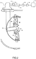
FIG. 2 is a side view of a combustor bulkhead and fuel injection system constructed in accordance with an embodiment. -
FIG. 3 is schematic representation of the fuel injection system constructed in accordance with an embodiment. -
FIG. 4 is a flowchart depicting a sample sequence of actions and events which may be practiced in accordance with an embodiment. -
FIG. 5 is a flowchart depicting a process flow according to an embodiment. - It is to be noted that the appended drawings illustrate only exemplary embodiments and are therefore not to be considered limiting with respect to the scope of the disclosure or claims. Rather, the concepts of the present disclosure may apply within other equally effective embodiments. Moreover, the drawings are not necessarily to scale, emphasis generally being placed upon illustrating the principles of certain embodiments.
-
Figure 1 schematically illustrates agas turbine engine 20. Thegas turbine engine 20 is disclosed herein as a two-spool turbofan that generally incorporates afan section 22, acompressor section 24, acombustor section 26 and aturbine section 28. Alternative engines might include an augmentor section (not shown) among other systems or features. Thefan section 22 drives air along a bypass flow path B in a bypass duct defined within anacelle 15, while thecompressor section 24 drives air along a core flow path C for compression and communication into thecombustor section 26 then expansion through theturbine section 28. Although depicted as a two-spool turbofan gas turbine engine in the disclosed non-limiting embodiment, it should be understood that the concepts described herein are not limited to use with two-spool turbofans as the teachings may be applied to other types of turbine engines including three-spool architectures. - The
exemplary engine 20 generally includes alow speed spool 30 and ahigh speed spool 32 mounted for rotation about an engine central longitudinal axis A relative to an enginestatic structure 36 viaseveral bearing systems 38. It should be understood thatvarious bearing systems 38 at various locations may alternatively or additionally be provided, and the location ofbearing systems 38 may be varied as appropriate to the application. - The
low speed spool 30 generally includes aninner shaft 40 that interconnects afan 42, alow pressure compressor 44 and alow pressure turbine 46. Theinner shaft 40 is connected to thefan 42 through a speed change mechanism, which in exemplarygas turbine engine 20 is illustrated as a gearedarchitecture 48 to drive thefan 42 at a lower speed than thelow speed spool 30. Thehigh speed spool 32 includes anouter shaft 50 that interconnects ahigh pressure compressor 52 andhigh pressure turbine 54. Acombustor 56 is arranged inexemplary gas turbine 20 between thehigh pressure compressor 52 and thehigh pressure turbine 54. Amid-turbine frame 57 of the enginestatic structure 36 is arranged generally between thehigh pressure turbine 54 and thelow pressure turbine 46. Themid-turbine frame 57 furthersupports bearing systems 38 in theturbine section 28. Theinner shaft 40 and theouter shaft 50 are concentric and rotate via bearingsystems 38 about the engine central longitudinal axis A which is collinear with their longitudinal axes. - The core airflow is compressed by the
low pressure compressor 44 then thehigh pressure compressor 52, mixed and burned with fuel in thecombustor 56, then expanded over thehigh pressure turbine 54 andlow pressure turbine 46. Themid-turbine frame 57 includesairfoils 59 which are in the core airflow path C. Theturbines low speed spool 30 andhigh speed spool 32 in response to the expansion. It will be appreciated that each of the positions of thefan section 22,compressor section 24,combustor section 26,turbine section 28, and fandrive gear system 48 may be varied. For example,gear system 48 may be located aft ofcombustor section 26 or even aft ofturbine section 28, andfan section 22 may be positioned forward or aft of the location ofgear system 48. - The
gas turbine engine 20 in one example is a high-bypass geared aircraft engine. In a further example, thegas turbine engine 20 bypass ratio is greater than about six (6), with an example embodiment being greater than about ten (10), the gearedarchitecture 48 is an epicyclic gear train, such as a planetary gear system or other gear system, with a gear reduction ratio of greater than about 2.3 and thelow pressure turbine 46 has a pressure ratio that is greater than about five. In one disclosed embodiment, thegas turbine engine 20 bypass ratio is greater than about ten (10:1), the fan diameter is significantly larger than that of thelow pressure compressor 44, and thelow pressure turbine 46 has a pressure ratio that is greater than about five 5:1.Low pressure turbine 46 pressure ratio is pressure measured prior to inlet oflow pressure turbine 46 as related to the pressure at the outlet of thelow pressure turbine 46 prior to an exhaust nozzle. The gearedarchitecture 48 may be an epicycle gear train, such as a planetary gear system or other gear system, with a gear reduction ratio of greater than about 2.3:1. It should be understood, however, that the above parameters are only exemplary of one embodiment of a geared architecture engine and that the present invention is applicable to other gas turbine engines including direct drive turbofans. - A significant amount of thrust is provided by the bypass flow B due to the high bypass ratio. The
fan section 22 of thegas turbine engine 20 is designed for a particular flight condition -- typically cruise at about 0.8 Mach and about 10668 meters (35000 feet). - The flight condition of 0.8 Mach and: 10668 meters (35000 feet), with the engine at its best fuel consumption - also known as "bucket cruise Thrust Specific Fuel Consumption ('TSFC')" - is the industry standard parameter of lbm of fuel being burned divided by lbf of thrust the engine produces at that minimum point. "Low fan pressure ratio" is the pressure ratio across the fan blade alone, without a Fan Exit Guide Vane ("FEGV") system. The low fan pressure ratio as disclosed herein according to one non-limiting embodiment is less than about 1.45. "Low corrected fan tip speed" is the actual fan tip speed in m/sec (ft/sec) divided by an industry standard temperature correction of [(Tram K) / 288,167 K)]0.5 ([(Tram °R) / (518.7 °R)]0.5 The "Low corrected fan tip speed" as disclosed herein according to one non-limiting embodiment is less than about 350,52 m/sec (1150 ft/sec). The
gas turbine engine 20 may further include anRPM sensor 62 for monitoring a rotational speed. - A
fuel injection system 70 is used to supply fuel to thecombustor 56 as shown inFIG. 2 . In operation, thegas turbine engine 20 requires continuous combustion of a fuel-air mixture, and a corresponding continuous supply of fuel. Afuel supply 72 and afuel pump 74 are in fluid communication with thefuel injection system 70 via aprimary fuel line 76 and asecondary fuel line 78. Aflow meter 80 is included to monitor a fuel flow rate. Theflow meter 80 may be located within or near thefuel supply 72,fuel pump 74 or at another point along thefuel injection system 70. - The
fuel injection system 70 may include afuel injector tip 82 located near the forward end of thecombustor 56. Thefuel injector tip 82 may include various means for injecting fuel into thecombustor 56. Theprimary fuel line 76 and thesecondary fuel line 78 may each travel through, or near, thefuel injector tip 82. - The
primary fuel line 76 includes anatomizer 84 for injecting atomized fuel into thecombustor 56. Thesecondary fuel line 78 includes ajet 86 for injecting fuel into thecombustor 56. Theprimary fuel line 76 and thesecondary fuel line 78 terminate at theatomizer 84 and thejet 86, respectively. As will be described in detail below, aflow divider valve 90 is also located on thesecondary fuel line 78. - The
atomizer 84 andjet 86 are both housed in adual passage injector 96, as shown inFIG. 2 . In addition to varying degrees of fuel atomization during injection, theatomizer 84 andjet 86 may each inject fuel into the combustor at a different angle relative to thedual passage injector 96. In particular, theatomizer 84 may inject fuel angled to be immediately combusted within thecombustor 56, while thejet 86 may inject fuel angled to interact with anairflow 98 prior to combustion. - For efficient continued combustion, various properties of the injected fuel may be controlled. One of these properties is the size of a fuel droplet injected into the
combustor 56. Smaller droplets enable an increased total fuel surface area, aiding combustion efficiency. However, reducing the size of the droplets may introduce disadvantages including an increased pressure requirement, reduced fuel flow or more expensive components. Accordingly, a balance of larger and smaller droplets may be injected to thecombustor 56. - During operation, a
gas turbine engine 20 may transition between steady states. Steady states may include an inactive state, a ground idle power state and a higher power state. The higher power state may be a bleed air power state, a takeoff power state, a steady flight power state or another steady power state. Alternatively, thegas turbine engine 20 may transition among higher power states. The inactive state may involve thecombustor 56 not continually combusting a fuel-air mixture, whereas ground idle power and higher power states may involve thecombustor 56 continually combusting a fuel-air mixture. - The smaller droplets may provide fuel to the
combustor 56 in a form sufficiently atomized forgas turbine engine 20 transition in all conditions. Theatomizer 84 may inject fuel having this smaller droplet size into thecombustor 56. - Alternatively, larger droplets may provide fuel to the
combustor 56 that requires an interaction with theairflow 98 before being sufficiently atomized forgas turbine engine 20 transitioning in all conditions. Thisairflow 98, which may come from anair passage 92, may be insufficient prior to transition to guarantee a successful transition. Theair passage 92 may be aswirler 94, or another type of vent, hole or passage. Thejet 86 may inject fuel into thecombustor 56 having this larger droplet size. - To ensure successful
gas turbine engine 20 transitioning in all conditions, differing pressures for eachfuel line secondary fuel line 78 during transition, but before thegas turbine engine 20 reaches a steady state. - In limiting the pressure in the
secondary fuel line 78, a greater percentage of total fuel injected into thecombustor 56 may come through theprimary fuel line 76 andatomizer 84 than through thesecondary fuel line 78 andjet 86. The greater percentage may be sufficient to allowgas turbine engine 20 transition during all conditions. This fuel delivery configuration may be called a first fuel delivery mode, and it may be understood that this first fuel delivery mode employs a first delta pressure condition as the fuel pressure in the primary andsecondary fuel lines flow divider valve 90 is used to change a fuel pressure in thesecondary fuel line 78. Theflow divider valve 90 is a pressure modulator having more than one position and comprises a solenoid valve. - Another fuel delivery configuration could also limit the pressure in the
secondary fuel line 78, and a greater percentage of total fuel injected into thecombustor 56 may come through theprimary fuel line 76 andatomizer 84 than through thesecondary fuel line 78 andjet 86. However, this fuel delivery configuration may be called a second fuel delivery mode, and it may be understood that this second fuel delivery mode employs a second delta pressure condition as the fuel pressure in the primary andsecondary fuel lines flow divider valve 90 may be used to change a fuel pressure in thesecondary fuel line 78, and theflow divider valve 90 may also be employed to change between the first fuel delivery mode and the second fuel delivery mode. - In another embodiment, the second fuel delivery mode could include equal fuel pressures for the primary and
secondary fuel lines secondary fuel lines - A
control system 100, which may include amicroprocessor 102 and amemory 104, is in electronic communication with theRPM sensor 62,fuel pump 74,flow meter 80 and flowdivider valve 90, as shown inFIG. 3 . When operating in either fuel delivery mode, thecontrol system 100 may detect a particular RPM reading from theRPM sensor 62 and a particular fuel flow rate from theflow meter 80. If the RPM reading is too low given the fuel flow rate, thecontrol system 100 may direct thefuel pump 74 to increase the total fuel flow rate to thecombustor 56. - When operating in the first fuel delivery mode, the decreased pressure in the
secondary fuel line 78 may not allow enough fuel flow to sufficiently fill thesecondary fuel line 78. If thesecondary fuel line 78 is not sufficiently filled, and an increased fuel flow rate is commanded by thecontrol system 100, the additional fuel supplied will simply fill thesecondary fuel line 78 rather than be combusted in thegas turbine engine 20. This may produce an inconsistency between the actualgas turbine engine 20 power output and the expectedgas turbine engine 20 power output for the amount of fuel being injected, particularly if a steady state were entered while operating in the first fuel delivery mode. In response to the lack of actual power being produced, thecontrol system 100 may command a still higher fuel flow rate, possibly leading to improper fuel regulation. - However, operating in the second fuel delivery mode may allow the
secondary fuel line 78 to be sufficiently filled, eliminating the filling of thesecondary fuel line 78 in response to an increased fuel flow, as shown inFIG. 4 . As the first fuel delivery mode may guarantee a successful transition between steady states in all conditions, it may be employed during transition, as shown inblock 200. After transition, as shown inblock 202, but before thegas turbine engine 20 reaches a steady state, thecontrol system 100 can direct theflow divider valve 90 to employ the second fuel delivery mode, as shown inblock 204. This allows successful transition in all conditions, but avoids the possibility of steady state, or increasing power mode, operations with an insufficiently filledsecondary fuel line 78, as shown inblock 206. - The second delivery mode is employed after the first fuel delivery mode but during the transition and before the gas turbine engine 10 reaches a steady state.
- The present disclosure allows for the elimination of individual fuel injector valves, while providing a system and process for successfully transitioning a
gas turbine engine 20 in all conditions. The present disclosure also helps avoid operation during a steady state, or increasing power mode, with insufficiently filledsecondary fuel line 78. The elimination of individual fuel injector valves may reduce the total complexity and number of parts of thefuel injection system 70. In turn, this reduction may lead to decreased build, acquisition and maintenance costs, reduced system weight and improved system packaging. -
FIG. 5 depicts a method for scheduling fuel delivery in a gas turbine engine and a method of delivering fuel to a gas turbine engine according to an embodiment. The method comprises operating the gas turbine engine in a first fuel delivery mode during transition between steady states, a first delta pressure condition existing between a primary fuel line and a secondary fuel line in the firstfuel delivery mode 220, operating the gas turbine engine in a second fuel delivery mode before the gas turbine engine enters a steady state, a second delta pressure condition existing between the primary fuel line and the secondary fuel line in the second fuel delivery mode, the first delta pressure condition having a larger pressure difference than the seconddelta pressure condition 222, and changing between the first fuel delivery mode and the second fuel delivery mode using a flow divider valve, the flow divider valve being a pressure modulator on the secondary fuel line having more than oneposition 224. - While the present disclosure has shown and described details of exemplary embodiments, it will be understood by one skilled in the art that various changes in detail may be effected therein without departing from the spirit and scope of the disclosure as defined by claims supported by the written description and drawings. Further, where these exemplary embodiments (and other related derivations) are described with reference to a certain number of elements it will be understood that other exemplary embodiments may be practiced utilizing either less than or more than the certain number of elements.
- In operation, the present disclosure sets forth a fuel delivery schedule for a gas turbine engine which can find industrial applicability in a variety of settings. For example, the disclosure may be advantageously employed by gas turbine engines 10 in aviation, naval and industrial settings. More specifically, the fuel delivery schedule for a gas turbine engine can be used to enable successful transition in all conditions, but avoid the possibility of steady state, or increasing power mode, operations with an insufficiently filled
secondary fuel line 78. - The present disclosure allows for the elimination of individual fuel injector valves, while providing a system and process for successfully transitioning a
gas turbine engine 20 in all conditions. The elimination of individual fuel injector valves may reduce the total complexity and number of parts of thefuel injection system 70. In turn, this reduction may lead to decreased build, acquisition and maintenance costs, reduced system weight and improved system packaging. - The fuel delivery schedule for a gas turbine engine of the present disclosure contributes to a gas turbine engine's 10 continued and efficient operation. The disclosed system may be original equipment on new gas turbine engines 10, or added as a retrofit to existing gas turbine engines 10.
Claims (5)
- A gas turbine engine (20), comprising:a compressor (24) for compressing an airflow;a combustor (56) downstream of the compressor (24);a turbine (28) downstream of the combustor (56);an RPM sensor (62) for monitoring a rotational speed of the gas turbine engine; anda fuel injection system (70) comprising:a primary fuel line (76), wherein the primary fuel line (76) includes an atomizer (84) for injecting fuel into the combustor (56);a secondary fuel line (78), wherein the secondary fuel line (78) includes a jet (86) for injecting fuel into the combustor (56);a dual passage injector (96), wherein each of the primary fuel line (76) and the secondary fuel line (78) terminate within the dual passage injector (96) and inject fuel into the combustor (56), the dual passage injector (96) including the atomizer (84) of the primary fuel line (76) and the jet (86) of the secondary fuel line (78);a fuel pump (74);a fuel supply (72);a flow divider valve (90) located on the secondary fuel line (78), wherein the flow divider valve (90) is a solenoid valve having more than one position, and the flow divider valve (90) is used to alter a fuel pressure in the secondary fuel line (78);a flow meter (80) for monitoring a fuel flow rate; anda control system (100) in electronic communication with the fuel pump (74), the RPM sensor (62), the flow meter (80) and the flow divider valve (90), the control system (100) adapted to operate the flow divider valve (90) in a first fuel delivery mode including a first delta pressure condition between the primary fuel line (76) and the secondary fuel line (78), the control system (100) adapted to further operate the flow divider valve (90) in a second fuel delivery mode including a second delta pressure condition between the primary fuel line (76) and the secondary fuel line (78);wherein the control system (100) is adapted to command the flow divider valve (90) to execute a fuel schedule employing the first fuel delivery mode during a transition between steady states and subsequently employing the second fuel delivery mode before the gas turbine engine enters a steady state but during the transition.
- The fuel injection system (70) of claim 1, wherein the first delta pressure condition has a larger pressure difference than the second delta pressure condition.
- The fuel injection system (70) of any preceding claim, wherein the transition between steady states is between an inactive state and a ground idle power state.
- The fuel injection system (70) of any of claims 1 or 2, wherein the transition between steady states is between a ground idle power state and a higher power state.
- A method of delivering fuel to a gas turbine engine (20), comprising;injecting fuel into a combustor (56) of the gas turbine engine (20) from a fuel supply (72) using a primary fuel line (76) terminating within a dual passage injector (96), wherein the primary fuel line (76) includes an atomizer (84) for injecting fuel into the combustor (56);injecting fuel into the combustor (56) of the gas turbine engine (20) from a fuel supply (72) using a secondary fuel line (78) terminating within the dual passage injector (96), wherein the secondary fuel line (78) includes a jet (86) for injecting fuel into the combustor (56);altering the fuel pressure in the secondary fuel line (78) using a flow divider valve (90), the flow divider valve (90) being a solenoid valve having more than one position;monitoring a rotational speed of the gas turbine engine using an RPM sensor (62);monitoring a fuel flow rate using a flow meter (80);controlling the operation of the flow divider valve (90) using a control system (100), the control system (100) being in electronic communication with the fuel pump (74), RPM sensor (62), the flow meter (80) and the flow divider valve (90);operating, using the controller system (100), the flow divider valve (90) in a first fuel delivery mode during a transition between steady states, a first delta pressure condition existing between a primary fuel line (76) and a secondary fuel line (78) in the first fuel delivery mode, andsubsequently operating, using the controller system (100), the flow divider valve (90) in a second fuel delivery mode before the gas turbine engine enters a steady state but during the transition, a second delta pressure condition existing between the primary fuel line (76) and the secondary fuel line (78) in the second fuel delivery mode, the first delta pressure condition having a larger pressure difference than the second delta pressure condition.
Applications Claiming Priority (1)
| Application Number | Priority Date | Filing Date | Title |
|---|---|---|---|
| US201462090225P | 2014-12-10 | 2014-12-10 |
Publications (2)
| Publication Number | Publication Date |
|---|---|
| EP3032071A1 EP3032071A1 (en) | 2016-06-15 |
| EP3032071B1 true EP3032071B1 (en) | 2020-12-02 |
Family
ID=55022260
Family Applications (1)
| Application Number | Title | Priority Date | Filing Date |
|---|---|---|---|
| EP15198720.3A Active EP3032071B1 (en) | 2014-12-10 | 2015-12-09 | Fuel schedule for robust gas turbine engine transition between steady states |
Country Status (2)
| Country | Link |
|---|---|
| US (1) | US20160169120A1 (en) |
| EP (1) | EP3032071B1 (en) |
Families Citing this family (1)
| Publication number | Priority date | Publication date | Assignee | Title |
|---|---|---|---|---|
| GB202205355D0 (en) * | 2022-04-12 | 2022-05-25 | Rolls Royce Plc | Gas turbine operation |
Family Cites Families (7)
| Publication number | Priority date | Publication date | Assignee | Title |
|---|---|---|---|---|
| US5329759A (en) * | 1993-06-30 | 1994-07-19 | Pratt & Whitney Canada, Inc. | Method for regulating fuel flow in a gas turbine engine |
| US6161387A (en) * | 1998-10-30 | 2000-12-19 | United Technologies Corporation | Multishear fuel injector |
| US6968699B2 (en) * | 2003-05-08 | 2005-11-29 | General Electric Company | Sector staging combustor |
| EP2071156B1 (en) * | 2007-12-10 | 2013-11-06 | Alstom Technology Ltd | Fuel distribution system for a gas turbine with multistage burner arrangement |
| US8820087B2 (en) * | 2008-09-08 | 2014-09-02 | Siemens Energy, Inc. | Method and system for controlling fuel to a dual stage nozzle |
| FR2969703B1 (en) * | 2010-12-23 | 2014-11-28 | Snecma | FUEL SUPPLY METHOD OF A TURBOMACHINE |
| US8590310B2 (en) * | 2012-03-27 | 2013-11-26 | Hamilton Sundstrand Corporation | Passive equilization flow divider valve |
-
2015
- 2015-11-03 US US14/930,743 patent/US20160169120A1/en not_active Abandoned
- 2015-12-09 EP EP15198720.3A patent/EP3032071B1/en active Active
Non-Patent Citations (1)
| Title |
|---|
| None * |
Also Published As
| Publication number | Publication date |
|---|---|
| EP3032071A1 (en) | 2016-06-15 |
| US20160169120A1 (en) | 2016-06-16 |
Similar Documents
| Publication | Publication Date | Title |
|---|---|---|
| EP3296543B1 (en) | Gas turbine engine with intercooled cooling air and turbine drive | |
| US9863322B2 (en) | Selectively deoxygenated stored fuel system | |
| EP2947278B1 (en) | Geared turbofan with high speed generator | |
| EP3109434B1 (en) | Bypass duct heat exchanger with controlled fan | |
| EP2809921B1 (en) | Gas turbine engine with compressor inlet guide vane positioned for starting | |
| EP3348810B1 (en) | Injection cooled cooling air system for a gas turbine engine and a corresponding method | |
| JP2007182884A (en) | Cooling system for controlling cooling air temperature of gas turbine engine and gas turbine engine assembly | |
| EP3115298B1 (en) | Nacelle anti-ice system and method with equalized flow | |
| US20170074112A1 (en) | Active clearance control for gas turbine engine | |
| EP2809924B1 (en) | Gas turbine engine with variable area fan nozzle positioned for starting | |
| CN109028150A (en) | For rotating the effervesce atomization structure and operating method of pinking propulsion system | |
| US11506128B2 (en) | Hydraulic starter assembly for a gas turbine engine | |
| EP2959132B1 (en) | Self-purging fuel injector system for a gas turbine engine | |
| EP3032071B1 (en) | Fuel schedule for robust gas turbine engine transition between steady states | |
| US10731502B2 (en) | High pressure compressor rotor thermal conditioning using outer diameter gas extraction | |
| EP3054124B1 (en) | Accumulator assisted gas turbine engine start system and methods therefor | |
| EP3730766A1 (en) | Method for reducing fuel nozzle coking in a gas turbine engine | |
| EP3056722B1 (en) | Turbine engine structure with oxidizer enhanced mode | |
| US20160010866A1 (en) | Aerating fuel injector system for a gas turbine engine |
Legal Events
| Date | Code | Title | Description |
|---|---|---|---|
| PUAI | Public reference made under article 153(3) epc to a published international application that has entered the european phase |
Free format text: ORIGINAL CODE: 0009012 |
|
| AK | Designated contracting states |
Kind code of ref document: A1 Designated state(s): AL AT BE BG CH CY CZ DE DK EE ES FI FR GB GR HR HU IE IS IT LI LT LU LV MC MK MT NL NO PL PT RO RS SE SI SK SM TR |
|
| AX | Request for extension of the european patent |
Extension state: BA ME |
|
| RAP1 | Party data changed (applicant data changed or rights of an application transferred) |
Owner name: UNITED TECHNOLOGIES CORPORATION |
|
| STAA | Information on the status of an ep patent application or granted ep patent |
Free format text: STATUS: REQUEST FOR EXAMINATION WAS MADE |
|
| 17P | Request for examination filed |
Effective date: 20161215 |
|
| RBV | Designated contracting states (corrected) |
Designated state(s): AL AT BE BG CH CY CZ DE DK EE ES FI FR GB GR HR HU IE IS IT LI LT LU LV MC MK MT NL NO PL PT RO RS SE SI SK SM TR |
|
| STAA | Information on the status of an ep patent application or granted ep patent |
Free format text: STATUS: EXAMINATION IS IN PROGRESS |
|
| 17Q | First examination report despatched |
Effective date: 20190513 |
|
| GRAP | Despatch of communication of intention to grant a patent |
Free format text: ORIGINAL CODE: EPIDOSNIGR1 |
|
| STAA | Information on the status of an ep patent application or granted ep patent |
Free format text: STATUS: GRANT OF PATENT IS INTENDED |
|
| INTG | Intention to grant announced |
Effective date: 20200110 |
|
| GRAJ | Information related to disapproval of communication of intention to grant by the applicant or resumption of examination proceedings by the epo deleted |
Free format text: ORIGINAL CODE: EPIDOSDIGR1 |
|
| STAA | Information on the status of an ep patent application or granted ep patent |
Free format text: STATUS: EXAMINATION IS IN PROGRESS |
|
| INTC | Intention to grant announced (deleted) | ||
| GRAP | Despatch of communication of intention to grant a patent |
Free format text: ORIGINAL CODE: EPIDOSNIGR1 |
|
| STAA | Information on the status of an ep patent application or granted ep patent |
Free format text: STATUS: GRANT OF PATENT IS INTENDED |
|
| INTG | Intention to grant announced |
Effective date: 20200626 |
|
| GRAS | Grant fee paid |
Free format text: ORIGINAL CODE: EPIDOSNIGR3 |
|
| GRAA | (expected) grant |
Free format text: ORIGINAL CODE: 0009210 |
|
| STAA | Information on the status of an ep patent application or granted ep patent |
Free format text: STATUS: THE PATENT HAS BEEN GRANTED |
|
| AK | Designated contracting states |
Kind code of ref document: B1 Designated state(s): AL AT BE BG CH CY CZ DE DK EE ES FI FR GB GR HR HU IE IS IT LI LT LU LV MC MK MT NL NO PL PT RO RS SE SI SK SM TR |
|
| REG | Reference to a national code |
Ref country code: GB Ref legal event code: FG4D |
|
| REG | Reference to a national code |
Ref country code: AT Ref legal event code: REF Ref document number: 1341179 Country of ref document: AT Kind code of ref document: T Effective date: 20201215 Ref country code: CH Ref legal event code: EP |
|
| REG | Reference to a national code |
Ref country code: DE Ref legal event code: R096 Ref document number: 602015062834 Country of ref document: DE |
|
| REG | Reference to a national code |
Ref country code: IE Ref legal event code: FG4D |
|
| RAP2 | Party data changed (patent owner data changed or rights of a patent transferred) |
Owner name: RAYTHEON TECHNOLOGIES CORPORATION |
|
| PG25 | Lapsed in a contracting state [announced via postgrant information from national office to epo] |
Ref country code: FI Free format text: LAPSE BECAUSE OF FAILURE TO SUBMIT A TRANSLATION OF THE DESCRIPTION OR TO PAY THE FEE WITHIN THE PRESCRIBED TIME-LIMIT Effective date: 20201202 Ref country code: RS Free format text: LAPSE BECAUSE OF FAILURE TO SUBMIT A TRANSLATION OF THE DESCRIPTION OR TO PAY THE FEE WITHIN THE PRESCRIBED TIME-LIMIT Effective date: 20201202 Ref country code: NO Free format text: LAPSE BECAUSE OF FAILURE TO SUBMIT A TRANSLATION OF THE DESCRIPTION OR TO PAY THE FEE WITHIN THE PRESCRIBED TIME-LIMIT Effective date: 20210302 Ref country code: GR Free format text: LAPSE BECAUSE OF FAILURE TO SUBMIT A TRANSLATION OF THE DESCRIPTION OR TO PAY THE FEE WITHIN THE PRESCRIBED TIME-LIMIT Effective date: 20210303 |
|
| REG | Reference to a national code |
Ref country code: NL Ref legal event code: MP Effective date: 20201202 |
|
| REG | Reference to a national code |
Ref country code: AT Ref legal event code: MK05 Ref document number: 1341179 Country of ref document: AT Kind code of ref document: T Effective date: 20201202 |
|
| PG25 | Lapsed in a contracting state [announced via postgrant information from national office to epo] |
Ref country code: BG Free format text: LAPSE BECAUSE OF FAILURE TO SUBMIT A TRANSLATION OF THE DESCRIPTION OR TO PAY THE FEE WITHIN THE PRESCRIBED TIME-LIMIT Effective date: 20210302 Ref country code: SE Free format text: LAPSE BECAUSE OF FAILURE TO SUBMIT A TRANSLATION OF THE DESCRIPTION OR TO PAY THE FEE WITHIN THE PRESCRIBED TIME-LIMIT Effective date: 20201202 Ref country code: PL Free format text: LAPSE BECAUSE OF FAILURE TO SUBMIT A TRANSLATION OF THE DESCRIPTION OR TO PAY THE FEE WITHIN THE PRESCRIBED TIME-LIMIT Effective date: 20201202 Ref country code: LV Free format text: LAPSE BECAUSE OF FAILURE TO SUBMIT A TRANSLATION OF THE DESCRIPTION OR TO PAY THE FEE WITHIN THE PRESCRIBED TIME-LIMIT Effective date: 20201202 |
|
| PG25 | Lapsed in a contracting state [announced via postgrant information from national office to epo] |
Ref country code: NL Free format text: LAPSE BECAUSE OF FAILURE TO SUBMIT A TRANSLATION OF THE DESCRIPTION OR TO PAY THE FEE WITHIN THE PRESCRIBED TIME-LIMIT Effective date: 20201202 Ref country code: HR Free format text: LAPSE BECAUSE OF FAILURE TO SUBMIT A TRANSLATION OF THE DESCRIPTION OR TO PAY THE FEE WITHIN THE PRESCRIBED TIME-LIMIT Effective date: 20201202 |
|
| REG | Reference to a national code |
Ref country code: LT Ref legal event code: MG9D |
|
| PG25 | Lapsed in a contracting state [announced via postgrant information from national office to epo] |
Ref country code: SK Free format text: LAPSE BECAUSE OF FAILURE TO SUBMIT A TRANSLATION OF THE DESCRIPTION OR TO PAY THE FEE WITHIN THE PRESCRIBED TIME-LIMIT Effective date: 20201202 Ref country code: PT Free format text: LAPSE BECAUSE OF FAILURE TO SUBMIT A TRANSLATION OF THE DESCRIPTION OR TO PAY THE FEE WITHIN THE PRESCRIBED TIME-LIMIT Effective date: 20210405 Ref country code: RO Free format text: LAPSE BECAUSE OF FAILURE TO SUBMIT A TRANSLATION OF THE DESCRIPTION OR TO PAY THE FEE WITHIN THE PRESCRIBED TIME-LIMIT Effective date: 20201202 Ref country code: LT Free format text: LAPSE BECAUSE OF FAILURE TO SUBMIT A TRANSLATION OF THE DESCRIPTION OR TO PAY THE FEE WITHIN THE PRESCRIBED TIME-LIMIT Effective date: 20201202 Ref country code: SM Free format text: LAPSE BECAUSE OF FAILURE TO SUBMIT A TRANSLATION OF THE DESCRIPTION OR TO PAY THE FEE WITHIN THE PRESCRIBED TIME-LIMIT Effective date: 20201202 Ref country code: EE Free format text: LAPSE BECAUSE OF FAILURE TO SUBMIT A TRANSLATION OF THE DESCRIPTION OR TO PAY THE FEE WITHIN THE PRESCRIBED TIME-LIMIT Effective date: 20201202 Ref country code: CZ Free format text: LAPSE BECAUSE OF FAILURE TO SUBMIT A TRANSLATION OF THE DESCRIPTION OR TO PAY THE FEE WITHIN THE PRESCRIBED TIME-LIMIT Effective date: 20201202 |
|
| REG | Reference to a national code |
Ref country code: CH Ref legal event code: PL |
|
| PG25 | Lapsed in a contracting state [announced via postgrant information from national office to epo] |
Ref country code: AT Free format text: LAPSE BECAUSE OF FAILURE TO SUBMIT A TRANSLATION OF THE DESCRIPTION OR TO PAY THE FEE WITHIN THE PRESCRIBED TIME-LIMIT Effective date: 20201202 |
|
| REG | Reference to a national code |
Ref country code: DE Ref legal event code: R097 Ref document number: 602015062834 Country of ref document: DE Ref country code: BE Ref legal event code: MM Effective date: 20201231 |
|
| PG25 | Lapsed in a contracting state [announced via postgrant information from national office to epo] |
Ref country code: IS Free format text: LAPSE BECAUSE OF FAILURE TO SUBMIT A TRANSLATION OF THE DESCRIPTION OR TO PAY THE FEE WITHIN THE PRESCRIBED TIME-LIMIT Effective date: 20210402 Ref country code: MC Free format text: LAPSE BECAUSE OF FAILURE TO SUBMIT A TRANSLATION OF THE DESCRIPTION OR TO PAY THE FEE WITHIN THE PRESCRIBED TIME-LIMIT Effective date: 20201202 |
|
| PLBE | No opposition filed within time limit |
Free format text: ORIGINAL CODE: 0009261 |
|
| STAA | Information on the status of an ep patent application or granted ep patent |
Free format text: STATUS: NO OPPOSITION FILED WITHIN TIME LIMIT |
|
| PG25 | Lapsed in a contracting state [announced via postgrant information from national office to epo] |
Ref country code: AL Free format text: LAPSE BECAUSE OF FAILURE TO SUBMIT A TRANSLATION OF THE DESCRIPTION OR TO PAY THE FEE WITHIN THE PRESCRIBED TIME-LIMIT Effective date: 20201202 Ref country code: IT Free format text: LAPSE BECAUSE OF FAILURE TO SUBMIT A TRANSLATION OF THE DESCRIPTION OR TO PAY THE FEE WITHIN THE PRESCRIBED TIME-LIMIT Effective date: 20201202 Ref country code: IE Free format text: LAPSE BECAUSE OF NON-PAYMENT OF DUE FEES Effective date: 20201209 Ref country code: LU Free format text: LAPSE BECAUSE OF NON-PAYMENT OF DUE FEES Effective date: 20201209 |
|
| 26N | No opposition filed |
Effective date: 20210903 |
|
| PG25 | Lapsed in a contracting state [announced via postgrant information from national office to epo] |
Ref country code: LI Free format text: LAPSE BECAUSE OF NON-PAYMENT OF DUE FEES Effective date: 20201231 Ref country code: SI Free format text: LAPSE BECAUSE OF FAILURE TO SUBMIT A TRANSLATION OF THE DESCRIPTION OR TO PAY THE FEE WITHIN THE PRESCRIBED TIME-LIMIT Effective date: 20201202 Ref country code: CH Free format text: LAPSE BECAUSE OF NON-PAYMENT OF DUE FEES Effective date: 20201231 Ref country code: DK Free format text: LAPSE BECAUSE OF FAILURE TO SUBMIT A TRANSLATION OF THE DESCRIPTION OR TO PAY THE FEE WITHIN THE PRESCRIBED TIME-LIMIT Effective date: 20201202 Ref country code: ES Free format text: LAPSE BECAUSE OF FAILURE TO SUBMIT A TRANSLATION OF THE DESCRIPTION OR TO PAY THE FEE WITHIN THE PRESCRIBED TIME-LIMIT Effective date: 20201202 |
|
| PG25 | Lapsed in a contracting state [announced via postgrant information from national office to epo] |
Ref country code: IS Free format text: LAPSE BECAUSE OF FAILURE TO SUBMIT A TRANSLATION OF THE DESCRIPTION OR TO PAY THE FEE WITHIN THE PRESCRIBED TIME-LIMIT Effective date: 20210402 Ref country code: TR Free format text: LAPSE BECAUSE OF FAILURE TO SUBMIT A TRANSLATION OF THE DESCRIPTION OR TO PAY THE FEE WITHIN THE PRESCRIBED TIME-LIMIT Effective date: 20201202 Ref country code: MT Free format text: LAPSE BECAUSE OF FAILURE TO SUBMIT A TRANSLATION OF THE DESCRIPTION OR TO PAY THE FEE WITHIN THE PRESCRIBED TIME-LIMIT Effective date: 20201202 Ref country code: CY Free format text: LAPSE BECAUSE OF FAILURE TO SUBMIT A TRANSLATION OF THE DESCRIPTION OR TO PAY THE FEE WITHIN THE PRESCRIBED TIME-LIMIT Effective date: 20201202 |
|
| PG25 | Lapsed in a contracting state [announced via postgrant information from national office to epo] |
Ref country code: MK Free format text: LAPSE BECAUSE OF FAILURE TO SUBMIT A TRANSLATION OF THE DESCRIPTION OR TO PAY THE FEE WITHIN THE PRESCRIBED TIME-LIMIT Effective date: 20201202 |
|
| PG25 | Lapsed in a contracting state [announced via postgrant information from national office to epo] |
Ref country code: BE Free format text: LAPSE BECAUSE OF NON-PAYMENT OF DUE FEES Effective date: 20201231 |
|
| P01 | Opt-out of the competence of the unified patent court (upc) registered |
Effective date: 20230520 |
|
| PGFP | Annual fee paid to national office [announced via postgrant information from national office to epo] |
Ref country code: GB Payment date: 20231124 Year of fee payment: 9 |
|
| PGFP | Annual fee paid to national office [announced via postgrant information from national office to epo] |
Ref country code: FR Payment date: 20231122 Year of fee payment: 9 Ref country code: DE Payment date: 20231121 Year of fee payment: 9 |