US20080098954A1 - CNC coolant nozzle - Google Patents
CNC coolant nozzle Download PDFInfo
- Publication number
- US20080098954A1 US20080098954A1 US11/546,789 US54678906A US2008098954A1 US 20080098954 A1 US20080098954 A1 US 20080098954A1 US 54678906 A US54678906 A US 54678906A US 2008098954 A1 US2008098954 A1 US 2008098954A1
- Authority
- US
- United States
- Prior art keywords
- swivel
- nozzle
- coolant
- adjustment plate
- variable position
- Prior art date
- Legal status (The legal status is an assumption and is not a legal conclusion. Google has not performed a legal analysis and makes no representation as to the accuracy of the status listed.)
- Granted
Links
Images


Classifications
-
- B—PERFORMING OPERATIONS; TRANSPORTING
- B24—GRINDING; POLISHING
- B24B—MACHINES, DEVICES, OR PROCESSES FOR GRINDING OR POLISHING; DRESSING OR CONDITIONING OF ABRADING SURFACES; FEEDING OF GRINDING, POLISHING, OR LAPPING AGENTS
- B24B55/00—Safety devices for grinding or polishing machines; Accessories fitted to grinding or polishing machines for keeping tools or parts of the machine in good working condition
- B24B55/02—Equipment for cooling the grinding surfaces, e.g. devices for feeding coolant
-
- B—PERFORMING OPERATIONS; TRANSPORTING
- B05—SPRAYING OR ATOMISING IN GENERAL; APPLYING FLUENT MATERIALS TO SURFACES, IN GENERAL
- B05B—SPRAYING APPARATUS; ATOMISING APPARATUS; NOZZLES
- B05B1/00—Nozzles, spray heads or other outlets, with or without auxiliary devices such as valves, heating means
- B05B1/14—Nozzles, spray heads or other outlets, with or without auxiliary devices such as valves, heating means with multiple outlet openings; with strainers in or outside the outlet opening
-
- B—PERFORMING OPERATIONS; TRANSPORTING
- B05—SPRAYING OR ATOMISING IN GENERAL; APPLYING FLUENT MATERIALS TO SURFACES, IN GENERAL
- B05B—SPRAYING APPARATUS; ATOMISING APPARATUS; NOZZLES
- B05B15/00—Details of spraying plant or spraying apparatus not otherwise provided for; Accessories
- B05B15/60—Arrangements for mounting, supporting or holding spraying apparatus
- B05B15/65—Mounting arrangements for fluid connection of the spraying apparatus or its outlets to flow conduits
- B05B15/652—Mounting arrangements for fluid connection of the spraying apparatus or its outlets to flow conduits whereby the jet can be oriented
-
- B—PERFORMING OPERATIONS; TRANSPORTING
- B23—MACHINE TOOLS; METAL-WORKING NOT OTHERWISE PROVIDED FOR
- B23Q—DETAILS, COMPONENTS, OR ACCESSORIES FOR MACHINE TOOLS, e.g. ARRANGEMENTS FOR COPYING OR CONTROLLING; MACHINE TOOLS IN GENERAL CHARACTERISED BY THE CONSTRUCTION OF PARTICULAR DETAILS OR COMPONENTS; COMBINATIONS OR ASSOCIATIONS OF METAL-WORKING MACHINES, NOT DIRECTED TO A PARTICULAR RESULT
- B23Q11/00—Accessories fitted to machine tools for keeping tools or parts of the machine in good working condition or for cooling work; Safety devices specially combined with or arranged in, or specially adapted for use in connection with, machine tools
- B23Q11/10—Arrangements for cooling or lubricating tools or work
- B23Q11/1076—Arrangements for cooling or lubricating tools or work with a cutting liquid nozzle specially adaptable to different kinds of machining operations
-
- Y—GENERAL TAGGING OF NEW TECHNOLOGICAL DEVELOPMENTS; GENERAL TAGGING OF CROSS-SECTIONAL TECHNOLOGIES SPANNING OVER SEVERAL SECTIONS OF THE IPC; TECHNICAL SUBJECTS COVERED BY FORMER USPC CROSS-REFERENCE ART COLLECTIONS [XRACs] AND DIGESTS
- Y10—TECHNICAL SUBJECTS COVERED BY FORMER USPC
- Y10T—TECHNICAL SUBJECTS COVERED BY FORMER US CLASSIFICATION
- Y10T408/00—Cutting by use of rotating axially moving tool
- Y10T408/44—Cutting by use of rotating axially moving tool with means to apply transient, fluent medium to work or product
-
- Y—GENERAL TAGGING OF NEW TECHNOLOGICAL DEVELOPMENTS; GENERAL TAGGING OF CROSS-SECTIONAL TECHNOLOGIES SPANNING OVER SEVERAL SECTIONS OF THE IPC; TECHNICAL SUBJECTS COVERED BY FORMER USPC CROSS-REFERENCE ART COLLECTIONS [XRACs] AND DIGESTS
- Y10—TECHNICAL SUBJECTS COVERED BY FORMER USPC
- Y10T—TECHNICAL SUBJECTS COVERED BY FORMER US CLASSIFICATION
- Y10T82/00—Turning
- Y10T82/10—Process of turning
-
- Y—GENERAL TAGGING OF NEW TECHNOLOGICAL DEVELOPMENTS; GENERAL TAGGING OF CROSS-SECTIONAL TECHNOLOGIES SPANNING OVER SEVERAL SECTIONS OF THE IPC; TECHNICAL SUBJECTS COVERED BY FORMER USPC CROSS-REFERENCE ART COLLECTIONS [XRACs] AND DIGESTS
- Y10—TECHNICAL SUBJECTS COVERED BY FORMER USPC
- Y10T—TECHNICAL SUBJECTS COVERED BY FORMER US CLASSIFICATION
- Y10T82/00—Turning
- Y10T82/16—Severing or cut-off
- Y10T82/16065—Combined with means to apply fluid
Definitions
- the invention relates generally to machine cutting fluid or coolant systems. More specifically, the invention relates to a nozzle assembly that varies the spray patterns of cutting machine coolant nozzles.
- Cutting fluid or coolant
- Metal cutting operations generate heat due to friction between a tool and a workpiece.
- the heat generated is from energy lost deforming the material and needs to be carried away.
- Water is a conductor of heat but is not stable at high temperatures, so stability is often achieved by making an emulsion of water with oil. The goal is to keep the workpiece at a stable temperature and maximize the life of the cutting tool by lubricating its working edge to reduce tip welding.
- the coolant stream must be aimed at the point where the cutting tool is removing metal.
- Manual systems require machine operators to constantly adjust the coolant systems to make sure coolant is aimed in the right position to flood the work zone. While coolant lines and nozzles are easy to adjust, having to make adjustments every time a tool change takes place is inefficient. It is also dangerous if an operator reaches into a machine with its spindle turning.
- What is desired is an apparatus that can be applied to an existing milling or grinding machine that targets coolant to a best location on a cutting tool in response to a machine program and allows machine operators to leave a machine untended for extended periods.
- variable position nozzle assembly for a milling or grinding machine where at least one nozzle is positioned to target coolant to the cutting area of a chosen tool.
- Each tool may have a different length or cutting or grinding surface width.
- Variable position nozzle assemblies for a machining tool.
- Variable position nozzle assemblies comprise a base plate having an aperture defining a center axis, at least one swivel nozzle coupled to the base plate, a static guide having an aperture corresponding to the base plate aperture and a number of radial slots corresponding to the number of swivel nozzles wherein the at least one swivel nozzle passes through, and an adjustment plate having an aperture corresponding to the base plate aperture and a number of linear slots corresponding to the number of swivel nozzles wherein the at least one swivel nozzle passes through and the adjustment plate is rotationally coupled to the static guide wherein the linear slots in conjunction with the static guide radial slots adjusts the at least one swivel nozzle towards the center axis or away from the center axis depending on a rotation position.
- FIG. 1 is an exemplary exploded perspective view of one embodiment of the invention.
- FIG. 2 is a side view of an exemplary swivel nozzle.
- FIG. 3 is a plan view of an exemplary base plate.
- FIG. 4A is a plan view of an exemplary static guide.
- FIG. 4B is a side sectional view of the exemplary static guide shown in FIG. 4A taken along line 4 B- 4 B.
- FIG. 5A is a plan view of an exemplary adjustment plate.
- FIG. 5B is a side sectional view of the exemplary adjustment plate shown in FIG. 5A taken along line 5 B- 5 B.
- FIG. 5C is a side view of the exemplary adjustment plate shown in FIG. 5A .
- FIG. 6A is a front view of the invention shown in FIG. 1 in a first position.
- FIG. 6B is a front view of the invention shown in FIG. 1 in a second position.
- Embodiments of the invention provide a variable position nozzle assembly for milling and grinding machines that targets coolant to specific locations along a tool axis using at least one nozzle.
- the base plate 103 provides a mounting surface for each swivel nozzle 105 n employed, and an attachment surface for securing the invention to a milling or grinding machine (not shown).
- the rotating part of the machine passes through a center aperture 115 along a center axis of the assembly 101 .
- the static guide 107 may be coupled to the base plate 101 using, for example, cap or machine screw hardware 117 .
- the base plate 103 and static guide 107 are generally circular in configuration, but may take on other shapes to fit specific applications.
- a preferred embodiment employs four swivel nozzles 105 1 , 105 2 , 105 3 , 105 4 .
- Shown in FIG. 2 is a swivel nozzle 105 n .
- Each swivel nozzle 105 n comprises a hollow threaded portion 201 , a hexagonal base 203 , and a ball joint with nozzle 205 .
- the ball joint allows for the nozzle 205 to negotiate a conical arc ⁇ .
- the arc ⁇ may be in a range of from 30° to 45°.
- a swivel nozzle 105 n height h 1 is defined by the hexagonal base 203 and ball joint length of a nozzle 205 .
- the base plate 103 may be radially divided by N where each swivel 105 n may be located as shown in FIG. 3 .
- each swivel 105 n may be located 90 ° apart. The angular difference between nozzle locations need not be equal and may be adjusted according to a specific application.
- the base plate 103 is drilled and tapped in matching outer diameter and thread pitch with the swivel nozzle hollow threaded portion 201 .
- the base plate thickness is sized such that the swivel nozzle 105 n threaded portion 201 passes through the base plate 101 and allows for coupling with a coolant fluid manifold (not shown) on an outer side of the base plate 103 . Coupling to the coolant fluid manifold may be via compression, swaged, or barbed tubing fittings.
- the static guide 107 covers the mounted swivel adapters 105 1 , 105 2 , 105 3 , 105 4 and is coupled to the base plate 103 .
- Each static guide slot 401 n is centered c above a swivel adapter 105 n .
- Each static guide slot 401 n length l 1 defines a maximum range of nozzle travel ⁇ in one plane.
- the static guide 107 internal depth h 2 is dimensioned to accommodate the swivel nozzle height h 1 , where h 2 >h 1 .
- the static guide slot 401 n allows for directing a nozzle 105 n in a radial direction.
- the adjustment plate 109 is mounted on the static plate 107 using shoulder cap or machine screw hardware 119 to allow for limited rotation.
- the adjustment plate is shown in FIGS. 5A , 5 B and 5 C.
- the edge of the adjustment plate 109 linear slot 503 n may be continuously chamfered, or radiused 507 on the outboard side.
- FIG. 6A shows the nozzles spraying coolant away from the center axis
- FIG. 6B shows the nozzles spraying coolant towards the center axis 115 .
- the stepper motor 111 and worm gear 113 provide the means to rotate the adjustment plate 109 from the first position 601 to the second position 602 and any intermediate position in response to a control signal (not shown).
- the positions of the swivel nozzles 105 n may therefore vary by ⁇ depending on the control signals sent to the stepper motor 111 by the CNC system of a machine the variable nozzle assembly is mounted on.
- CNC stands for computer numerical control and refers specifically to a computer controller that reads G-code instructions and drives the machine tool.
- CNC automation allows for flexibility in the way parts are held in the manufacturing process and the time required to change the machine to produce different components.
- a series of CNC machines may be combined into one station, refered to as a cell, to progressively machine a part requiring several operations.
- Most CNC machines today are controlled directly from files created by CAM (computer-aided manufacturing) software packages, so that a part or assembly can go directly from design to manufacturing without the need of producing a drafted paper drawing of the manufactured component.
- CAM computer-aided manufacturing
- CAM software generally requires an operator with much knowledge and skill of machining to select the milling machine and define the necessary parameters and strategies that will generate an effective tool path. Most software performs multi-surface machining. Most machining progresses through roughing, semi-finishing, and finishing depending on the workpiece material and the software available. All machining algorithms rely on finding valid cutter locations of the milling cutter against a workpiece. At each cutter location on the workpiece, the variable nozzle assembly 101 may adjust the position of the swivel nozzles 105 n .
- the stepper motor 111 varies the direction, or target, of the coolant stream in conjunction with the CNC program.
- the invention responds accordingly while the machine is running to software commands via the stepper motor 111 .
- the variable nozzle assembly 101 is coupled to the machine's head and is oriented so the coolant stream is aligned with a spindle centerline 115 .
- the system is designed for installation on any machining center with a standard coolant pump.
- the existing coolant pump for the machine may be plumbed to the variable nozzle assembly 101 .
- the CNC program directs tool changes and re-aims the variable nozzle assembly 101 automatically based on the chosen tool.
- the variable position nozzle assembly 101 adjusts its position in response to CNC instructions to target coolant to a best location.
- a location may be static or dynamic in response to the CNC program.
- the CNC system may derive a separate nozzle position program based on a workpiece program in conjunction with what tool from its tool changer is selected. Whenever a specific tool is placed in the machine spindle, the CNC program directs the variable position nozzle assembly 101 to target the flow of coolant to a specific location as work progresses.
- the variable position nozzle assembly 101 may target coolant to specific cutting tool locations in real-time in response to a CNC program as a workpiece is being machined. For example, if the variable position nozzle assembly 101 is coupled to a vertical mill, as a tool plunges into a workpiece, the nozzle assembly would maintain the coolant target to the exposed edge of the tool as directed by the CNC program. If a 6 inch drill bit were being used, and the mill has progressed to a depth of 2 inches, the variable position nozzle assembly 101 in response to the CNC program would continually move the coolant target from the drill tip along the drill shaft to where the drill bit enters the workpiece.
- variable position nozzle assembly 101 continually targets coolant to where the drill bit is exposed and where the coolant may flood the entry hole and remove swarfs and chips. If the nozzle position was static, positioned at the tip of a drill bit, as soon as the drill enters a workpiece, the coolant direction would no longer be on target since the tip is obscured by the workpiece. As machining progresses, the coolant target would move farther away from the entry hole, moving the coolant flooding region away from the entry hole.
- the variable position nozzle assembly 101 supports both carousel and double-arm type tool changers.
Landscapes
- Engineering & Computer Science (AREA)
- Mechanical Engineering (AREA)
- Auxiliary Devices For Machine Tools (AREA)
- Grinding-Machine Dressing And Accessory Apparatuses (AREA)
- Nozzles (AREA)
Abstract
Description
- The invention relates generally to machine cutting fluid or coolant systems. More specifically, the invention relates to a nozzle assembly that varies the spray patterns of cutting machine coolant nozzles.
- Milling and grinding machines need to have coolant directed to specific areas during cutting. Cutting fluid, or coolant, is liquid used to cool and lubricate the cutting edges of machine tools and the pieces they are shaping. It is pumped over the cutting site of machines such as lathes, milling machines, shapers, grinders and saws.
- Metal cutting operations generate heat due to friction between a tool and a workpiece. The heat generated is from energy lost deforming the material and needs to be carried away. Water is a conductor of heat but is not stable at high temperatures, so stability is often achieved by making an emulsion of water with oil. The goal is to keep the workpiece at a stable temperature and maximize the life of the cutting tool by lubricating its working edge to reduce tip welding.
- To ensure cutting edge cooling, the coolant stream must be aimed at the point where the cutting tool is removing metal. Manual systems require machine operators to constantly adjust the coolant systems to make sure coolant is aimed in the right position to flood the work zone. While coolant lines and nozzles are easy to adjust, having to make adjustments every time a tool change takes place is inefficient. It is also dangerous if an operator reaches into a machine with its spindle turning.
- The benefits of keeping coolant on target make substantial contributions to productivity. It minimizes the risk of damaging heat build-up in the workpiece or cutting tool thereby preserving tool life. It allows optimal feed rates and speeds to be applied more safely and flushes away swarfs and chips.
- What is desired is an apparatus that can be applied to an existing milling or grinding machine that targets coolant to a best location on a cutting tool in response to a machine program and allows machine operators to leave a machine untended for extended periods.
- The inventor has discovered that it would be desirable to have a variable position nozzle assembly for a milling or grinding machine where at least one nozzle is positioned to target coolant to the cutting area of a chosen tool. Each tool may have a different length or cutting or grinding surface width. The CNC program that directs tool motion and tool changes, re-aims the variable position nozzle assembly based on a chosen tool and the dynamic position of the tool as it traverses a workpiece.
- One aspect of the invention provides a variable position nozzle assembly for a machining tool. Variable position nozzle assemblies according to this aspect comprise a base plate having an aperture defining a center axis, at least one swivel nozzle coupled to the base plate, a static guide having an aperture corresponding to the base plate aperture and a number of radial slots corresponding to the number of swivel nozzles wherein the at least one swivel nozzle passes through, and an adjustment plate having an aperture corresponding to the base plate aperture and a number of linear slots corresponding to the number of swivel nozzles wherein the at least one swivel nozzle passes through and the adjustment plate is rotationally coupled to the static guide wherein the linear slots in conjunction with the static guide radial slots adjusts the at least one swivel nozzle towards the center axis or away from the center axis depending on a rotation position.
- The details of one or more embodiments of the invention are set forth in the accompanying drawings and the description below. Other features, objects, and advantages of the invention will be apparent from the description and drawings, and from the claims.
-
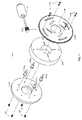
FIG. 1 is an exemplary exploded perspective view of one embodiment of the invention. -
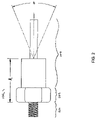
FIG. 2 is a side view of an exemplary swivel nozzle. -
FIG. 3 is a plan view of an exemplary base plate. -
FIG. 4A is a plan view of an exemplary static guide. -
FIG. 4B is a side sectional view of the exemplary static guide shown inFIG. 4A taken alongline 4B-4B. -
FIG. 5A is a plan view of an exemplary adjustment plate. -
FIG. 5B is a side sectional view of the exemplary adjustment plate shown inFIG. 5A taken alongline 5B-5B. -
FIG. 5C is a side view of the exemplary adjustment plate shown inFIG. 5A . -
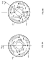
FIG. 6A is a front view of the invention shown inFIG. 1 in a first position. -
FIG. 6B is a front view of the invention shown inFIG. 1 in a second position. - Embodiments of the invention will be described with reference to the accompanying drawing figures wherein like numbers represent like elements throughout. Further, it is to be understood that the phraseology and terminology used herein is for the purpose of description and should not be regarded as limiting. The use of “including,” “comprising,” or “having” and variations thereof herein is meant to encompass the items listed thereafter and equivalents thereof as well as additional items. The terms “mounted,” “connected,” and “coupled” are used broadly and encompass both direct and indirect mounting, connecting, and coupling. Further, “connected” and “coupled” are not restricted to physical or mechanical connections or couplings.
- Embodiments of the invention provide a variable position nozzle assembly for milling and grinding machines that targets coolant to specific locations along a tool axis using at least one nozzle.
- Shown in
FIG. 1 is the variableposition nozzle assembly 101 of the invention. Theassembly 101 comprises abase plate 103, at least one swivel nozzle 105 n (n=1,2,3,. . . ,N), astatic guide 107, anadjustment plate 109 and a stepper motor 111 with aworm gear 113 coupled to its shaft. Thebase plate 103 provides a mounting surface for eachswivel nozzle 105 n employed, and an attachment surface for securing the invention to a milling or grinding machine (not shown). The rotating part of the machine passes through a center aperture 115 along a center axis of theassembly 101. Thestatic guide 107 may be coupled to thebase plate 101 using, for example, cap ormachine screw hardware 117. Thebase plate 103 andstatic guide 107 are generally circular in configuration, but may take on other shapes to fit specific applications. - A preferred embodiment employs four
swivel nozzles FIG. 2 is aswivel nozzle 105 n. Eachswivel nozzle 105 n comprises a hollow threaded portion 201, ahexagonal base 203, and a ball joint withnozzle 205. The ball joint allows for thenozzle 205 to negotiate a conical arc θ. The arc θ may be in a range of from 30° to 45°. Aswivel nozzle 105 n height h1 is defined by thehexagonal base 203 and ball joint length of anozzle 205. - For the number N of
nozzles 105 n desired, thebase plate 103 may be radially divided by N where eachswivel 105 n may be located as shown inFIG. 3 . For fourswivel nozzles - At each swivel nozzle location, the
base plate 103 is drilled and tapped in matching outer diameter and thread pitch with the swivel nozzle hollow threaded portion 201. The base plate thickness is sized such that theswivel nozzle 105 n threaded portion 201 passes through thebase plate 101 and allows for coupling with a coolant fluid manifold (not shown) on an outer side of thebase plate 103. Coupling to the coolant fluid manifold may be via compression, swaged, or barbed tubing fittings. - Shown in
FIGS. 4A and 4B is thestatic guide 107. Thestatic guide 107 covers the mountedswivel adapters base plate 103. Thestatic guide 107 has radial slots 401 n (n=1,2,3, . . . ,N) corresponding to the number ofswivel nozzles 105 n employed with eachslot 401 n having a center c and a length l1. Eachstatic guide slot 401 n is centered c above aswivel adapter 105 n. Eachstatic guide slot 401 n length l1 defines a maximum range of nozzle travel θ in one plane. Thestatic guide 107 internal depth h2 is dimensioned to accommodate the swivel nozzle height h1, where h2>h1. Thestatic guide slot 401 n allows for directing anozzle 105 n in a radial direction. - To vary the radial position of the
swivel nozzles 105 n during machine operation, theadjustment plate 109 is mounted on thestatic plate 107 using shoulder cap ormachine screw hardware 119 to allow for limited rotation. The adjustment plate is shown inFIGS. 5A , 5B and 5C. - The
adjustment plate 109 includes a toothedouter periphery 501 for engaging theworm gear 113 of the stepper motor 111, at least one adjustment plate linear slot 503 n (n=1,2,3, . . . ,N) for engaging and varying the position of aswivel nozzle 105 n and a plurality ofarcuate slots shoulder screw hardware 119 for locating the adjustment plate on thestatic guide 107 and to allow rotation about the center axis 115. The edge of theadjustment plate 109linear slot 503 n may be continuously chamfered, or radiused 507 on the outboard side. - By rotating the
adjustment plate 109 from a first position 601 shown inFIG. 6A to asecond position 602 shown inFIG. 6B , the angle θ of theswivel nozzles 105 n changes due to the intersection of theguide plate slots 401 n andadjustment plate slots 503 n. Theadjustment plate slots 503 n provide a camming action, translating the circular motion of theadjustment plate 109 to aradial nozzle 105 n position.FIG. 6A shows the nozzles spraying coolant away from the center axis,FIG. 6B shows the nozzles spraying coolant towards the center axis 115. - The stepper motor 111 and
worm gear 113 provide the means to rotate theadjustment plate 109 from the first position 601 to thesecond position 602 and any intermediate position in response to a control signal (not shown). The positions of theswivel nozzles 105 n may therefore vary by θ depending on the control signals sent to the stepper motor 111 by the CNC system of a machine the variable nozzle assembly is mounted on. - CNC stands for computer numerical control and refers specifically to a computer controller that reads G-code instructions and drives the machine tool. CNC automation allows for flexibility in the way parts are held in the manufacturing process and the time required to change the machine to produce different components. In a production environment, a series of CNC machines may be combined into one station, refered to as a cell, to progressively machine a part requiring several operations. Most CNC machines today are controlled directly from files created by CAM (computer-aided manufacturing) software packages, so that a part or assembly can go directly from design to manufacturing without the need of producing a drafted paper drawing of the manufactured component.
- CAM software generally requires an operator with much knowledge and skill of machining to select the milling machine and define the necessary parameters and strategies that will generate an effective tool path. Most software performs multi-surface machining. Most machining progresses through roughing, semi-finishing, and finishing depending on the workpiece material and the software available. All machining algorithms rely on finding valid cutter locations of the milling cutter against a workpiece. At each cutter location on the workpiece, the
variable nozzle assembly 101 may adjust the position of theswivel nozzles 105 n. - The stepper motor 111 varies the direction, or target, of the coolant stream in conjunction with the CNC program. The invention responds accordingly while the machine is running to software commands via the stepper motor 111. The
variable nozzle assembly 101 is coupled to the machine's head and is oriented so the coolant stream is aligned with a spindle centerline 115. The system is designed for installation on any machining center with a standard coolant pump. The existing coolant pump for the machine may be plumbed to thevariable nozzle assembly 101. - The CNC program directs tool changes and re-aims the
variable nozzle assembly 101 automatically based on the chosen tool. The variableposition nozzle assembly 101 adjusts its position in response to CNC instructions to target coolant to a best location. A location may be static or dynamic in response to the CNC program. - The CNC system may derive a separate nozzle position program based on a workpiece program in conjunction with what tool from its tool changer is selected. Whenever a specific tool is placed in the machine spindle, the CNC program directs the variable
position nozzle assembly 101 to target the flow of coolant to a specific location as work progresses. - The variable
position nozzle assembly 101 may target coolant to specific cutting tool locations in real-time in response to a CNC program as a workpiece is being machined. For example, if the variableposition nozzle assembly 101 is coupled to a vertical mill, as a tool plunges into a workpiece, the nozzle assembly would maintain the coolant target to the exposed edge of the tool as directed by the CNC program. If a 6 inch drill bit were being used, and the mill has progressed to a depth of 2 inches, the variableposition nozzle assembly 101 in response to the CNC program would continually move the coolant target from the drill tip along the drill shaft to where the drill bit enters the workpiece. In this manner, as the tool drills deeper into the workpiece, the variableposition nozzle assembly 101 continually targets coolant to where the drill bit is exposed and where the coolant may flood the entry hole and remove swarfs and chips. If the nozzle position was static, positioned at the tip of a drill bit, as soon as the drill enters a workpiece, the coolant direction would no longer be on target since the tip is obscured by the workpiece. As machining progresses, the coolant target would move farther away from the entry hole, moving the coolant flooding region away from the entry hole. The variableposition nozzle assembly 101 supports both carousel and double-arm type tool changers. - One or more embodiments of the present invention have been described. Nevertheless, it will be understood that various modifications may be made without departing from the spirit and scope of the invention. Accordingly, other embodiments are within the scope of the following claims.
Claims (17)
Priority Applications (3)
| Application Number | Priority Date | Filing Date | Title |
|---|---|---|---|
| US11/546,789 US7878096B2 (en) | 2006-10-11 | 2006-10-11 | CNC coolant nozzle |
| JP2007260467A JP2008093658A (en) | 2006-10-11 | 2007-10-04 | Variable position nozzle assembly and method for supplying coolant to workpiece under processing work |
| EP07254029A EP1911548A1 (en) | 2006-10-11 | 2007-10-10 | CNC coolant nozzle |
Applications Claiming Priority (1)
| Application Number | Priority Date | Filing Date | Title |
|---|---|---|---|
| US11/546,789 US7878096B2 (en) | 2006-10-11 | 2006-10-11 | CNC coolant nozzle |
Publications (2)
| Publication Number | Publication Date |
|---|---|
| US20080098954A1 true US20080098954A1 (en) | 2008-05-01 |
| US7878096B2 US7878096B2 (en) | 2011-02-01 |
Family
ID=38823594
Family Applications (1)
| Application Number | Title | Priority Date | Filing Date |
|---|---|---|---|
| US11/546,789 Expired - Fee Related US7878096B2 (en) | 2006-10-11 | 2006-10-11 | CNC coolant nozzle |
Country Status (3)
| Country | Link |
|---|---|
| US (1) | US7878096B2 (en) |
| EP (1) | EP1911548A1 (en) |
| JP (1) | JP2008093658A (en) |
Cited By (6)
| Publication number | Priority date | Publication date | Assignee | Title |
|---|---|---|---|---|
| US20120040817A1 (en) * | 2010-08-11 | 2012-02-16 | Won-Jae Moon | Float bath for manufacturing float glass and cooling method of the same |
| US20120040818A1 (en) * | 2010-08-12 | 2012-02-16 | Won-Jae Moon | Float bath for manufacturing float glass and cooling method of the same |
| US8413680B2 (en) | 2008-11-14 | 2013-04-09 | Caterpillar Inc. | Fluid distribution apparatus |
| US20200368867A1 (en) * | 2018-04-24 | 2020-11-26 | Qingdao university of technology | Milling machine processing system with intelligently follow-up cutting fluid nozzle and working method thereof |
| US20220001505A1 (en) * | 2018-09-27 | 2022-01-06 | Mitsuiseiki Kogyo Kabushiki Kaisha | Fluid nozzle device for machine tool |
| US20220379418A1 (en) * | 2021-05-20 | 2022-12-01 | Qingdao university of technology | Positioning system with adjustable clamping force and milling equipment for rail transit honeycomb workpiece |
Families Citing this family (8)
| Publication number | Priority date | Publication date | Assignee | Title |
|---|---|---|---|---|
| DE102009026656A1 (en) * | 2009-06-03 | 2010-12-09 | Robert Bosch Gmbh | Method and device for controlling auxiliary substances in machine tools |
| US20140270999A1 (en) * | 2013-03-16 | 2014-09-18 | Hsien-Jen Huang | Coolant delivery device for cutting tools |
| EP3097985B1 (en) * | 2015-05-29 | 2018-11-21 | Gerald Sebert GmbH | Positioning device |
| EP3181241A1 (en) * | 2015-12-14 | 2017-06-21 | Mauerspecht GmbH | Nozzle head of a high pressure liquid beam device and a high pressure liquid beam device |
| EP4730068A2 (en) * | 2017-01-17 | 2026-04-22 | Graco Minnesota Inc. | Unmanned aerial vehicle for painting structures |
| USD842979S1 (en) * | 2017-05-24 | 2019-03-12 | Hamworthy Combustion Engineering Limited | Atomizer |
| US10610992B2 (en) | 2017-08-28 | 2020-04-07 | United Technologies Corporation | Automated interchangeable coolant distributor |
| US12539522B2 (en) | 2019-12-06 | 2026-02-03 | Graco Minnesota Inc. | Automated mobile sprayer spraying and navigation |
Citations (8)
| Publication number | Priority date | Publication date | Assignee | Title |
|---|---|---|---|---|
| US2706236A (en) * | 1953-11-27 | 1955-04-12 | Arcair Co | Cutting and gouging electrode holder and method |
| US2805098A (en) * | 1955-08-03 | 1957-09-03 | Henry C Hurley | Sprinkler with variably controlled pattern |
| US3333489A (en) * | 1965-05-06 | 1967-08-01 | Waukesha Cutting Tools Inc | Liquid cooled spade drills |
| US3741049A (en) * | 1971-06-07 | 1973-06-26 | Usm Corp | Cutting tool |
| US4929131A (en) * | 1989-03-24 | 1990-05-29 | Westhoff Toll And Die Company | Method and apparatus for a lineal machine tool |
| US5288186A (en) * | 1992-09-21 | 1994-02-22 | University Of Kentucky Research Foundation | Apparatus and method of high-pressure waterjet assisted cooling/lubrication in machining |
| US6471448B1 (en) * | 1999-09-02 | 2002-10-29 | Sandvik Aktiebolag | Cutting tool having liquid-spraying nozzles for controlling chip formation |
| US6595727B2 (en) * | 2000-02-11 | 2003-07-22 | Sandvik Aktiebolag | Tool for chip removing machining and having fluid-conducting branch ducts |
Family Cites Families (2)
| Publication number | Priority date | Publication date | Assignee | Title |
|---|---|---|---|---|
| DD135048B1 (en) | 1978-03-21 | 1981-12-30 | Klaus Delling | DEVICE FOR TEMPORING GUIDANCE OF MANUFACTURING AUXILIARY |
| DE20319125U1 (en) | 2003-12-10 | 2004-04-22 | Heister, Klaus | Automatic adjustment facility for setting cutter cooling nozzles to optimum angle on a CNC machine tool |
-
2006
- 2006-10-11 US US11/546,789 patent/US7878096B2/en not_active Expired - Fee Related
-
2007
- 2007-10-04 JP JP2007260467A patent/JP2008093658A/en not_active Withdrawn
- 2007-10-10 EP EP07254029A patent/EP1911548A1/en not_active Withdrawn
Patent Citations (8)
| Publication number | Priority date | Publication date | Assignee | Title |
|---|---|---|---|---|
| US2706236A (en) * | 1953-11-27 | 1955-04-12 | Arcair Co | Cutting and gouging electrode holder and method |
| US2805098A (en) * | 1955-08-03 | 1957-09-03 | Henry C Hurley | Sprinkler with variably controlled pattern |
| US3333489A (en) * | 1965-05-06 | 1967-08-01 | Waukesha Cutting Tools Inc | Liquid cooled spade drills |
| US3741049A (en) * | 1971-06-07 | 1973-06-26 | Usm Corp | Cutting tool |
| US4929131A (en) * | 1989-03-24 | 1990-05-29 | Westhoff Toll And Die Company | Method and apparatus for a lineal machine tool |
| US5288186A (en) * | 1992-09-21 | 1994-02-22 | University Of Kentucky Research Foundation | Apparatus and method of high-pressure waterjet assisted cooling/lubrication in machining |
| US6471448B1 (en) * | 1999-09-02 | 2002-10-29 | Sandvik Aktiebolag | Cutting tool having liquid-spraying nozzles for controlling chip formation |
| US6595727B2 (en) * | 2000-02-11 | 2003-07-22 | Sandvik Aktiebolag | Tool for chip removing machining and having fluid-conducting branch ducts |
Cited By (10)
| Publication number | Priority date | Publication date | Assignee | Title |
|---|---|---|---|---|
| US8413680B2 (en) | 2008-11-14 | 2013-04-09 | Caterpillar Inc. | Fluid distribution apparatus |
| US20120040817A1 (en) * | 2010-08-11 | 2012-02-16 | Won-Jae Moon | Float bath for manufacturing float glass and cooling method of the same |
| US8297078B2 (en) * | 2010-08-11 | 2012-10-30 | Lg Chem, Ltd. | Float bath for manufacturing float glass having a cooling device |
| US20120040818A1 (en) * | 2010-08-12 | 2012-02-16 | Won-Jae Moon | Float bath for manufacturing float glass and cooling method of the same |
| US8863554B2 (en) * | 2010-08-12 | 2014-10-21 | Lg Chem, Ltd. | Float bath for manufacturing float glass and cooling method of the same |
| US20200368867A1 (en) * | 2018-04-24 | 2020-11-26 | Qingdao university of technology | Milling machine processing system with intelligently follow-up cutting fluid nozzle and working method thereof |
| US11794298B2 (en) * | 2018-04-24 | 2023-10-24 | Qingdao university of technology | Milling machine processing system with intelligently follow-up cutting fluid nozzle and working method thereof |
| US20220001505A1 (en) * | 2018-09-27 | 2022-01-06 | Mitsuiseiki Kogyo Kabushiki Kaisha | Fluid nozzle device for machine tool |
| US20220379418A1 (en) * | 2021-05-20 | 2022-12-01 | Qingdao university of technology | Positioning system with adjustable clamping force and milling equipment for rail transit honeycomb workpiece |
| US11628530B2 (en) * | 2021-05-20 | 2023-04-18 | Qingdao university of technology | Positioning system with adjustable clamping force and milling equipment for rail transit honeycomb workpiece |
Also Published As
| Publication number | Publication date |
|---|---|
| JP2008093658A (en) | 2008-04-24 |
| EP1911548A1 (en) | 2008-04-16 |
| US7878096B2 (en) | 2011-02-01 |
Similar Documents
| Publication | Publication Date | Title |
|---|---|---|
| EP1911548A1 (en) | CNC coolant nozzle | |
| US5378091A (en) | Method and apparatus for machining a workpiece | |
| CN100408260C (en) | Composite working machine tool and working method in composite working machine tool | |
| EP1266719B1 (en) | Milling machine and milling method | |
| CA2136544C (en) | Toolholder assembly and method | |
| JP2541667B2 (en) | Thread cutting machine | |
| CA1270386A (en) | Cutting tool compensator for stationary machine tool | |
| US7441484B1 (en) | CNC prescribe method to encourage chip breaking | |
| US8186251B2 (en) | Device for machining rotationally symmetrical surfaces of a workpiece | |
| KR101942002B1 (en) | Intelligent cutting oil jet apparatus and jet method thereof | |
| US6073524A (en) | Metal boring with self-propelled rotary cutters | |
| CN108655739B (en) | Numerical control automatic lathe | |
| WO2018078454A1 (en) | A method for continuous machining of a surface and a tool for continuous machining of a surface | |
| JP2894924B2 (en) | Cutting method and apparatus | |
| JP4080145B2 (en) | Automatic machining point coolant liquid supply device | |
| EP0474774B1 (en) | Indexable insert for thread cutting and slotting | |
| US10610992B2 (en) | Automated interchangeable coolant distributor | |
| CN214868619U (en) | Waterwheel type multi-station combined processing machine tool | |
| CN110860905B (en) | Turning and milling CNC machine tools | |
| JP2016159388A (en) | Milling tools | |
| CN116787229A (en) | Multifunctional turning, milling and grinding composite machining center | |
| CN219337039U (en) | Machining equipment of numerical control machine tool | |
| KR101862602B1 (en) | the guide bush device of the turret install type | |
| JP3398655B2 (en) | Coolant supply device for side milling | |
| US8413680B2 (en) | Fluid distribution apparatus |
Legal Events
| Date | Code | Title | Description |
|---|---|---|---|
| AS | Assignment |
Owner name: UNITED TECHNOLOGIES CORPORATION, CONNECTICUT Free format text: ASSIGNMENT OF ASSIGNORS INTEREST;ASSIGNOR:BANKS, ANTON G.;REEL/FRAME:018497/0975 Effective date: 20060910 |
|
| STCF | Information on status: patent grant |
Free format text: PATENTED CASE |
|
| FPAY | Fee payment |
Year of fee payment: 4 |
|
| MAFP | Maintenance fee payment |
Free format text: PAYMENT OF MAINTENANCE FEE, 8TH YEAR, LARGE ENTITY (ORIGINAL EVENT CODE: M1552) Year of fee payment: 8 |
|
| AS | Assignment |
Owner name: RAYTHEON TECHNOLOGIES CORPORATION, MASSACHUSETTS Free format text: CHANGE OF NAME;ASSIGNOR:UNITED TECHNOLOGIES CORPORATION;REEL/FRAME:054062/0001 Effective date: 20200403 |
|
| AS | Assignment |
Owner name: RAYTHEON TECHNOLOGIES CORPORATION, CONNECTICUT Free format text: CORRECTIVE ASSIGNMENT TO CORRECT THE AND REMOVE PATENT APPLICATION NUMBER 11886281 AND ADD PATENT APPLICATION NUMBER 14846874. TO CORRECT THE RECEIVING PARTY ADDRESS PREVIOUSLY RECORDED AT REEL: 054062 FRAME: 0001. ASSIGNOR(S) HEREBY CONFIRMS THE CHANGE OF ADDRESS;ASSIGNOR:UNITED TECHNOLOGIES CORPORATION;REEL/FRAME:055659/0001 Effective date: 20200403 |
|
| FEPP | Fee payment procedure |
Free format text: MAINTENANCE FEE REMINDER MAILED (ORIGINAL EVENT CODE: REM.); ENTITY STATUS OF PATENT OWNER: LARGE ENTITY |
|
| LAPS | Lapse for failure to pay maintenance fees |
Free format text: PATENT EXPIRED FOR FAILURE TO PAY MAINTENANCE FEES (ORIGINAL EVENT CODE: EXP.); ENTITY STATUS OF PATENT OWNER: LARGE ENTITY |
|
| STCH | Information on status: patent discontinuation |
Free format text: PATENT EXPIRED DUE TO NONPAYMENT OF MAINTENANCE FEES UNDER 37 CFR 1.362 |
|
| FP | Lapsed due to failure to pay maintenance fee |
Effective date: 20230201 |