US20080098783A1 - Non-Contact Spray Lubricator - Google Patents
Non-Contact Spray Lubricator Download PDFInfo
- Publication number
- US20080098783A1 US20080098783A1 US11/866,236 US86623607A US2008098783A1 US 20080098783 A1 US20080098783 A1 US 20080098783A1 US 86623607 A US86623607 A US 86623607A US 2008098783 A1 US2008098783 A1 US 2008098783A1
- Authority
- US
- United States
- Prior art keywords
- coil
- lubricant
- transmitter
- receiver
- metallic material
- Prior art date
- Legal status (The legal status is an assumption and is not a legal conclusion. Google has not performed a legal analysis and makes no representation as to the accuracy of the status listed.)
- Abandoned
Links
- 239000007921 spray Substances 0.000 title claims abstract description 33
- 238000005461 lubrication Methods 0.000 claims abstract description 35
- 239000000314 lubricant Substances 0.000 claims description 44
- 238000000034 method Methods 0.000 claims description 16
- 230000007246 mechanism Effects 0.000 claims description 14
- 230000001050 lubricating effect Effects 0.000 claims description 4
- 239000000203 mixture Substances 0.000 claims description 2
- 239000007769 metal material Substances 0.000 claims 18
- 230000001276 controlling effect Effects 0.000 claims 2
- 238000000151 deposition Methods 0.000 claims 1
- 230000001105 regulatory effect Effects 0.000 claims 1
- 229910052751 metal Inorganic materials 0.000 abstract description 19
- 239000002184 metal Substances 0.000 abstract description 19
- 230000008569 process Effects 0.000 description 10
- 239000000839 emulsion Substances 0.000 description 8
- 238000004519 manufacturing process Methods 0.000 description 4
- 229910000831 Steel Inorganic materials 0.000 description 3
- 229910052782 aluminium Inorganic materials 0.000 description 3
- XAGFODPZIPBFFR-UHFFFAOYSA-N aluminium Chemical compound [Al] XAGFODPZIPBFFR-UHFFFAOYSA-N 0.000 description 3
- 230000008901 benefit Effects 0.000 description 3
- 238000012423 maintenance Methods 0.000 description 3
- 239000010959 steel Substances 0.000 description 3
- 230000002411 adverse Effects 0.000 description 2
- 230000004075 alteration Effects 0.000 description 2
- 235000013361 beverage Nutrition 0.000 description 2
- 238000012986 modification Methods 0.000 description 2
- 230000004048 modification Effects 0.000 description 2
- 230000003247 decreasing effect Effects 0.000 description 1
- 238000002474 experimental method Methods 0.000 description 1
- 230000020169 heat generation Effects 0.000 description 1
- 238000005272 metallurgy Methods 0.000 description 1
- 238000012544 monitoring process Methods 0.000 description 1
- 230000003287 optical effect Effects 0.000 description 1
- 230000009467 reduction Effects 0.000 description 1
- 238000012552 review Methods 0.000 description 1
- 238000005507 spraying Methods 0.000 description 1
- 239000010409 thin film Substances 0.000 description 1
- XLYOFNOQVPJJNP-UHFFFAOYSA-N water Substances O XLYOFNOQVPJJNP-UHFFFAOYSA-N 0.000 description 1
Images


Classifications
-
- B—PERFORMING OPERATIONS; TRANSPORTING
- B21—MECHANICAL METAL-WORKING WITHOUT ESSENTIALLY REMOVING MATERIAL; PUNCHING METAL
- B21B—ROLLING OF METAL
- B21B45/00—Devices for surface or other treatment of work, specially combined with or arranged in, or specially adapted for use in connection with, metal-rolling mills
- B21B45/02—Devices for surface or other treatment of work, specially combined with or arranged in, or specially adapted for use in connection with, metal-rolling mills for lubricating, cooling, or cleaning
- B21B45/0239—Lubricating
- B21B45/0245—Lubricating devices
- B21B45/0248—Lubricating devices using liquid lubricants, e.g. for sections, for tubes
- B21B45/0251—Lubricating devices using liquid lubricants, e.g. for sections, for tubes for strips, sheets, or plates
Definitions
- the present invention is related generally to sheet metal lubrication. More specifically, an apparatus and method is provided that monitors and regulates the intake speed of a sheet metal coil and applies a predetermined thickness of lubricant thereto.
- a drawn and ironed container generally comprises two pieces, i.e., the container body and the container end closure.
- a portion of aluminum or metallic sheet from a coil is formed to a predetermined shape.
- Each coil typically weighs about 15,000 to 25,000 pounds and when rolled out flat can be anywhere from 20,000 ft. to 30,000 ft. long and 6 ft. wide.
- the sheet metal coil is positioned in an uncoiler machine at the beginning of the beverage can assembly.
- the uncoiler provides the function of unrolling the metal sheet that is fed into a lubricator prior to the forming operation.
- the lubricator deposits a thin film of lubricant on both sides of the metal sheet that allows the metal to flow smoothly during the subsequent forming processes.
- the forming process of a drawn and ironed container begins in a large machine called a cupping press that cuts circular disks from the sheet and forms them into cups that drop from the press onto a conveyor for further forming.
- a cupping press that cuts circular disks from the sheet and forms them into cups that drop from the press onto a conveyor for further forming.
- These two metal forming operations are generally called blank and draw, respectively, and are performed at speeds ranging from 1,500 to 3,000 cups per minute.
- metal lubrication has been referred to as an art as well as a science, wherein subtle differences in forming processes and workpiece metallurgy can greatly affect the performance of lubrication. For example, having the incorrect amount or type of lubrication can adversely affect the metal forming process causing tool seizure, excess heat generation, tool wear, etc.
- the importance of correct lubrication of the metallic sheet prior to metal forming during the cupper operation is thus critical to an efficient container manufacturing operation.
- the following disclosure describes an improved lubrication system that utilizes a non-contact spraying mechanism and that monitors and controls the speed at which the coil is fed into the lubrication machine, thus ensuring that the correct amount and thickness of lubricant is deposited on the metallic sheet prior to the cupper operation.
- one embodiment of the present invention includes a plurality of guide rollers that direct a dry coil of metal, preferably aluminum or steel, adjacent to nozzles positioned above and below the coil.
- the nozzles receive lubricant and air from a reservoir and an air supply via a compressed air source.
- the nozzles apply a predetermined thickness of lubricant on the metallic coil surface, thereby preparing it for further forming operations.
- the proximity sensors generally include a signal transmitter and a signal receiver wherein depending on the radius of curvature of the coil between the uncoiler, signals emitted by the transmitters will be received by their respective receivers.
- the uncoiler when all receivers are not receiving a signal the uncoiler will decrease in speed thereby ensuring that the coil does not touch the ground.
- the amount of lubrication being injected from the nozzles and related thickness of lubricant on the metal sheet may be selectively altered depending on the speed that the coil is entering the lubricator.
- optical proximity sensors are described as being used in one embodiment of the present invention, one skilled in the art will appreciate that other types of proximity sensors may be utilized to monitor the coil path and/or speed of travel of the coil without departing from the scope of the invention.
- the present invention has many advantages including reduced maintenance due to a reduction in moving parts, more consistent lubrication thickness and reduced maintenance since rollers do not need to be replaced, cleaned, etc. Other advantages will be apparent to those skilled in the art upon review of the following.
- FIG. 1 is a layout of machines employed in blank and draw operations
- FIG. 2 is a schematic of one embodiment of the present invention.
- FIG. 3 is a front elevation view of one embodiment of the present invention.
- FIG. 4 is a detailed view of FIG. 3 .
- the present invention generally relates to applying lubricant to one or more surfaces of the metallic coil 2 that is to be blanked and drawn in a cupping/forming operation.
- One embodiment of the present invention employs a plurality of guide rollers 6 that direct the coil 2 adjacent to an oil spray 10 emanating from one or more nozzles 14 .
- the oil spray 10 is driven by an air line 18 and an oil supply line 22 that feed an injector 26 that is interconnected to the nozzle 14 .
- the metallic coil 2 is subsequently conveyed down the assembly line to be cut and drawn into cups.
- the term “coil” 2 generally refers to a sheet of metal such as aluminum or steel emanating from a cylindrical coil of thin sheet stock.
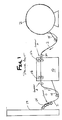
- FIG. 1 a depiction of the prior art process of coil lubrication is shown. More specifically, the coil 2 is directed from the uncoiler and engages a roller interconnected to a dancer arm 34 .
- the dancer arm 34 provides tension to the coil 2 thereby ensuring that the coil 2 correctly contacts rollers 38 and does not become too slack or too tight.
- the coil 2 is driven by a plurality of steel drive rollers 42 of an emulsion lubricator 46 .
- “Emulsion lubricator” 46 generally refers to a device that applies lubricant, such as an oil/water mixture onto at least one surface of the coil 2 .
- the coil 2 is then directed adjacent to a pair of rubber metering rollers 50 that alter the thickness of the applied lubrication. More specifically, depending on the forming process occurring downstream in the assembly line, the amount and thickness of lubricant applied to the coil 2 will vary.
- the rubber metering rolls 50 thus provide a mechanism to control the amount of lubricant being applied to the coil. If, for example, the coil 2 is to be vigorously formed or stamped the amount of lubrication required will be greater than if only simple metal manipulation is required. The selection of lubricant thickness is well known to those skilled in the art.
- the coil 2 exits the emulsion lubricator 46 it is directed to another dancer arm 34 that maintains the tension of the coil 2 . Thereafter, the coil 2 is directed via a catenary 54 to a blank and draw machine 58 or other forming device.
- Various embodiments of the present invention may be located prior to the emulsion lubricator 46 (location A), after the emulsion lubricator 46 (location B), or prior to entry into the blank and draw machine 58 (location C).
- Embodiments of the present invention have been tested at location B wherein no actual lubrication is applied by the emulsion lubricator 46 .
- the emulsion lubricator 46 in the experiments was used to provide a drive mechanism that directs the coil to the lubricating mechanism of embodiments of the present invention, thereby illustrating how embodiments of the present invention can be easily integrated into existing processes.
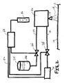
- a control unit 62 is employed that selectively operates an oil valve 66 and an air valve 70 .
- the oil valve 66 supplies lubricant 30 from a reservoir 74 to the oil line 22 that feeds the injector 26 .
- the air valve 70 provides compressed air from an air supply 78 via an air line 18 to the injector 26 .
- the air supply 78 is controlled via an air compressor control line 82 that is interconnected to the control unit 62 that directs the air supply to engage and disengage.
- lubricant 30 via the oil line 22 , and air, via the air line 18 , are directed into the injector 26 and then through the nozzle 14 which generates a spray 10 that coats the coil 2 with a predetermined amount of lubricant 30 .
- a proximity switch 86 may be employed in one embodiment.
- the proximity switch 86 simply lets the control unit 62 ascertain the speed of which the coil 2 is being directed into the non-contact lubricator 90 .
- the amount of spray 10 being injected from the nozzle 14 depends on the intake speed of the coil 2 . The slower the coil 2 is moving, a reduced flow rate of spray 10 is injected out of the nozzle 14 , thereby ensuring that the thickness of the lubricant 30 applied to the coil 2 does not exceed a predetermined level. If the coil 2 is moving too slow, i.e. a “tight roll condition, the uncoiler may be shut down.
- the control unit 62 will direct additional lubricant 30 and air into the injector 26 to ensure that the layer of lubricant 30 is not below a predetermined level.
- the proximity switch 86 will speed up the movement of the coil 2 and spray 10 from the nozzle 14 if the coil 2 becomes too slack wherein it may contact the floor and damage or contaminate the coil 2 .
- the injector 26 may be operated at a constant flow rate, and the thickness of lubricant 30 applied to the coil 2 controlled specifically by the speed of the coil 2 .
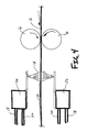
- the coil 2 is directed from an uncoiler 90 in a generally arcuate path into the non-contact spray lubricator 94 .
- the non-contact spray lubricator 94 includes a plurality of guide rollers 6 , preferably positioned above and below the coil 2 that direct the coil 2 from the uncoiler 90 into the non-contact spray lubricator 94 .
- a plurality of proximity sensors are provided, that are comprised of a transmitter 98 and a receiver 102 .
- a signal 106 is sent, for example, from a low speed transmitter 98 A to a low speed receiver 102 A.
- the control unit of the non-contact spray lubricator 94 assesses that the coil 2 has not dipped too close to the ground. Once the low speed signal 106 is broken, the control unit will increase the coil speed or increase the amount of lubricant 30 deposited on the coil 2 .
- a high speed transmitter 98 B and receiver 102 B are not in line of sight, such that any signal sent from the high speed transmitter 98 B is reflected by the coil 2 . This condition indicates that the system is running properly and at the correct coil speed. If the high speed receiver 102 B is receiving a signal from the high speed transmitter 98 B the uncoiler is sending coil at a decreased rate. When a tight coil transmitter 98 C successfully sends a signal to a tight coil receiver 102 C, the tight coil is apparent wherein the uncoiler and lubricator are shut down.
- the proximity sensors may not be required wherein other methods known in the art were used to control the amount of lubrication applied to the coil.
- the uncoiler may feed coil directly to the non-contact spray lubricator in a non-accurate manner.
- the non-contact lubricator may include a mechanism that pulls the coil directly from the uncoiler in a generally straight path.
- FIGS. 1-4 a process of using one embodiment of the present invention is described.
- a traditional drawing and blanking process as shown in FIG. 1 is employed, or alternatively an uncoiler 90 may be spaced a predetermined distance from the non-contact lubricator 94 .
- the non-contact spray lubrication process is then initiated, wherein the coil 2 is directed beneath and above nozzles 14 that are interconnected to a plurality of air/oil fed injectors 26 .
- the proximity sensors are also activated wherein the signal 106 is received by the low speed receiver 102 A from the low speed transmitter 98 A.
- the signals from the high speed transmitter 98 B and a tight coil transmitter 98 C are blocked from their respective receivers initially.
- the proximity sensors are continuously monitored thereby dictating the speed of the uncoiler and/or the flow rate of the nozzles 14 .
- the system preferably shuts down.
- any number of control mechanisms may be implemented to feed the coil 2 into the non-contact spray lubricator 94 . More specifically, it may be unnecessary to utilize a loop configuration as shown in FIG. 3 , and wherein the coil 2 may be fed directly into the non-contact spray lubricator 94 .
Landscapes
- Engineering & Computer Science (AREA)
- Mechanical Engineering (AREA)
- Application Of Or Painting With Fluid Materials (AREA)
- Mounting, Exchange, And Manufacturing Of Dies (AREA)
- Presses And Accessory Devices Thereof (AREA)
Abstract
A non-contact spray lubrication device is provided that applies a thin layer of lubrication to a sheet of metal emanating from a coil. The amount of lubrication is important for metal forming and thus the speed of which the coil is being placed near nozzles of the non-contact spray lubricator is monitored by a plurality of proximity sensors that dictate the amount of spray being dispensed out of a nozzle and/or the speed of the coil.
Description
- This application claims the benefit of U.S. Patent Application Ser. No. 60/827,897, filed Oct. 3, 2006, the entire disclosure of which is incorporated by reference herein.
- The present invention is related generally to sheet metal lubrication. More specifically, an apparatus and method is provided that monitors and regulates the intake speed of a sheet metal coil and applies a predetermined thickness of lubricant thereto.
- A drawn and ironed container generally comprises two pieces, i.e., the container body and the container end closure. In order to form the container body, a portion of aluminum or metallic sheet from a coil is formed to a predetermined shape. Each coil typically weighs about 15,000 to 25,000 pounds and when rolled out flat can be anywhere from 20,000 ft. to 30,000 ft. long and 6 ft. wide. The sheet metal coil is positioned in an uncoiler machine at the beginning of the beverage can assembly. The uncoiler provides the function of unrolling the metal sheet that is fed into a lubricator prior to the forming operation. The lubricator deposits a thin film of lubricant on both sides of the metal sheet that allows the metal to flow smoothly during the subsequent forming processes. The forming process of a drawn and ironed container begins in a large machine called a cupping press that cuts circular disks from the sheet and forms them into cups that drop from the press onto a conveyor for further forming. These two metal forming operations are generally called blank and draw, respectively, and are performed at speeds ranging from 1,500 to 3,000 cups per minute.
- It is important to ensure that the proper amount of lubrication is applied to the raw sheet coming from the coil. That is, metal lubrication has been referred to as an art as well as a science, wherein subtle differences in forming processes and workpiece metallurgy can greatly affect the performance of lubrication. For example, having the incorrect amount or type of lubrication can adversely affect the metal forming process causing tool seizure, excess heat generation, tool wear, etc. The importance of correct lubrication of the metallic sheet prior to metal forming during the cupper operation is thus critical to an efficient container manufacturing operation.
- Traditional lubricating machines employ rollers to apply the lubrication on the metallic sheet. The prior art has many drawbacks, such as inconsistent lubrication weights, i.e. thicknesses of lubrication on the metal, and an increase in moving parts. As appreciated by one skilled in the art, all of these drawbacks can result in equipment failure, increased maintenance and downtime in the manufacturing process which results in additional costs.
- Thus it is a long felt need in the field of beverage container manufacturing to provide a lubrication system that reduces moving parts while providing a method of applying a predetermined metered amount of lubrication on the coil of sheet metal. The following disclosure describes an improved lubrication system that utilizes a non-contact spraying mechanism and that monitors and controls the speed at which the coil is fed into the lubrication machine, thus ensuring that the correct amount and thickness of lubricant is deposited on the metallic sheet prior to the cupper operation.
- It is thus one aspect of the present invention to provide a non-contact spray lubrication system for use in drawn and ironed container manufacturing. More specifically, one embodiment of the present invention includes a plurality of guide rollers that direct a dry coil of metal, preferably aluminum or steel, adjacent to nozzles positioned above and below the coil. The nozzles receive lubricant and air from a reservoir and an air supply via a compressed air source. The nozzles apply a predetermined thickness of lubricant on the metallic coil surface, thereby preparing it for further forming operations.
- It is another aspect of the present invention to provide a method for monitoring and controlling the speed of the coil being fed into the non-contact spray lubricator. More specifically, various embodiments of the present invention employ a plurality of proximity sensors positioned at various locations adjacent to the coil as it follows its path from an uncoiler machine to the non-contact spray lubricator. Generally, the coil follows a downward sloping arcuate path that begins at the uncoiler and ends at the non-contact spray lubricator. The proximity sensors generally include a signal transmitter and a signal receiver wherein depending on the radius of curvature of the coil between the uncoiler, signals emitted by the transmitters will be received by their respective receivers. For example, when all receivers are not receiving a signal the uncoiler will decrease in speed thereby ensuring that the coil does not touch the ground. In addition, it is contemplated that the amount of lubrication being injected from the nozzles and related thickness of lubricant on the metal sheet may be selectively altered depending on the speed that the coil is entering the lubricator. Although optical proximity sensors are described as being used in one embodiment of the present invention, one skilled in the art will appreciate that other types of proximity sensors may be utilized to monitor the coil path and/or speed of travel of the coil without departing from the scope of the invention.
- As appreciated by one skilled in the art, the present invention has many advantages including reduced maintenance due to a reduction in moving parts, more consistent lubrication thickness and reduced maintenance since rollers do not need to be replaced, cleaned, etc. Other advantages will be apparent to those skilled in the art upon review of the following.
- The Summary of the Invention is neither intended nor should it be construed as being representative of the full extent and scope of the present invention. The present invention is set forth in various levels of detail in the Summary of the Invention as well as in the attached drawings and the Detailed Description of the Invention and no limitation as to the scope of the present invention is intended by either the inclusion or non-inclusion of elements, components, etc. in this Summary of the Invention. Additional aspects of the present invention will become more readily apparent from the Detail Description, particularly when taken together with the drawings.
- The accompanying drawings, which are incorporated in and constitute a part of the specification, illustrate embodiments of the invention and together with the general description of the invention given above and the detailed description of the drawings given below, serve to explain the principles of these inventions.
-
FIG. 1 is a layout of machines employed in blank and draw operations; -
FIG. 2 is a schematic of one embodiment of the present invention; -
FIG. 3 is a front elevation view of one embodiment of the present invention; and -
FIG. 4 is a detailed view ofFIG. 3 . - To assist in the understanding of the present invention the following list of components and associated numbering found in the drawings is provided herein:
-
-
- 2 Coil
- 6 Guide roll
- 10 oil spray
- 14 Nozzle
- 18 Air line
- 22 Oil line
- 26 Injector
- 30 Lubricant
- 34 Dancer arm
- 38 Roller
- 42 Drive rollers
- 46 Emulsion lubricator
- 50 Metering roller
- 54 Catenary
- 58 Blank & draw machine
- 62 Control unit
- 66 Oil valve
- 70 Air valve
- 74 Reservoir
- 78 Air supply
- 82 Air pressure control line
- 86 Proximity switch
- 90 Un-coiler
- 94 Non-contact spray lubricator
- 98A Low speed coil proximity switch transmitter
- 98B High speed coil proximity switch transmitter
- 98C Tight coil proximity switch transmitter
- 102A Low speed coil proximity switch receiver
- 102B High speed coil proximity switch receiver
- 102C Tight coil proximity switch receiver
- 106 Signal
- It should be understood that the drawings are not necessarily to scale. In certain instances, details that are not necessary for an understanding of the invention or that render other details difficult to perceive may have been omitted. It should be further understood that the invention is not necessarily limited to the particular embodiments illustrated herein.
- Referring now to
FIGS. 1-4 , embodiments of the present invention that apply lubricant to a section of sheet metal from acoil loop 2 as provided herein. More specifically, the present invention generally relates to applying lubricant to one or more surfaces of themetallic coil 2 that is to be blanked and drawn in a cupping/forming operation. One embodiment of the present invention employs a plurality of guide rollers 6 that direct thecoil 2 adjacent to anoil spray 10 emanating from one ormore nozzles 14. Theoil spray 10 is driven by anair line 18 and anoil supply line 22 that feed aninjector 26 that is interconnected to thenozzle 14. As a predetermined amount of lubricant 30 is applied to thecoil 2, themetallic coil 2 is subsequently conveyed down the assembly line to be cut and drawn into cups. As referred to herein, the term “coil” 2 generally refers to a sheet of metal such as aluminum or steel emanating from a cylindrical coil of thin sheet stock. - Referring now to
FIG. 1 , a depiction of the prior art process of coil lubrication is shown. More specifically, thecoil 2 is directed from the uncoiler and engages a roller interconnected to adancer arm 34. Thedancer arm 34 provides tension to thecoil 2 thereby ensuring that thecoil 2 correctlycontacts rollers 38 and does not become too slack or too tight. Next, thecoil 2 is driven by a plurality ofsteel drive rollers 42 of anemulsion lubricator 46. “Emulsion lubricator” 46 generally refers to a device that applies lubricant, such as an oil/water mixture onto at least one surface of thecoil 2. Thecoil 2 is then directed adjacent to a pair of rubber metering rollers 50 that alter the thickness of the applied lubrication. More specifically, depending on the forming process occurring downstream in the assembly line, the amount and thickness of lubricant applied to thecoil 2 will vary. The rubber metering rolls 50 thus provide a mechanism to control the amount of lubricant being applied to the coil. If, for example, thecoil 2 is to be vigorously formed or stamped the amount of lubrication required will be greater than if only simple metal manipulation is required. The selection of lubricant thickness is well known to those skilled in the art. After thecoil 2 exits theemulsion lubricator 46 it is directed to anotherdancer arm 34 that maintains the tension of thecoil 2. Thereafter, thecoil 2 is directed via acatenary 54 to a blank anddraw machine 58 or other forming device. - Various embodiments of the present invention that have been briefly described above and that will be described in detail below, may be located prior to the emulsion lubricator 46 (location A), after the emulsion lubricator 46 (location B), or prior to entry into the blank and draw machine 58 (location C). Embodiments of the present invention have been tested at location B wherein no actual lubrication is applied by the
emulsion lubricator 46. Theemulsion lubricator 46 in the experiments was used to provide a drive mechanism that directs the coil to the lubricating mechanism of embodiments of the present invention, thereby illustrating how embodiments of the present invention can be easily integrated into existing processes. - Referring now to
FIG. 2 , a schematic of one embodiment of the present invention is shown. More specifically, acontrol unit 62 is employed that selectively operates anoil valve 66 and anair valve 70. Theoil valve 66 supplies lubricant 30 from areservoir 74 to theoil line 22 that feeds theinjector 26. Similarly, theair valve 70 provides compressed air from anair supply 78 via anair line 18 to theinjector 26. Theair supply 78 is controlled via an aircompressor control line 82 that is interconnected to thecontrol unit 62 that directs the air supply to engage and disengage. During normal operations lubricant 30, via theoil line 22, and air, via theair line 18, are directed into theinjector 26 and then through thenozzle 14 which generates aspray 10 that coats thecoil 2 with a predetermined amount of lubricant 30. - In order to control the amount of lubricant 30 and/or air being directed into the
injector 26, aproximity switch 86 may be employed in one embodiment. Theproximity switch 86 simply lets thecontrol unit 62 ascertain the speed of which thecoil 2 is being directed into thenon-contact lubricator 90. The amount ofspray 10 being injected from thenozzle 14 depends on the intake speed of thecoil 2. The slower thecoil 2 is moving, a reduced flow rate ofspray 10 is injected out of thenozzle 14, thereby ensuring that the thickness of the lubricant 30 applied to thecoil 2 does not exceed a predetermined level. If thecoil 2 is moving too slow, i.e. a “tight roll condition, the uncoiler may be shut down. In addition, if thecoil 2 is moving at a high rate, thecontrol unit 62 will direct additional lubricant 30 and air into theinjector 26 to ensure that the layer of lubricant 30 is not below a predetermined level. Finally, theproximity switch 86 will speed up the movement of thecoil 2 andspray 10 from thenozzle 14 if thecoil 2 becomes too slack wherein it may contact the floor and damage or contaminate thecoil 2. Alternatively, theinjector 26 may be operated at a constant flow rate, and the thickness of lubricant 30 applied to thecoil 2 controlled specifically by the speed of thecoil 2. - Referring now to
FIGS. 3 and 4 , one embodiment of the present invention is shown. As depicted, thecoil 2 is directed from anuncoiler 90 in a generally arcuate path into thenon-contact spray lubricator 94. Thenon-contact spray lubricator 94 includes a plurality of guide rollers 6, preferably positioned above and below thecoil 2 that direct thecoil 2 from theuncoiler 90 into thenon-contact spray lubricator 94. A plurality of proximity sensors are provided, that are comprised of atransmitter 98 and areceiver 102. In the illustrated embodiment, asignal 106 is sent, for example, from alow speed transmitter 98A to a low speed receiver 102A. As long as thesignal 106 is received by the low speed receiver 102A, the control unit of thenon-contact spray lubricator 94 assesses that thecoil 2 has not dipped too close to the ground. Once thelow speed signal 106 is broken, the control unit will increase the coil speed or increase the amount of lubricant 30 deposited on thecoil 2. During normal operations, a high speed transmitter 98B and receiver 102B are not in line of sight, such that any signal sent from the high speed transmitter 98B is reflected by thecoil 2. This condition indicates that the system is running properly and at the correct coil speed. If the high speed receiver 102B is receiving a signal from the high speed transmitter 98B the uncoiler is sending coil at a decreased rate. When a tight coil transmitter 98C successfully sends a signal to a tight coil receiver 102C, the tight coil is apparent wherein the uncoiler and lubricator are shut down. - One skilled in the art will appreciate that the proximity sensors may not be required wherein other methods known in the art were used to control the amount of lubrication applied to the coil. For example, the uncoiler may feed coil directly to the non-contact spray lubricator in a non-accurate manner. Alternatively, the non-contact lubricator may include a mechanism that pulls the coil directly from the uncoiler in a generally straight path.
- Referring again to
FIGS. 1-4 , a process of using one embodiment of the present invention is described. In operation, a traditional drawing and blanking process, as shown inFIG. 1 is employed, or alternatively anuncoiler 90 may be spaced a predetermined distance from thenon-contact lubricator 94. Once thecoil 2 is successfully integrated into theuncoiler 90 and thecoil 2 is placed between the guide rollers 6, the non-contact spray lubrication process is then initiated, wherein thecoil 2 is directed beneath and abovenozzles 14 that are interconnected to a plurality of air/oil fedinjectors 26. When thenon-contact spray lubricator 94 is initiated, the proximity sensors are also activated wherein thesignal 106 is received by the low speed receiver 102A from thelow speed transmitter 98A. The signals from the high speed transmitter 98B and a tight coil transmitter 98C are blocked from their respective receivers initially. As lubrication of the coil continues, variations in the coil path between the uncoiler 90 and thenon-contact spray lubricator 94 will necessarily occur. Thus, the proximity sensors are continuously monitored thereby dictating the speed of the uncoiler and/or the flow rate of thenozzles 14. In a situation where the tight roll receiver 102C is receiving an adverse signal from the tight roll transmitter 98C, the system preferably shuts down. As further appreciated by one skilled in the art, it is feasible that any number of control mechanisms may be implemented to feed thecoil 2 into thenon-contact spray lubricator 94. More specifically, it may be unnecessary to utilize a loop configuration as shown inFIG. 3 , and wherein thecoil 2 may be fed directly into thenon-contact spray lubricator 94. - While various embodiments of the present invention have been described in detail, it is apparent that modifications and alterations of those embodiments will occur to those skilled in the art. However, it is to be expressly understood that such modifications and alterations are within the scope and spirit of the present invention, as set forth in the following claims.
Claims (15)
1. An apparatus for applying a lubricant to a metallic material received from an uncoiling mechanism, comprising:
a reservoir for holding the lubricant;
an air supply;
an injector in communication with said reservoir and said air supply;
a nozzle interconnected to said injector;
a control unit in operable communication with a valve that controls the flow of lubricant from said reservoir to said nozzle;
a first proximity switch comprised of a first transmitter and a first receiver, said first proximity switch interconnected to said control unit;
a second proximity switch comprised of a second transmitter and a second receiver, said second proximity switch interconnected to said control unit;
a third proximity switch comprised of a third transmitter and a third receiver, said third proximity switch interconnected to said control unit; and
wherein the coil travels from the uncoiling mechanism to said apparatus for applying lubrication, such that the receipt of a signal by at least one of said first receiver, said second receiver and said third receiver from at least one of said first transmitter, said second transmitter and said third transmitter, respectively, represents the position of the coil that allows said controller to dictate at least one of the speed in which the coil is positioned approximate to said nozzle and the flow rate of the lubricant, wherein the thickness of the lubricant applied to the metallic material is selectively altered.
2. The apparatus of claim 1 , wherein said nozzle is positioned above the coil and further comprising a second nozzle positioned beneath the metallic material.
3. The apparatus of claim 1 , wherein air from said air supply is selectively directed to said injector with a valve.
4. The apparatus of claim 1 , wherein the lubricant is selectively directed to said injector with a valve.
5. The apparatus of claim 1 , further comprising an un-coiler that is adapted to receive the coil, the un-coiler being spaced from a lubricator device, which includes said nozzle, wherein said first transmitter, said second transmitter and said third transmitter are associated with said un-coiler and said first receiver, said second receiver, and said third receiver are associated with said lubricator device to regulate the speed by which the metallic material travels from the un-coiler.
6. An apparatus for applying a lubricant to a metallic material which is positioned on an uncoiling mechanism, comprising:
a non-contact spray lubrication device that includes a lubricant reservoir, an air supply, a means for injecting associated with said lubricant reservoir and air supply, a means for dispersing associated with said means for injecting and a means for controlling the flow of lubricant from said lubricant reservoir to said means for dispersing;
an un-coiler device that dispenses the metallic material at a predetermined distance from said non-contact spray lubrication device, wherein the metallic material dispersed from the coil is adapted to be positioned proximate to said non-contact spray lubrication device;
at least one transmitter associated with at least one of said non-contact spray lubrication device and said un-coiler device; and
at least one receiver associated with at least one of said non-contact spray lubrication device and said un-coiler device, wherein the thickness of the lubricant applied to the metallic material can be selectively regulated.
7. The apparatus of claim 6 , wherein said means for injecting mixes air from said air supply and the lubricant from said lubrication reservoir and directs said mixture to said means for dispersing.
8. The apparatus of claim 6 , wherein said means for dispersing is at least one of a nozzle, a spout, a discharge pipe, and a discharge aperture.
9. The apparatus of claim 6 wherein said at least one transmitter is comprised of a first transmitter, a second transmitter and a third transmitter and said at least one receiver is a first receiver, a second receiver, and a third receiver; and
wherein when the metallic material travels from the uncoiling mechanism to said non-contact spray lubrication device, such that the receipt of a signal by at least one of said first receiver, said second receiver and said third receiver from at least one of said first transmitter, said second transmitter and said third transmitter, respectively, represents the position of the metallic material between said non-contact spray lubrication device and said uncoiler device that allows said means for controlling to dictate at least one of the speed in which the metallic material is positioned approximate to said means for dispersing and the flow rate of the lubricant is selectively altered.
10. The apparatus of claim 6 , wherein said means for dispersing is positioned above the metallic material and further comprising a second means for dispersing positioned beneath the metallic material.
11. The apparatus of claim 6 , wherein air from said air supply is selectively directed to said means for injecting with a valve.
12. The apparatus of claim 6 , wherein the lubricant is selectively directed to said means for injecting with a valve.
13. A method of continuously applying a film of lubricant to a surface of metallic material stored on a coil, comprising:
providing an uncoiling mechanism for rotatably unwinding a coil of rolled metal material to be formed;
providing a lubricating mechanism with a nozzle for depositing lubricant at a predetermined flow rate on said metallic material;
providing a first proximity switch comprised of a transmitter and a receiver, said first proximity switch positioned a first distance from the ground;
providing a second proximity switch comprised of a transmitter and a receiver, said second proximity switch positioned a second distance from the ground;
providing a third proximity switch comprised of a transmitter and a receiver, said third proximity switch positioned a third distance from the ground;
providing a control unit in communication with said first proximity switch, said second proximity switch and said third proximity switch;
feeding said metallic material from said uncoiling mechanism to said lubricating mechanism in an arcuate path having a first radius of curvature wherein the lowest portion of the coil is located between said second distance and said third distance thereby defining a high speed coil feed condition wherein said coil is positioned under said nozzle at a predetermined speed and said nozzle deposits lubricant at a predetermined flow rate;
increasing with said control unit said flow rate if said first radius of curvature is increased such that said lowest portion of the coil is located between said first distance and said second distance thereby defining a tight roll condition;
at least reducing or terminating said flow rate with said control unit if said first radius of curvature is reduced such that said lowest portion of the coil is located between said third distance and the ground thereby defining a low speed condition.
14. The method of claim 13 , further comprising a second nozzle positioned beneath the metallic material that deposits the lubricant at a predetermined flow rate.
15. The apparatus of claim 13 , wherein said nozzle is interconnected to an injector that receives air from an air supply and lubricant from a lubricant supply.
Priority Applications (1)
| Application Number | Priority Date | Filing Date | Title |
|---|---|---|---|
| US11/866,236 US20080098783A1 (en) | 2006-10-03 | 2007-10-02 | Non-Contact Spray Lubricator |
Applications Claiming Priority (2)
| Application Number | Priority Date | Filing Date | Title |
|---|---|---|---|
| US82789706P | 2006-10-03 | 2006-10-03 | |
| US11/866,236 US20080098783A1 (en) | 2006-10-03 | 2007-10-02 | Non-Contact Spray Lubricator |
Publications (1)
| Publication Number | Publication Date |
|---|---|
| US20080098783A1 true US20080098783A1 (en) | 2008-05-01 |
Family
ID=39328529
Family Applications (1)
| Application Number | Title | Priority Date | Filing Date |
|---|---|---|---|
| US11/866,236 Abandoned US20080098783A1 (en) | 2006-10-03 | 2007-10-02 | Non-Contact Spray Lubricator |
Country Status (1)
| Country | Link |
|---|---|
| US (1) | US20080098783A1 (en) |
Citations (3)
| Publication number | Priority date | Publication date | Assignee | Title |
|---|---|---|---|---|
| US3177749A (en) * | 1960-05-27 | 1965-04-13 | Westinghouse Electric Corp | Control for feeding, measuring, and cutting strip material |
| US4953808A (en) * | 1988-08-08 | 1990-09-04 | Perfecto Industries, Inc. | Apparatus for supplying a sheet metal strip to a press |
| US6491756B1 (en) * | 1999-04-14 | 2002-12-10 | Klaschka Gmbh & Co. | Method and device for spraying workpieces |
-
2007
- 2007-10-02 US US11/866,236 patent/US20080098783A1/en not_active Abandoned
Patent Citations (3)
| Publication number | Priority date | Publication date | Assignee | Title |
|---|---|---|---|---|
| US3177749A (en) * | 1960-05-27 | 1965-04-13 | Westinghouse Electric Corp | Control for feeding, measuring, and cutting strip material |
| US4953808A (en) * | 1988-08-08 | 1990-09-04 | Perfecto Industries, Inc. | Apparatus for supplying a sheet metal strip to a press |
| US6491756B1 (en) * | 1999-04-14 | 2002-12-10 | Klaschka Gmbh & Co. | Method and device for spraying workpieces |
Similar Documents
| Publication | Publication Date | Title |
|---|---|---|
| JP4980504B2 (en) | Lubricating oil supply facility and lubricating oil supplying method | |
| US9433986B2 (en) | Rolling mill roll-cleaning device and cleaning method | |
| US6688434B2 (en) | Conveyor and lubricating apparatus, lubricant dispensing device, and method for applying lubricant to conveyor | |
| US4064970A (en) | Conveyor lubricating apparatus | |
| US6821345B2 (en) | Roller coater apparatus | |
| KR20200135177A (en) | Wire electric discharge machining method and wire electric discharge machine | |
| US8096159B2 (en) | Apparatus and method for supplying lubricant in endless hot rolling equipment | |
| US20080098783A1 (en) | Non-Contact Spray Lubricator | |
| EP0726031A1 (en) | Cigarette rod manufacturing apparatus | |
| US4911267A (en) | Oiler with drippage preventing device | |
| US6713133B2 (en) | Apparatus and method for application of lubricants to the surface of metallic sheet material | |
| US10507503B2 (en) | Apparatus for application and suction-removal of operating fluids in the inlet of cold rolling systems installation | |
| JP2002037068A (en) | Automatic rail oiling device | |
| RU2688833C2 (en) | Method of distribution of glue on tubular cardboard cores in rewinding machines | |
| US2857019A (en) | Apparatus for lubricating blooming mills | |
| WO2003092908A1 (en) | Core oil and fragrance addition apparatus and method | |
| JP2005177594A (en) | Continuous coating method and continuous coating apparatus | |
| JP5630108B2 (en) | Curl molding apparatus and curl molding method | |
| CN208627674U (en) | Strip pickling oiling station | |
| JP5387111B2 (en) | Lubricating rolling method and lubricating apparatus for section steel | |
| US3552354A (en) | Yarn treating apparatus | |
| US20140106073A1 (en) | Method and device for oiling strip material | |
| CN205327080U (en) | Electrodynamic type curved steel rail emollient coating car | |
| CN220574353U (en) | A cooling and cleaning device and a tension and straightening machine | |
| KR20230146288A (en) | Apparatus and system for cutting strip |
Legal Events
| Date | Code | Title | Description |
|---|---|---|---|
| AS | Assignment |
Owner name: BALL CORPORATION, COLORADO Free format text: ASSIGNMENT OF ASSIGNORS INTEREST;ASSIGNOR:GILLEST, KEVIN;REEL/FRAME:020386/0752 Effective date: 20071218 |
|
| STCB | Information on status: application discontinuation |
Free format text: ABANDONED -- FAILURE TO RESPOND TO AN OFFICE ACTION |