US20080098756A1 - Enhanced dehumidification control with variable condenser reheat - Google Patents
Enhanced dehumidification control with variable condenser reheat Download PDFInfo
- Publication number
- US20080098756A1 US20080098756A1 US11/553,027 US55302706A US2008098756A1 US 20080098756 A1 US20080098756 A1 US 20080098756A1 US 55302706 A US55302706 A US 55302706A US 2008098756 A1 US2008098756 A1 US 2008098756A1
- Authority
- US
- United States
- Prior art keywords
- air
- heat exchanger
- recited
- reheat heat
- control system
- Prior art date
- Legal status (The legal status is an assumption and is not a legal conclusion. Google has not performed a legal analysis and makes no representation as to the accuracy of the status listed.)
- Granted
Links
- 238000007791 dehumidification Methods 0.000 title description 24
- 238000000034 method Methods 0.000 claims abstract description 41
- 238000004378 air conditioning Methods 0.000 claims abstract description 30
- 238000001816 cooling Methods 0.000 claims abstract description 26
- 230000006835 compression Effects 0.000 claims abstract description 25
- 238000007906 compression Methods 0.000 claims abstract description 25
- 239000003507 refrigerant Substances 0.000 claims abstract description 22
- 238000004519 manufacturing process Methods 0.000 claims abstract description 3
- 239000007788 liquid Substances 0.000 claims description 3
- 238000003303 reheating Methods 0.000 claims 3
- 239000012530 fluid Substances 0.000 description 23
- 230000001143 conditioned effect Effects 0.000 description 8
- 238000010586 diagram Methods 0.000 description 4
- XLYOFNOQVPJJNP-UHFFFAOYSA-N water Substances O XLYOFNOQVPJJNP-UHFFFAOYSA-N 0.000 description 2
- 230000004075 alteration Effects 0.000 description 1
- 230000005494 condensation Effects 0.000 description 1
- 238000009833 condensation Methods 0.000 description 1
- 230000003750 conditioning effect Effects 0.000 description 1
- 238000010276 construction Methods 0.000 description 1
- 230000007812 deficiency Effects 0.000 description 1
- 230000000593 degrading effect Effects 0.000 description 1
- 230000000694 effects Effects 0.000 description 1
- 238000010438 heat treatment Methods 0.000 description 1
- 230000007935 neutral effect Effects 0.000 description 1
- 238000009420 retrofitting Methods 0.000 description 1
- 238000006467 substitution reaction Methods 0.000 description 1
- 238000011144 upstream manufacturing Methods 0.000 description 1
Images

Classifications
-
- F—MECHANICAL ENGINEERING; LIGHTING; HEATING; WEAPONS; BLASTING
- F24—HEATING; RANGES; VENTILATING
- F24F—AIR-CONDITIONING; AIR-HUMIDIFICATION; VENTILATION; USE OF AIR CURRENTS FOR SCREENING
- F24F3/00—Air-conditioning systems in which conditioned primary air is supplied from one or more central stations to distributing units in the rooms or spaces where it may receive secondary treatment; Apparatus specially designed for such systems
- F24F3/12—Air-conditioning systems in which conditioned primary air is supplied from one or more central stations to distributing units in the rooms or spaces where it may receive secondary treatment; Apparatus specially designed for such systems characterised by the treatment of the air otherwise than by heating and cooling
- F24F3/14—Air-conditioning systems in which conditioned primary air is supplied from one or more central stations to distributing units in the rooms or spaces where it may receive secondary treatment; Apparatus specially designed for such systems characterised by the treatment of the air otherwise than by heating and cooling by humidification; by dehumidification
- F24F3/153—Air-conditioning systems in which conditioned primary air is supplied from one or more central stations to distributing units in the rooms or spaces where it may receive secondary treatment; Apparatus specially designed for such systems characterised by the treatment of the air otherwise than by heating and cooling by humidification; by dehumidification with subsequent heating, i.e. with the air, given the required humidity in the central station, passing a heating element to achieve the required temperature
-
- F—MECHANICAL ENGINEERING; LIGHTING; HEATING; WEAPONS; BLASTING
- F24—HEATING; RANGES; VENTILATING
- F24F—AIR-CONDITIONING; AIR-HUMIDIFICATION; VENTILATION; USE OF AIR CURRENTS FOR SCREENING
- F24F11/00—Control or safety arrangements
- F24F11/62—Control or safety arrangements characterised by the type of control or by internal processing, e.g. using fuzzy logic, adaptive control or estimation of values
- F24F11/63—Electronic processing
-
- F—MECHANICAL ENGINEERING; LIGHTING; HEATING; WEAPONS; BLASTING
- F24—HEATING; RANGES; VENTILATING
- F24F—AIR-CONDITIONING; AIR-HUMIDIFICATION; VENTILATION; USE OF AIR CURRENTS FOR SCREENING
- F24F11/00—Control or safety arrangements
- F24F11/70—Control systems characterised by their outputs; Constructional details thereof
- F24F11/72—Control systems characterised by their outputs; Constructional details thereof for controlling the supply of treated air, e.g. its pressure
- F24F11/74—Control systems characterised by their outputs; Constructional details thereof for controlling the supply of treated air, e.g. its pressure for controlling air flow rate or air velocity
- F24F11/77—Control systems characterised by their outputs; Constructional details thereof for controlling the supply of treated air, e.g. its pressure for controlling air flow rate or air velocity by controlling the speed of ventilators
-
- F—MECHANICAL ENGINEERING; LIGHTING; HEATING; WEAPONS; BLASTING
- F24—HEATING; RANGES; VENTILATING
- F24F—AIR-CONDITIONING; AIR-HUMIDIFICATION; VENTILATION; USE OF AIR CURRENTS FOR SCREENING
- F24F11/00—Control or safety arrangements
- F24F11/70—Control systems characterised by their outputs; Constructional details thereof
- F24F11/80—Control systems characterised by their outputs; Constructional details thereof for controlling the temperature of the supplied air
- F24F11/81—Control systems characterised by their outputs; Constructional details thereof for controlling the temperature of the supplied air by controlling the air supply to heat-exchangers or bypass channels
-
- F—MECHANICAL ENGINEERING; LIGHTING; HEATING; WEAPONS; BLASTING
- F24—HEATING; RANGES; VENTILATING
- F24F—AIR-CONDITIONING; AIR-HUMIDIFICATION; VENTILATION; USE OF AIR CURRENTS FOR SCREENING
- F24F11/00—Control or safety arrangements
- F24F11/70—Control systems characterised by their outputs; Constructional details thereof
- F24F11/80—Control systems characterised by their outputs; Constructional details thereof for controlling the temperature of the supplied air
- F24F11/83—Control systems characterised by their outputs; Constructional details thereof for controlling the temperature of the supplied air by controlling the supply of heat-exchange fluids to heat-exchangers
- F24F11/84—Control systems characterised by their outputs; Constructional details thereof for controlling the temperature of the supplied air by controlling the supply of heat-exchange fluids to heat-exchangers using valves
-
- F—MECHANICAL ENGINEERING; LIGHTING; HEATING; WEAPONS; BLASTING
- F24—HEATING; RANGES; VENTILATING
- F24F—AIR-CONDITIONING; AIR-HUMIDIFICATION; VENTILATION; USE OF AIR CURRENTS FOR SCREENING
- F24F11/00—Control or safety arrangements
- F24F11/70—Control systems characterised by their outputs; Constructional details thereof
- F24F11/80—Control systems characterised by their outputs; Constructional details thereof for controlling the temperature of the supplied air
- F24F11/86—Control systems characterised by their outputs; Constructional details thereof for controlling the temperature of the supplied air by controlling compressors within refrigeration or heat pump circuits
-
- F—MECHANICAL ENGINEERING; LIGHTING; HEATING; WEAPONS; BLASTING
- F24—HEATING; RANGES; VENTILATING
- F24F—AIR-CONDITIONING; AIR-HUMIDIFICATION; VENTILATION; USE OF AIR CURRENTS FOR SCREENING
- F24F11/00—Control or safety arrangements
- F24F11/30—Control or safety arrangements for purposes related to the operation of the system, e.g. for safety or monitoring
-
- F—MECHANICAL ENGINEERING; LIGHTING; HEATING; WEAPONS; BLASTING
- F24—HEATING; RANGES; VENTILATING
- F24F—AIR-CONDITIONING; AIR-HUMIDIFICATION; VENTILATION; USE OF AIR CURRENTS FOR SCREENING
- F24F2110/00—Control inputs relating to air properties
- F24F2110/10—Temperature
-
- F—MECHANICAL ENGINEERING; LIGHTING; HEATING; WEAPONS; BLASTING
- F24—HEATING; RANGES; VENTILATING
- F24F—AIR-CONDITIONING; AIR-HUMIDIFICATION; VENTILATION; USE OF AIR CURRENTS FOR SCREENING
- F24F2110/00—Control inputs relating to air properties
- F24F2110/20—Humidity
-
- F—MECHANICAL ENGINEERING; LIGHTING; HEATING; WEAPONS; BLASTING
- F24—HEATING; RANGES; VENTILATING
- F24F—AIR-CONDITIONING; AIR-HUMIDIFICATION; VENTILATION; USE OF AIR CURRENTS FOR SCREENING
- F24F2140/00—Control inputs relating to system states
Definitions
- the present invention is directed, in general, to air conditioning and, more particularly, to a control system for air conditioning systems employing dehumidification and re-heat.
- Air conditioning systems with a re-heating system for active humidity control can overcool the air provided to the conditioned space while performing active dehumidification. This occurs because the re-heat coil is not sized to provide neutral supply air temperature.
- condenser re-heat systems like the Lennox Humiditrol® EDA, still have a Sensible cooling-to-Total cooling ratio (S/T) of about 0.25 so that some sensible cooling is occurring while dehumidification is being required by the humidistat setting.
- S/T Sensible cooling-to-Total cooling ratio
- a typical control scheme uses “cooling priority” first to satisfy the cooling requirement from the thermostat, and then, if there is excess humidity detected by the humidity sensor, the vapor compression circuit and evaporator continue to cool the air so that the excess humidity can be removed. Since, under most conditions, there is a positive S/T ratio, the space continues to be cooled during this continued dehumidification mode. This results in overcooling of the air and conditioned space. Some thermostats even employ an “overcooling limit” to stop the dehumidification mode from lowering the conditioned air too far below the temperature setpoint even if the desired relative humidity has not been met. The fact that enhanced dehumidification is only enabled after the temperature setpoint has been achieved means that more than the minimum amount of energy is being used to provide the space with conditioned air.
- an air conditioning system comprising an air mover for circulating air to a space; a vapor compression circuit including a compressor, a condenser, and an expansion device; an evaporator; an air-reheat heat exchanger; and a control system.
- the evaporator receives refrigerant from the vapor compression circuit and is adapted to provide a cooled stream of air to the space.
- the air-reheat heat exchanger is positioned to receive the cooled stream of air.
- the vapor compression circuit, the evaporator, and the air-reheat heat exchanger are operable in combination to provide a plurality of modes of operation.
- control system is configured to compute a Sensible cooling-to-Total cooling (S/T) process ratio and to control an operation of at least one of the vapor compression circuit, the evaporator, and the air-reheat heat exchanger.
- S/T Sensible cooling-to-Total cooling
- a method of manufacturing the air conditioning system is also provided.
- FIG. 1 illustrates a schematic diagram of an air conditioning system constructed according to the principles of the present invention
- FIG. 2 illustrates a flow diagram for an enhanced dehumidification control algorithm assembled in accordance with the principles of the present invention as implemented in the controller of FIG. 1 ;
- FIG. 3 illustrates a performance chart of three modes of operation of the air conditioning system of FIG. 1 with a 75° F. indoor dry bulb temperature and a 66% indoor relative humidity;
- FIG. 4 illustrates a psychrometric chart covering normal indoor temperature and humidity ranges.
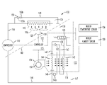
- the air conditioning system 100 comprises a conventional electric motor-driven compressor 110 connected via a conduit 114 to a refrigerant fluid, primary condenser heat exchanger 116 disposed typically outdoors.
- the heat exchange between fluid flowing through the condenser heat exchanger 116 and ambient outside air is controlled by a fan 118 having a plurality of fixed pitch blades 118 a and which is driven by a variable-speed electric motor 120 .
- the variable-speed electric motor 120 may be an electrically-commutated type operating on variable frequency and voltage AC electric power as supplied to the motor 120 via a suitable controller 122 .
- Fan 118 propels a heat exchange medium, such as ambient “outdoor” air through condenser heat exchanger 116 in a known manner.
- Condenser heat exchanger 116 may also operate with other forms of heat exchange medium at controlled flow rates thereof. Control of heat exchange medium flowing over condenser heat exchanger 116 may take other forms such as a constant-speed variable pitch fan, air flow control louvers, or control of a variable flow of a liquid heat exchange medium.
- Condenser heat exchanger 116 is also operably connected to a conventional refrigerant fluid filter and dryer 124 disposed in a conduit 126 for conducting condensed refrigerant fluid to a power-operated or so called motor-controlled valve 128 .
- Valve 128 may be controlled by a solenoid, for example, and may be of a type commercially available.
- the solenoid for the valve 128 is also adapted to be controlled by a suitable humidity sensor 130 through controller 122 disposed in a space 132 to be conditioned by the system 100 .
- the humidity sensor 130 may be a conventional humidistat with capability to receive input of a desired relative humidity called a relative humidity setpoint RH sp .
- the humidity sensor 130 is also operably connected to controller 122 .
- a temperature sensor 134 disposed within the conditioned space 132 , is also operably connected to the controller 122 .
- the temperature sensor 134 may be a conventional thermostat with capability to receive input of a desired temperature called a temperature setpoint T ps .
- Controlled and conditioned space 132 is represented only schematically in the drawing figures and a return air path from space 132 or another source of air to be conditioned is omitted in the interest of conciseness.
- Conduit 126 is connected by way of valve 128 to further refrigerant conducting conduits 136 and 138 to a conventional refrigerant fluid expansion device 140 and to an air-reheat heat exchanger 142 , respectively.
- the compressor 110 , condenser 116 , and expansion device 140 together may be properly termed a vapor compression circuit.
- the vapor compression circuit is sized so as to enable conditioning of the air returned to space 132 at the desired relative humidity RH sp .
- Conduit 136 is operable to deliver refrigerant fluid to a heat exchanger or so called evaporator 144 by way of the expansion device 140 .
- Expansion device 140 is coupled to a remote temperature sensor 140 a which is adapted to sense the temperature of refrigerant fluid leaving the heat exchanger 144 by way of a conduit 146 .
- Conduit 146 is commonly known as the suction line leading to compressor 110 whereby refrigerant fluid in vapor form is compressed and recirculated through the system 100 by way of condenser heat exchanger 116 .
- a suitable valve operator vent conduit 147 is connected between valve 128 and conduit 146 .
- Heat exchangers 116 , 142 and 144 may be conventional multiple fin and tube type devices, for example.
- Air-reheat heat exchanger also known as an air-reheat condenser 142 is adapted to receive refrigerant fluid from condenser heat exchanger 116 through conduit 138 and discharge such fluid through a conduit 143 and a check valve 145 to conduit 136 upstream of expansion device 140 .
- the air-reheat condenser 142 is capable of and may be used to raise the temperature of air returned to space 132 to the desired temperature T sp . Under certain operating conditions refrigerant fluid may also be advantageously permitted to bypass the condenser heat exchanger 116 through a conduit 149 and a pressure relief valve 150 .
- Pressure relief valve 150 includes a closure member 150 a which is biased into a valve-closed position by resilient means, such as a coil spring 150 b .
- the pressure relief valve 150 operates to bypass fluid flowing through conduit 114 around the condenser heat exchanger 116 directly to conduit 126 downstream of the filter/dryer 124 , as shown, and to the air reheat heat exchanger 142 .
- controller 122 operates to control a drive motor 152 for a supply air blower or fan 154 of a conventional type.
- Ambient outdoor air, or air being circulated as return air from space 132 is propelled by motor driven blower 154 through a suitable duct 156 wherein the heat exchangers 142 and 44 are disposed.
- air-reheat heat exchanger 142 is downstream of heat exchanger 144 .
- the system 100 includes elements of a conventional vapor compression air conditioning system wherein compressor 110 compresses a suitable refrigerant fluid which is condensed in condenser heat exchanger 116 and is conducted to heat exchanger or evaporator 144 through expansion device 140 wherein the condensed refrigerant fluid is expanded and absorbs heat from the air flowing through the duct 156 to provide cooled air to space 132 .
- This operation is controlled by controller 122 using data demanded by temperature sensor 134 and humidity sensor 130 .
- Controller 122 operates to control fan motor 152 as well as motor driven compressor 110 and the variable speed fan motor 120 which controls the amount of cooling air flowing over condenser heat exchanger 116 .
- Controller 122 comprises a microprocessor 125 for management of an algorithm to be described below.
- control valve 128 will be actuated to force refrigerant fluid to and through air-reheat heat exchanger 142 giving up heat to air flowing through the duct 156 into the space 132 thereby raising the temperature of such air and reducing the rate of sensible cooling occurring.
- Blower 154 may also be termed an air mover. Accordingly, air propelled by blower 154 is first cooled by heat exchanger 144 to condense moisture therein and is then reheated by air-reheat heat exchanger 142 to meet the temperature and humidity requirements of the space 132 .
- the controller 122 reduces the speed of the fan motor 120 and fan 118 , thereby reducing the heat exchange taking place by air flow through the condenser heat exchanger 116 .
- Fan motor 120 may be controlled to continuously vary the speed of fan 118 or motor output speed may be varied in discrete steps. In this way a greater heat rejection load is placed on air-reheat heat exchanger 142 , progressively, thus raising the temperature of the air flowing into space 132 to further reduce the relative humidity.
- the blower 154 is also reduced in speed during enhanced dehumidification operation.
- the configuration of the condenser heat exchanger 116 may be such as to impose a relatively large fluid pressure drop thereacross for refrigerant fluid flowing therethrough, particularly if a substantial amount of such fluid is remaining in gaseous form.
- refrigerant fluid in gaseous form may bypass heat exchanger 116 by way of pressure relief valve 150 and conduit 149 without degrading the performance of the system 100 .
- the outdoor portion of system 100 typically includes the compressor 110 and the condenser heat exchanger 116 , as well as the condenser fan and motor 118 , 120 .
- only conduits 126 and 146 and control wiring for compressor 110 and motor 120 are required to extend between the indoor and outdoor parts of the system as diagrammatically separated by dashed line 160 .
- This improved arrangement provides for retrofitting of certain air conditioning systems, since the outdoor portion of an existing system may be unaffected by replacing the original indoor portion of the existing system with the indoor portion of system 100 .
- Relative humidity setpoint RH sp and temperature setpoint T sp have been previously described as the commanded relative humidity and temperature for the space 132 .
- the humidistat 130 senses and reports to the controller 122 the current relative humidity RH id of the space 132 .
- the thermostat 134 senses and reports to the controller 122 the current indoor temperature T id of the space 132 .
- the absolute humidity ratio for the setpoint ⁇ sp conditions is defined as the pounds of water (H 2 0) per pound of air for the relative humidity setpoint RH sp and temperature setpoint T sp conditions.
- the absolute indoor humidity ratio ⁇ id is defined as the pounds of water per pound of air.
- ⁇ id [ ( RH id 0.4 ) * ( 7.875 + 0.00010438 * T id 3 ) + ( 0.0005 * ( Tid - 50 ) 2.2 ) ] * [ 1 7000 ] Eq . ⁇ 2
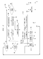
- Step 205 the microprocessor 125 within the controller 122 determines if the humidistat 130 is calling for dehumidification. If the answer is NO, then the algorithm proceeds to Step 210 wherein the microprocessor 125 determines if the thermostat 134 is calling for cooling. If the answer is NO, then the algorithm proceeds to Step 215 confirming that both cooling and dehumidification are OFF. The microprocessor 125 then continues to loop 220 and returns to Step 205 wherein the algorithm 200 continues.
- Step 210 if the microprocessor 125 determines that the thermostat 134 is calling for cooling, i.e., the answer is YES, the algorithm 200 proceeds to Step 218 , and normal cooling is commanded by the controller 122 . The microprocessor 125 then continues to loop 220 and returns to Step 205 wherein the algorithm 200 continues.
- This portion of the algorithm 200 as described constitutes a normal cooling cycle as one who is of skill in the art would expect, except that the algorithm 200 is arranged for dehumidification priority as compared to conventional cooling priority.
- Step 205 if the microprocessor 125 determines that the humidistat 130 is calling for dehumidification, i.e., the answer is YES, the algorithm 200 proceeds to Step 230 .
- the microprocessor 125 determines if the thermostat 134 is calling for cooling. If the answer is NO, the algorithm 200 proceeds to Step 235 , and dehumidification at the minimum S/T is commanded by the controller 122 . If the answer is YES, the algorithm 200 proceeds to Step 240 .
- the microprocessor 125 calculates ⁇ sp from the setpoint temperature T sp and setpoint relative humidity RH sp in accordance with Equation 1.
- the algorithm 200 proceeds to Step 245 where ⁇ id is calculated from current indoor temperature T id and current indoor relative humidity RH id in accordance with Equation 2.
- the algorithm 200 then proceeds to Step 250 where latent load L is calculated from ⁇ id and ⁇ sp in accordance with Equation 3.
- sensible load S is calculated in accordance with Equation 4 from T id and T sp .
- the microprocessor 125 there are resident dehumidification modes 1 through n corresponding to n configurations of the various variable elements of the system 100 .
- the variable elements may include, but are not limited to, outdoor fan speed, air-reheat condenser 142 active or inactive, indoor fan speed, etc.
- Associated with each of the dehumidification modes 1 through n is a pre-calculated S/T ratio.
- the microprocessor uses these pre-calculated S/T ratios, i.e., S/T 1 , S/T 2 , . . . S/T n ⁇ 1 , S/T n , for comparison with the Process S/T Ratio.
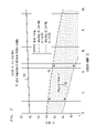
- FIG. 3 illustrated is a performance chart of three modes of operation of the air conditioning system 100 of FIG. 1 with a 75° F. indoor dry bulb temperature and a 66% indoor relative humidity.
- a normal cooling without reheat performance of the system 100 is shown in a first graphical plot 310 .
- a second graphical plot 320 shows a system configuration of dehumidification (air-reheat condenser 142 active) with the outdoor fan operating at 100 percent and the indoor fan operating at 65 percent.
- a third graphical plot 330 shows a configuration of dehumidification (air-reheat condenser 142 active) with the outdoor fan operating at 30 percent and the indoor fan operating at 65 percent.
- the performance of the system 100 will follow the appropriate graph for the selected configuration.
- the S/T ratio for the normal cooling without reheat stays relatively flat at about 0.61 to about 0.63 over the temperature range from about 75° F. to about 104° F.
- the S/T ratio for the second configuration is shown to vary substantially linearly from about 0.4 at 75° F. to about 0.25 at about 95° F.
- the third configuration S/T ratio is shown to vary substantially linearly from about 0.2 at 75° F. to about 0.08 at about 85° F.
- Step 240 calculates ⁇ sp . From Equation 1, with T sp at 75° F. and RH sp at 50% (0.50), ⁇ sp evaluates to 0.0094. At Step 245 with T id at 77° F. and RH id at 49% (0.49), ⁇ id evaluates to 0.0098 from Equation 2.
- latent load L evaluates to 0.487 BTU/lb of air from Equation 3.
- sensible load S evaluates to 0.48 BTU/lb of air from Equation 4.
- the S/T process ratio evaluates to 0.497 from Equation 5.
- the S/T process ratio of 0.497 is compared to the known S/T ratios for the three configurations of the system 100 . Within Step 265 , the S/T process ratio of 0.497 is compared to the S/T Mode 1 ratio of about 0.18.
- the S/T process ratio is greater than the S/T Mode 1 ratio, however, it is not yet known if the S/T process ratio is greater than the S/T Mode 2 ratio.
- the S/T process ratio of 0.497 is found to be greater than the S/T Mode 2 ratio of about 0.38. Again however, it is not yet known if the S/T process ratio is greater than the S/T Mode 3 ratio.
- the S/T process ratio of 0.497 is found to be less than the S/T Mode 3 ratio of about 0.60.
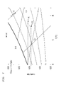
- a psychrometric chart 400 covering normal indoor temperature and humidity ranges.
- Normal indoor temperature ranges from about 68° F. to about 82° F. and is indicated along the abscissa.
- the ordinate covers an absolute humidity ratio ranging from about 0.0 to about 0.020.
- Current temperature and absolute humidity ratio is represented as a first point 410 at 77° F. and about 0.011 humidity ratio.
- the desired temperature, 75° F. and about 0.0093 absolute humidity ratio is represented as a second point 420 .
- the path from the first point 410 to the second point 420 represents the desired process path.
- Operating the system 100 in dehumidification mode 2 with air-reheat condenser 142 active, outdoor fan speed at 100%, and indoor fan speed at 65% will approximate the desired process path.
- an air conditioning system employs computation of a Process Sensible to Total Cooling ratio and the selection of the air conditioning system configuration having a reasonable close approximation to the Process Sensible to Total Cooling ratio.
- other parameters of the air conditioning system may also be included, thereby possibly more closely approaching the desired Process Sensible to Total Cooling ratio.
- the control algorithm has a loop 220 arrangement.
- the status of the Process Sensible to Total Cooling ratio is repeatedly evaluated over time and adjustments in air conditioner operation are made in response to changes in the sensible and latent loads.
Landscapes
- Engineering & Computer Science (AREA)
- Chemical & Material Sciences (AREA)
- Combustion & Propulsion (AREA)
- Mechanical Engineering (AREA)
- General Engineering & Computer Science (AREA)
- Physics & Mathematics (AREA)
- Signal Processing (AREA)
- Fluid Mechanics (AREA)
- Fuzzy Systems (AREA)
- Mathematical Physics (AREA)
- Thermal Sciences (AREA)
- Air Conditioning Control Device (AREA)
Abstract
Description
- The present invention is directed, in general, to air conditioning and, more particularly, to a control system for air conditioning systems employing dehumidification and re-heat.
- Air conditioning systems with a re-heating system for active humidity control can overcool the air provided to the conditioned space while performing active dehumidification. This occurs because the re-heat coil is not sized to provide neutral supply air temperature. For example, condenser re-heat systems, like the Lennox Humiditrol® EDA, still have a Sensible cooling-to-Total cooling ratio (S/T) of about 0.25 so that some sensible cooling is occurring while dehumidification is being required by the humidistat setting.
- A typical control scheme uses “cooling priority” first to satisfy the cooling requirement from the thermostat, and then, if there is excess humidity detected by the humidity sensor, the vapor compression circuit and evaporator continue to cool the air so that the excess humidity can be removed. Since, under most conditions, there is a positive S/T ratio, the space continues to be cooled during this continued dehumidification mode. This results in overcooling of the air and conditioned space. Some thermostats even employ an “overcooling limit” to stop the dehumidification mode from lowering the conditioned air too far below the temperature setpoint even if the desired relative humidity has not been met. The fact that enhanced dehumidification is only enabled after the temperature setpoint has been achieved means that more than the minimum amount of energy is being used to provide the space with conditioned air.
- Accordingly, what is needed in the art is an air conditioning system that avoids the wasted energy of overcooling the air in order to achieve the desired relative humidity.
- To address the above-discussed deficiencies of the prior art, the present invention provides, in one aspect, an air conditioning system comprising an air mover for circulating air to a space; a vapor compression circuit including a compressor, a condenser, and an expansion device; an evaporator; an air-reheat heat exchanger; and a control system. In a preferred embodiment, the evaporator receives refrigerant from the vapor compression circuit and is adapted to provide a cooled stream of air to the space. In a further aspect, the air-reheat heat exchanger is positioned to receive the cooled stream of air. In one embodiment, the vapor compression circuit, the evaporator, and the air-reheat heat exchanger are operable in combination to provide a plurality of modes of operation. In a preferred embodiment, the control system is configured to compute a Sensible cooling-to-Total cooling (S/T) process ratio and to control an operation of at least one of the vapor compression circuit, the evaporator, and the air-reheat heat exchanger. A method of manufacturing the air conditioning system is also provided.
- The foregoing has outlined preferred and alternative features of the present invention so that those skilled in the pertinent art may better understand the detailed description of the invention that follows. Additional features of the invention will be described hereinafter that form the subject of the claims of the invention. Those skilled in the pertinent art should appreciate that they can readily use the disclosed conception and specific embodiment as a basis for designing or modifying other structures for carrying out the same purposes of the present invention. Those skilled in the pertinent art should also realize that such equivalent constructions do not depart from the spirit and scope of the invention.
- For a more complete understanding of the invention, reference is now made to the following descriptions taken in conjunction with the accompanying drawing, in which:
-
FIG. 1 illustrates a schematic diagram of an air conditioning system constructed according to the principles of the present invention; -
FIG. 2 illustrates a flow diagram for an enhanced dehumidification control algorithm assembled in accordance with the principles of the present invention as implemented in the controller ofFIG. 1 ; -
FIG. 3 illustrates a performance chart of three modes of operation of the air conditioning system ofFIG. 1 with a 75° F. indoor dry bulb temperature and a 66% indoor relative humidity; and -
FIG. 4 illustrates a psychrometric chart covering normal indoor temperature and humidity ranges. - Referring initially to
FIG. 1 , illustrated is a schematic diagram of anair conditioning system 100 constructed according to the principles of the present invention. Theair conditioning system 100 comprises a conventional electric motor-drivencompressor 110 connected via aconduit 114 to a refrigerant fluid, primarycondenser heat exchanger 116 disposed typically outdoors. The heat exchange between fluid flowing through thecondenser heat exchanger 116 and ambient outside air is controlled by afan 118 having a plurality offixed pitch blades 118 a and which is driven by a variable-speedelectric motor 120. The variable-speedelectric motor 120 may be an electrically-commutated type operating on variable frequency and voltage AC electric power as supplied to themotor 120 via asuitable controller 122.Fan 118 propels a heat exchange medium, such as ambient “outdoor” air throughcondenser heat exchanger 116 in a known manner.Condenser heat exchanger 116 may also operate with other forms of heat exchange medium at controlled flow rates thereof. Control of heat exchange medium flowing overcondenser heat exchanger 116 may take other forms such as a constant-speed variable pitch fan, air flow control louvers, or control of a variable flow of a liquid heat exchange medium.Condenser heat exchanger 116 is also operably connected to a conventional refrigerant fluid filter anddryer 124 disposed in aconduit 126 for conducting condensed refrigerant fluid to a power-operated or so called motor-controlledvalve 128. Valve 128 may be controlled by a solenoid, for example, and may be of a type commercially available. The solenoid for thevalve 128 is also adapted to be controlled by asuitable humidity sensor 130 throughcontroller 122 disposed in aspace 132 to be conditioned by thesystem 100. In a preferred embodiment, thehumidity sensor 130 may be a conventional humidistat with capability to receive input of a desired relative humidity called a relative humidity setpoint RHsp. Thehumidity sensor 130 is also operably connected tocontroller 122. Atemperature sensor 134, disposed within the conditionedspace 132, is also operably connected to thecontroller 122. In a preferred embodiment, thetemperature sensor 134 may be a conventional thermostat with capability to receive input of a desired temperature called a temperature setpoint Tps. Controlled and conditionedspace 132 is represented only schematically in the drawing figures and a return air path fromspace 132 or another source of air to be conditioned is omitted in the interest of conciseness. - Conduit 126 is connected by way of
valve 128 to furtherrefrigerant conducting conduits 136 and 138 to a conventional refrigerantfluid expansion device 140 and to an air-reheat heat exchanger 142, respectively. Thecompressor 110,condenser 116, andexpansion device 140 together may be properly termed a vapor compression circuit. The vapor compression circuit is sized so as to enable conditioning of the air returned tospace 132 at the desired relative humidity RHsp. Conduit 136 is operable to deliver refrigerant fluid to a heat exchanger or so calledevaporator 144 by way of theexpansion device 140.Expansion device 140 is coupled to aremote temperature sensor 140 a which is adapted to sense the temperature of refrigerant fluid leaving theheat exchanger 144 by way of aconduit 146. Conduit 146 is commonly known as the suction line leading tocompressor 110 whereby refrigerant fluid in vapor form is compressed and recirculated through thesystem 100 by way ofcondenser heat exchanger 116. A suitable valveoperator vent conduit 147 is connected betweenvalve 128 andconduit 146.Heat exchangers - Air-reheat heat exchanger, also known as an air-
reheat condenser 142 is adapted to receive refrigerant fluid fromcondenser heat exchanger 116 throughconduit 138 and discharge such fluid through aconduit 143 and acheck valve 145 to conduit 136 upstream ofexpansion device 140. The air-reheat condenser 142 is capable of and may be used to raise the temperature of air returned tospace 132 to the desired temperature Tsp. Under certain operating conditions refrigerant fluid may also be advantageously permitted to bypass thecondenser heat exchanger 116 through aconduit 149 and apressure relief valve 150.Pressure relief valve 150 includes aclosure member 150 a which is biased into a valve-closed position by resilient means, such as acoil spring 150 b. In response to a predetermined pressure, or range of pressures, acting on theclosure member 150 a, thepressure relief valve 150 operates to bypass fluid flowing throughconduit 114 around thecondenser heat exchanger 116 directly to conduit 126 downstream of the filter/dryer 124, as shown, and to the airreheat heat exchanger 142. - In the operation of the
air conditioning system 100,controller 122 operates to control adrive motor 152 for a supply air blower orfan 154 of a conventional type. Ambient outdoor air, or air being circulated as return air fromspace 132, is propelled by motor drivenblower 154 through asuitable duct 156 wherein theheat exchangers 142 and 44 are disposed. Specifically, air-reheat heat exchanger 142 is downstream ofheat exchanger 144. One who is skilled in the art will recognize that thesystem 100 includes elements of a conventional vapor compression air conditioning system whereincompressor 110 compresses a suitable refrigerant fluid which is condensed incondenser heat exchanger 116 and is conducted to heat exchanger orevaporator 144 throughexpansion device 140 wherein the condensed refrigerant fluid is expanded and absorbs heat from the air flowing through theduct 156 to provide cooled air tospace 132. This operation is controlled bycontroller 122 using data demanded bytemperature sensor 134 andhumidity sensor 130.Controller 122 operates to controlfan motor 152 as well as motor drivencompressor 110 and the variablespeed fan motor 120 which controls the amount of cooling air flowing overcondenser heat exchanger 116.Controller 122 comprises amicroprocessor 125 for management of an algorithm to be described below. - If the relative humidity requirements of the
space 132 are not being met by operation of thesystem 100 wherein all refrigerant fluid is being directed fromconduit 126 directly to conduit 136,control valve 128 will be actuated to force refrigerant fluid to and through air-reheat heat exchanger 142 giving up heat to air flowing through theduct 156 into thespace 132 thereby raising the temperature of such air and reducing the rate of sensible cooling occurring. Since refrigerant fluid condensed and highly subcooled in the air-reheat heat exchanger/condenser 142 then flows viaconduit 143 toexpansion device 140 andevaporator 144, substantial cooling effect is imparted to air being discharged byblower 154 and flowing throughevaporator 144 to thereby condense moisture in the air flowing throughduct 156.Blower 154 may also be termed an air mover. Accordingly, air propelled byblower 154 is first cooled byheat exchanger 144 to condense moisture therein and is then reheated by air-reheat heat exchanger 142 to meet the temperature and humidity requirements of thespace 132. If the humidity requirements ofspace 132 are not being met by the aforementioned operation ofsystem 100, thecontroller 122 reduces the speed of thefan motor 120 andfan 118, thereby reducing the heat exchange taking place by air flow through thecondenser heat exchanger 116.Fan motor 120 may be controlled to continuously vary the speed offan 118 or motor output speed may be varied in discrete steps. In this way a greater heat rejection load is placed on air-reheat heat exchanger 142, progressively, thus raising the temperature of the air flowing intospace 132 to further reduce the relative humidity. Commonly, theblower 154 is also reduced in speed during enhanced dehumidification operation. - In those circumstances where the reduced exchange of heat at the
condenser heat exchanger 116 occurs, the configuration of thecondenser heat exchanger 116 may be such as to impose a relatively large fluid pressure drop thereacross for refrigerant fluid flowing therethrough, particularly if a substantial amount of such fluid is remaining in gaseous form. However, since a greater amount of condensation is occurring in air-reheat heat exchanger 142, as the fluid condensing load is shifted fromheat exchanger 116 to air-reheat heat exchanger 142, refrigerant fluid in gaseous form may bypassheat exchanger 116 by way ofpressure relief valve 150 andconduit 149 without degrading the performance of thesystem 100. - Another advantage of the
system 100 is that only two refrigerant fluid conduits are required to extend between the indoor portion of thesystem 100, as indicated by dashedline 160, wherein the indoor portion is that generally below the line as shown in the figure. The outdoor portion ofsystem 100 typically includes thecompressor 110 and thecondenser heat exchanger 116, as well as the condenser fan andmotor conduits compressor 110 andmotor 120 are required to extend between the indoor and outdoor parts of the system as diagrammatically separated by dashedline 160. This improved arrangement provides for retrofitting of certain air conditioning systems, since the outdoor portion of an existing system may be unaffected by replacing the original indoor portion of the existing system with the indoor portion ofsystem 100. - At this point, it is desirable to define terms to be used later in the description. Relative humidity setpoint RHsp and temperature setpoint Tsp have been previously described as the commanded relative humidity and temperature for the
space 132. Thehumidistat 130 senses and reports to thecontroller 122 the current relative humidity RHid of thespace 132. In like manner, thethermostat 134 senses and reports to thecontroller 122 the current indoor temperature Tid of thespace 132. The absolute humidity ratio for the setpoint ωsp conditions is defined as the pounds of water (H20) per pound of air for the relative humidity setpoint RHsp and temperature setpoint Tsp conditions. The absolute indoor humidity ratio ωid is defined as the pounds of water per pound of air. To calculate the absolute humidity ratio for the setpoint ωsp conditions,empirical equation 1 is used: -
- To calculate the absolute indoor humidity ratio ωid,
empirical equation 2 is used: -
- To calculate the process latent load in Btu/lb of air:
-
L=1050*(ωid−ωsp) Eq. 3 - To calculate the process sensible load in Btu/lb of air:
-
S=0.24*(T id −T sp) Eq. 4 -
- Referring now to
FIG. 2 , illustrated is a flow diagram for an enhanceddehumidification control algorithm 200 assembled in accordance with the principles of the present invention as implemented in thecontroller 122 ofFIG. 1 . Commencing atStep 205, themicroprocessor 125 within thecontroller 122 determines if thehumidistat 130 is calling for dehumidification. If the answer is NO, then the algorithm proceeds to Step 210 wherein themicroprocessor 125 determines if thethermostat 134 is calling for cooling. If the answer is NO, then the algorithm proceeds to Step 215 confirming that both cooling and dehumidification are OFF. Themicroprocessor 125 then continues toloop 220 and returns to Step 205 wherein thealgorithm 200 continues. - Returning to Step 210, if the
microprocessor 125 determines that thethermostat 134 is calling for cooling, i.e., the answer is YES, thealgorithm 200 proceeds to Step 218, and normal cooling is commanded by thecontroller 122. Themicroprocessor 125 then continues toloop 220 and returns to Step 205 wherein thealgorithm 200 continues. This portion of thealgorithm 200 as described constitutes a normal cooling cycle as one who is of skill in the art would expect, except that thealgorithm 200 is arranged for dehumidification priority as compared to conventional cooling priority. - Continuing from
Step 205, if themicroprocessor 125 determines that thehumidistat 130 is calling for dehumidification, i.e., the answer is YES, thealgorithm 200 proceeds to Step 230. AtStep 230, themicroprocessor 125 determines if thethermostat 134 is calling for cooling. If the answer is NO, thealgorithm 200 proceeds to Step 235, and dehumidification at the minimum S/T is commanded by thecontroller 122. If the answer is YES, thealgorithm 200 proceeds to Step 240. - At
Step 240, themicroprocessor 125 calculates ωsp from the setpoint temperature Tsp and setpoint relative humidity RHsp in accordance withEquation 1. Thealgorithm 200 proceeds to Step 245 where ωid is calculated from current indoor temperature Tid and current indoor relative humidity RHid in accordance withEquation 2. Thealgorithm 200 then proceeds to Step 250 where latent load L is calculated from ωid and ωsp in accordance with Equation 3. AtStep 255 sensible load S is calculated in accordance with Equation 4 from Tid and Tsp. AtStep 260, the Process S/T Ratio is calculated from the Sensible load S and the Total load T=L+S in accordance with Equation 5. - Within the
microprocessor 125, there areresident dehumidification modes 1 through n corresponding to n configurations of the various variable elements of thesystem 100. In one embodiment, the variable elements may include, but are not limited to, outdoor fan speed, air-reheat condenser 142 active or inactive, indoor fan speed, etc. Associated with each of thedehumidification modes 1 through n is a pre-calculated S/T ratio. The microprocessor uses these pre-calculated S/T ratios, i.e., S/T1, S/T2, . . . S/Tn−1, S/Tn, for comparison with the Process S/T Ratio. AtStep 265, commencing with the first dehumidification mode n=1, i.e., S/T1, the Process S/T ratio is compared to the pre-calculated S/T ratios until a condition is found wherein S/Tprocess<S/Tm. For example, if S/T1<S/Tprocess<S/T2, then themicroprocessor 125 selectsMode 2 and adjusts settings of the various variable elements to correspond to the corresponding stored configuration forMode 2. - Referring now to
FIG. 3 , illustrated is a performance chart of three modes of operation of theair conditioning system 100 ofFIG. 1 with a 75° F. indoor dry bulb temperature and a 66% indoor relative humidity. A normal cooling without reheat performance of thesystem 100 is shown in a firstgraphical plot 310. A secondgraphical plot 320 shows a system configuration of dehumidification (air-reheat condenser 142 active) with the outdoor fan operating at 100 percent and the indoor fan operating at 65 percent. A thirdgraphical plot 330 shows a configuration of dehumidification (air-reheat condenser 142 active) with the outdoor fan operating at 30 percent and the indoor fan operating at 65 percent. With an abscissa scale of outdoor ambient temperature and an ordinate of S/T ratio, the performance of thesystem 100 will follow the appropriate graph for the selected configuration. As shown in the firstgraphical plot 310, the S/T ratio for the normal cooling without reheat stays relatively flat at about 0.61 to about 0.63 over the temperature range from about 75° F. to about 104° F. The S/T ratio for the second configuration is shown to vary substantially linearly from about 0.4 at 75° F. to about 0.25 at about 95° F. The third configuration S/T ratio is shown to vary substantially linearly from about 0.2 at 75° F. to about 0.08 at about 85° F. - An example will be helpful in understanding the
algorithm 200. With current indoor temperature at 77° F. and indoor relative humidity at 49%, it is desired to find a process line and system configuration to avoid overcooling and to more directly condition the indoor air to 75° F. and 50% relative humidity. Entering thealgorithm 200 ofFIG. 2 atStep 205, we conclude that both dehumidification and cooling are required, advancing to Step 240 calculate ωsp. FromEquation 1, with Tsp at 75° F. and RHsp at 50% (0.50), ωsp evaluates to 0.0094. AtStep 245 with Tid at 77° F. and RHid at 49% (0.49), ωid evaluates to 0.0098 fromEquation 2. AtStep 250 with ωsp and ωid as just calculated, latent load L evaluates to 0.487 BTU/lb of air from Equation 3. AtStep 255 with Tid and TSP as above, sensible load S evaluates to 0.48 BTU/lb of air from Equation 4. AtStep 260, the S/Tprocess ratio evaluates to 0.497 from Equation 5. AtStep 265, the S/Tprocess ratio of 0.497 is compared to the known S/T ratios for the three configurations of thesystem 100. WithinStep 265, the S/Tprocess ratio of 0.497 is compared to the S/TMode 1 ratio of about 0.18. The S/Tprocess ratio is greater than the S/TMode 1 ratio, however, it is not yet known if the S/Tprocess ratio is greater than the S/TMode 2 ratio. Upon comparing, the S/Tprocess ratio of 0.497 is found to be greater than the S/TMode 2 ratio of about 0.38. Again however, it is not yet known if the S/Tprocess ratio is greater than the S/TMode 3 ratio. Upon comparing, the S/Tprocess ratio of 0.497 is found to be less than the S/TMode 3 ratio of about 0.60. Having satisfied the condition that S/TMode n<S/Tprocess<S/TMode n+1, thealgorithm 200 selectsdehumidification mode 2 as requiring the least energy to achieve the desired temperature and relative humidity.Dehumidification mode 2 corresponds to a configuration of air-reheat condenser 142 active, outdoor fan speed at 100%, and indoor fan speed at 65%. - Referring now to
FIG. 4 , illustrated is a psychrometric chart 400 covering normal indoor temperature and humidity ranges. Normal indoor temperature ranges from about 68° F. to about 82° F. and is indicated along the abscissa. The ordinate covers an absolute humidity ratio ranging from about 0.0 to about 0.020. Current temperature and absolute humidity ratio is represented as afirst point 410 at 77° F. and about 0.011 humidity ratio. The desired temperature, 75° F. and about 0.0093 absolute humidity ratio is represented as asecond point 420. The path from thefirst point 410 to thesecond point 420 represents the desired process path. Operating thesystem 100 indehumidification mode 2 with air-reheat condenser 142 active, outdoor fan speed at 100%, and indoor fan speed at 65% will approximate the desired process path. - Thus, an air conditioning system has been described that employs computation of a Process Sensible to Total Cooling ratio and the selection of the air conditioning system configuration having a reasonable close approximation to the Process Sensible to Total Cooling ratio. Of course, other parameters of the air conditioning system may also be included, thereby possibly more closely approaching the desired Process Sensible to Total Cooling ratio.
- The control algorithm has a
loop 220 arrangement. The status of the Process Sensible to Total Cooling ratio is repeatedly evaluated over time and adjustments in air conditioner operation are made in response to changes in the sensible and latent loads. - Although the present invention has been described in detail, those skilled in the pertinent art should understand that they can make various changes, substitutions and alterations herein without departing from the spirit and scope of the invention in its broadest form.
Claims (20)
Priority Applications (1)
| Application Number | Priority Date | Filing Date | Title |
|---|---|---|---|
| US11/553,027 US9347676B2 (en) | 2006-10-26 | 2006-10-26 | Enhanced dehumidification control with variable condenser reheat |
Applications Claiming Priority (1)
| Application Number | Priority Date | Filing Date | Title |
|---|---|---|---|
| US11/553,027 US9347676B2 (en) | 2006-10-26 | 2006-10-26 | Enhanced dehumidification control with variable condenser reheat |
Publications (2)
| Publication Number | Publication Date |
|---|---|
| US20080098756A1 true US20080098756A1 (en) | 2008-05-01 |
| US9347676B2 US9347676B2 (en) | 2016-05-24 |
Family
ID=39328515
Family Applications (1)
| Application Number | Title | Priority Date | Filing Date |
|---|---|---|---|
| US11/553,027 Active 2033-07-21 US9347676B2 (en) | 2006-10-26 | 2006-10-26 | Enhanced dehumidification control with variable condenser reheat |
Country Status (1)
| Country | Link |
|---|---|
| US (1) | US9347676B2 (en) |
Cited By (23)
| Publication number | Priority date | Publication date | Assignee | Title |
|---|---|---|---|---|
| US20080302112A1 (en) * | 2007-06-08 | 2008-12-11 | American Standard International Inc | Refrigerant reheat circuit and charge control |
| US20110168227A1 (en) * | 2010-01-09 | 2011-07-14 | Robert Wilfrid Carriere | Single face corrugated plastic or aluminum solar collector |
| US8015832B2 (en) * | 2006-03-08 | 2011-09-13 | Daikin Industries, Ltd. | Refrigerant flow divider of heat exchanger for refrigerating apparatus |
| US20110276185A1 (en) * | 2009-02-20 | 2011-11-10 | Yoshiyuki Watanabe | Use-side unit and air conditioner |
| US20130139996A1 (en) * | 2011-11-18 | 2013-06-06 | Shinwa Controls Co., Ltd. | Method and system for conditioning air |
| US20130255291A1 (en) * | 2012-04-02 | 2013-10-03 | Whirlpool Corporation | Retrofittable thermal storage for air conditioning systems |
| CN103791592A (en) * | 2014-02-25 | 2014-05-14 | 上海理工大学 | Cooling and dehumidification method applied to temperature and humidity independent control system |
| US20140290928A1 (en) * | 2011-06-29 | 2014-10-02 | Carrier Corporation | Coordinated Flow Control |
| US20160146477A1 (en) * | 2014-11-25 | 2016-05-26 | Lennox Industries Inc. | Hvac systems and methods for reheat operation |
| CN105805900A (en) * | 2016-05-10 | 2016-07-27 | 合肥天鹅制冷科技有限公司 | Energy saving relative humidity adjusting device |
| US20170153052A1 (en) * | 2015-11-30 | 2017-06-01 | Lennox Industries LLC | Method and apparatus for reheat dehumidification with variable speed outdoor fan |
| US20170176037A1 (en) * | 2015-12-17 | 2017-06-22 | Eisenmann Se | Supply air system |
| EP3086048A4 (en) * | 2013-12-19 | 2017-08-09 | Mitsubishi Electric Corporation | Air-conditioning device |
| US20180149375A1 (en) * | 2016-11-28 | 2018-05-31 | Lennox Industries Inc. | High-Pressure Re-Start Control Algorithm for Microchannel Condenser with Reheat Coil |
| US10072862B2 (en) | 2016-06-09 | 2018-09-11 | Lennox Industries Inc. | Method and system for optimizing a speed of at least one of a variable speed compressor and a variable speed circulation fan to improve latent capacity |
| US10295217B2 (en) | 2016-06-09 | 2019-05-21 | Lennox Industries Inc. | Method and apparatus for optimizing latent capacity of a variable speed compressor system |
| US10337755B2 (en) | 2015-11-30 | 2019-07-02 | Lennox Industries LLC | Method and apparatus for reheat dehumidification with variable air volume |
| US10386089B2 (en) | 2015-11-30 | 2019-08-20 | Lennox Industries Inc. | Method and apparatus for re-heat dehumidification utilizing a variable speed compressor system |
| US10655886B2 (en) * | 2015-08-07 | 2020-05-19 | Shinwa Controls Co., Ltd. | Air conditioner and its operating method |
| US10712037B2 (en) * | 2018-03-29 | 2020-07-14 | Lennox Industries Inc. | Dehumidification technique for heating ventilation and air conditioning systems |
| US20200400323A1 (en) * | 2011-02-11 | 2020-12-24 | Johnson Controls Technology Company | Hvac unit with hot gas reheat |
| US10955149B2 (en) | 2016-07-25 | 2021-03-23 | Carrier Corporation | Dehumidification system for heat pump |
| US11067308B2 (en) | 2016-02-16 | 2021-07-20 | Lennox Industries Inc. | Method and apparatus for re-heat dehumidification utilizing a variable speed compressor system |
Families Citing this family (2)
| Publication number | Priority date | Publication date | Assignee | Title |
|---|---|---|---|---|
| US10907845B2 (en) | 2016-04-13 | 2021-02-02 | Trane International Inc. | Multi-functional heat pump apparatus |
| CN112443899B (en) * | 2019-09-04 | 2022-02-25 | 广东美的制冷设备有限公司 | Air conditioning system and control method thereof |
Citations (10)
| Publication number | Priority date | Publication date | Assignee | Title |
|---|---|---|---|---|
| US3631686A (en) * | 1970-07-23 | 1972-01-04 | Itt | Multizone air-conditioning system with reheat |
| US4984433A (en) * | 1989-09-26 | 1991-01-15 | Worthington Donald J | Air conditioning apparatus having variable sensible heat ratio |
| US5802862A (en) * | 1991-11-12 | 1998-09-08 | Eiermann; Kenneth L. | Method and apparatus for latent heat extraction with cooling coil freeze protection and complete recovery of heat of rejection in Dx systems |
| US6172476B1 (en) * | 1998-01-28 | 2001-01-09 | Bristol Compressors, Inc. | Two step power output motor and associated HVAC systems and methods |
| US20020092318A1 (en) * | 2001-01-16 | 2002-07-18 | Russ Tipton | Multi-stage refrigeration system |
| US6427454B1 (en) * | 2000-02-05 | 2002-08-06 | Michael K. West | Air conditioner and controller for active dehumidification while using ambient air to prevent overcooling |
| US6427461B1 (en) * | 2000-05-08 | 2002-08-06 | Lennox Industries Inc. | Space conditioning system with outdoor air and refrigerant heat control of dehumidification of an enclosed space |
| US6694756B1 (en) * | 2002-11-26 | 2004-02-24 | Carrier Corporation | System and method for multi-stage dehumidification |
| US6826921B1 (en) * | 2003-07-03 | 2004-12-07 | Lennox Industries, Inc. | Air conditioning system with variable condenser reheat for enhanced dehumidification |
| US20050166618A1 (en) * | 2004-01-30 | 2005-08-04 | Bussjager Ruddy C. | Two phase or subcooling reheat system |
-
2006
- 2006-10-26 US US11/553,027 patent/US9347676B2/en active Active
Patent Citations (10)
| Publication number | Priority date | Publication date | Assignee | Title |
|---|---|---|---|---|
| US3631686A (en) * | 1970-07-23 | 1972-01-04 | Itt | Multizone air-conditioning system with reheat |
| US4984433A (en) * | 1989-09-26 | 1991-01-15 | Worthington Donald J | Air conditioning apparatus having variable sensible heat ratio |
| US5802862A (en) * | 1991-11-12 | 1998-09-08 | Eiermann; Kenneth L. | Method and apparatus for latent heat extraction with cooling coil freeze protection and complete recovery of heat of rejection in Dx systems |
| US6172476B1 (en) * | 1998-01-28 | 2001-01-09 | Bristol Compressors, Inc. | Two step power output motor and associated HVAC systems and methods |
| US6427454B1 (en) * | 2000-02-05 | 2002-08-06 | Michael K. West | Air conditioner and controller for active dehumidification while using ambient air to prevent overcooling |
| US6427461B1 (en) * | 2000-05-08 | 2002-08-06 | Lennox Industries Inc. | Space conditioning system with outdoor air and refrigerant heat control of dehumidification of an enclosed space |
| US20020092318A1 (en) * | 2001-01-16 | 2002-07-18 | Russ Tipton | Multi-stage refrigeration system |
| US6694756B1 (en) * | 2002-11-26 | 2004-02-24 | Carrier Corporation | System and method for multi-stage dehumidification |
| US6826921B1 (en) * | 2003-07-03 | 2004-12-07 | Lennox Industries, Inc. | Air conditioning system with variable condenser reheat for enhanced dehumidification |
| US20050166618A1 (en) * | 2004-01-30 | 2005-08-04 | Bussjager Ruddy C. | Two phase or subcooling reheat system |
Cited By (38)
| Publication number | Priority date | Publication date | Assignee | Title |
|---|---|---|---|---|
| US8015832B2 (en) * | 2006-03-08 | 2011-09-13 | Daikin Industries, Ltd. | Refrigerant flow divider of heat exchanger for refrigerating apparatus |
| US20080302112A1 (en) * | 2007-06-08 | 2008-12-11 | American Standard International Inc | Refrigerant reheat circuit and charge control |
| US7980087B2 (en) * | 2007-06-08 | 2011-07-19 | Trane International Inc. | Refrigerant reheat circuit and charge control with target subcooling |
| US20110276185A1 (en) * | 2009-02-20 | 2011-11-10 | Yoshiyuki Watanabe | Use-side unit and air conditioner |
| EP2400234A4 (en) * | 2009-02-20 | 2017-08-30 | Mitsubishi Electric Corporation | Use-side unit and air conditioner |
| US9562700B2 (en) * | 2009-02-20 | 2017-02-07 | Mitsubishi Electric Corporation | Use-side unit and air conditioner |
| US20110168227A1 (en) * | 2010-01-09 | 2011-07-14 | Robert Wilfrid Carriere | Single face corrugated plastic or aluminum solar collector |
| US11867413B2 (en) * | 2011-02-11 | 2024-01-09 | Johnson Controls Tyco IP Holdings LLP | HVAC unit with hot gas reheat |
| US20200400323A1 (en) * | 2011-02-11 | 2020-12-24 | Johnson Controls Technology Company | Hvac unit with hot gas reheat |
| US20140290928A1 (en) * | 2011-06-29 | 2014-10-02 | Carrier Corporation | Coordinated Flow Control |
| US9726393B2 (en) * | 2011-06-29 | 2017-08-08 | Carrier Corporation | System for coordinated flow control of fluids through a heat exchanger |
| US10060646B2 (en) | 2011-06-29 | 2018-08-28 | Carrier Corporation | Coordinated flow control |
| US20130139996A1 (en) * | 2011-11-18 | 2013-06-06 | Shinwa Controls Co., Ltd. | Method and system for conditioning air |
| US9360261B2 (en) * | 2011-11-18 | 2016-06-07 | Shinwa Controls Co., Ltd. | Method and system for conditioning air |
| US9121641B2 (en) * | 2012-04-02 | 2015-09-01 | Whirlpool Corporation | Retrofittable thermal storage for air conditioning systems |
| US20130255291A1 (en) * | 2012-04-02 | 2013-10-03 | Whirlpool Corporation | Retrofittable thermal storage for air conditioning systems |
| EP3086048A4 (en) * | 2013-12-19 | 2017-08-09 | Mitsubishi Electric Corporation | Air-conditioning device |
| CN103791592A (en) * | 2014-02-25 | 2014-05-14 | 上海理工大学 | Cooling and dehumidification method applied to temperature and humidity independent control system |
| US20160146477A1 (en) * | 2014-11-25 | 2016-05-26 | Lennox Industries Inc. | Hvac systems and methods for reheat operation |
| US10655886B2 (en) * | 2015-08-07 | 2020-05-19 | Shinwa Controls Co., Ltd. | Air conditioner and its operating method |
| US10337755B2 (en) | 2015-11-30 | 2019-07-02 | Lennox Industries LLC | Method and apparatus for reheat dehumidification with variable air volume |
| US10161662B2 (en) * | 2015-11-30 | 2018-12-25 | Lennox Industries LLC | Method and apparatus for reheat dehumidification with variable speed outdoor fan |
| US10386089B2 (en) | 2015-11-30 | 2019-08-20 | Lennox Industries Inc. | Method and apparatus for re-heat dehumidification utilizing a variable speed compressor system |
| US10641516B2 (en) | 2015-11-30 | 2020-05-05 | Lennox Industries LLC | Method and apparatus for reheat dehumidification with variable air volume |
| US20170153052A1 (en) * | 2015-11-30 | 2017-06-01 | Lennox Industries LLC | Method and apparatus for reheat dehumidification with variable speed outdoor fan |
| US10753664B2 (en) | 2015-11-30 | 2020-08-25 | Lennox Industries LLC | Method and apparatus for reheat dehumidification with variable speed outdoor fan |
| US20170176037A1 (en) * | 2015-12-17 | 2017-06-22 | Eisenmann Se | Supply air system |
| US11067308B2 (en) | 2016-02-16 | 2021-07-20 | Lennox Industries Inc. | Method and apparatus for re-heat dehumidification utilizing a variable speed compressor system |
| CN105805900A (en) * | 2016-05-10 | 2016-07-27 | 合肥天鹅制冷科技有限公司 | Energy saving relative humidity adjusting device |
| US10072862B2 (en) | 2016-06-09 | 2018-09-11 | Lennox Industries Inc. | Method and system for optimizing a speed of at least one of a variable speed compressor and a variable speed circulation fan to improve latent capacity |
| US10228152B2 (en) | 2016-06-09 | 2019-03-12 | Lennox Industries Inc. | Method and system for optimizing a speed of at least one of a variable speed compressor and a variable speed circulation fan to improve latent capacity |
| US10295217B2 (en) | 2016-06-09 | 2019-05-21 | Lennox Industries Inc. | Method and apparatus for optimizing latent capacity of a variable speed compressor system |
| US10578332B2 (en) | 2016-06-09 | 2020-03-03 | Lennox Industries Inc. | Method and apparatus for optimizing latent capacity of a variable speed compressor system |
| US10955149B2 (en) | 2016-07-25 | 2021-03-23 | Carrier Corporation | Dehumidification system for heat pump |
| US11022331B2 (en) * | 2016-11-28 | 2021-06-01 | Lennox Industries Inc. | High-pressure re-start control algorithm for microchannel condenser with reheat coil |
| US11708981B2 (en) | 2016-11-28 | 2023-07-25 | Lennox Industries Inc. | High-pressure re-start control algorithm for microchannel condenser with reheat coil |
| US20180149375A1 (en) * | 2016-11-28 | 2018-05-31 | Lennox Industries Inc. | High-Pressure Re-Start Control Algorithm for Microchannel Condenser with Reheat Coil |
| US10712037B2 (en) * | 2018-03-29 | 2020-07-14 | Lennox Industries Inc. | Dehumidification technique for heating ventilation and air conditioning systems |
Also Published As
| Publication number | Publication date |
|---|---|
| US9347676B2 (en) | 2016-05-24 |
Similar Documents
| Publication | Publication Date | Title |
|---|---|---|
| US9347676B2 (en) | Enhanced dehumidification control with variable condenser reheat | |
| US6826921B1 (en) | Air conditioning system with variable condenser reheat for enhanced dehumidification | |
| US11774154B2 (en) | Systems and methods for controlling a refrigeration system | |
| EP3414497B1 (en) | Systems and methods for controlling a refrigeration system | |
| US6427461B1 (en) | Space conditioning system with outdoor air and refrigerant heat control of dehumidification of an enclosed space | |
| US20070137238A1 (en) | Multi-range cross defrosting heat pump system and humidity control system | |
| JP5633737B2 (en) | Air conditioner | |
| US7770405B1 (en) | Environmental air control system | |
| CN113757936B (en) | Air conditioner control system, air conditioner and control method of air conditioner | |
| EP2527754A1 (en) | Control system and method for both energy saving and confort control in an air conditioning system | |
| US20060161306A1 (en) | Method and apparatus for converting constant-volume supply fans to variable flow operation | |
| CN101149168A (en) | Constant temperature dehumidification air conditioner and its control method | |
| KR20090029515A (en) | Control method of air conditioner | |
| US20140069132A1 (en) | Variable-damper multi-function heat pump air conditioner | |
| US12259161B2 (en) | Systems for detecting and positioning of reversing valve | |
| CN111023414B (en) | Air conditioning system and dehumidification control method | |
| US20180231293A1 (en) | Vapor compression system with reheat coil | |
| US11054170B2 (en) | Systems and methods for providing airflows across a heat exchanger | |
| US10914487B2 (en) | Low load mode of HVAC system | |
| CA2530567A1 (en) | Multi-range cross defrosting heat pump system | |
| KR100696718B1 (en) | Heat dissipation dehumidification system of integrated air conditioner | |
| KR100408994B1 (en) | Cooling drive indoor fan control method for multitype airconditioner | |
| JP4169521B2 (en) | Air conditioner | |
| CN113970127A (en) | Environment optimization system | |
| JP3187932U (en) | Dehumidifier |
Legal Events
| Date | Code | Title | Description |
|---|---|---|---|
| AS | Assignment |
Owner name: LENNOX MANUFACTURING INC., TEXAS Free format text: ASSIGNMENT OF ASSIGNORS INTEREST;ASSIGNOR:USELTON, ROBERT B.;REEL/FRAME:018438/0255 Effective date: 20061025 |
|
| AS | Assignment |
Owner name: LENNOX INDUSTRIES INC., TEXAS Free format text: ASSIGNMENT OF ASSIGNORS INTEREST;ASSIGNOR:LENNOX MANUFACTURING INC.;REEL/FRAME:035787/0383 Effective date: 20150601 |
|
| STCF | Information on status: patent grant |
Free format text: PATENTED CASE |
|
| MAFP | Maintenance fee payment |
Free format text: PAYMENT OF MAINTENANCE FEE, 4TH YEAR, LARGE ENTITY (ORIGINAL EVENT CODE: M1551); ENTITY STATUS OF PATENT OWNER: LARGE ENTITY Year of fee payment: 4 |
|
| MAFP | Maintenance fee payment |
Free format text: PAYMENT OF MAINTENANCE FEE, 8TH YEAR, LARGE ENTITY (ORIGINAL EVENT CODE: M1552); ENTITY STATUS OF PATENT OWNER: LARGE ENTITY Year of fee payment: 8 |