US20080098752A1 - Low Temperature Cryostat - Google Patents
Low Temperature Cryostat Download PDFInfo
- Publication number
- US20080098752A1 US20080098752A1 US11/720,354 US72035405A US2008098752A1 US 20080098752 A1 US20080098752 A1 US 20080098752A1 US 72035405 A US72035405 A US 72035405A US 2008098752 A1 US2008098752 A1 US 2008098752A1
- Authority
- US
- United States
- Prior art keywords
- cryostat
- low temperature
- cooling
- pulse tube
- cooler
- Prior art date
- Legal status (The legal status is an assumption and is not a legal conclusion. Google has not performed a legal analysis and makes no representation as to the accuracy of the status listed.)
- Abandoned
Links
- 238000001816 cooling Methods 0.000 claims abstract description 59
- 230000008878 coupling Effects 0.000 claims abstract description 23
- 238000010168 coupling process Methods 0.000 claims abstract description 23
- 238000005859 coupling reaction Methods 0.000 claims abstract description 23
- 238000000386 microscopy Methods 0.000 claims abstract description 19
- 239000001307 helium Substances 0.000 claims description 11
- 229910052734 helium Inorganic materials 0.000 claims description 11
- SWQJXJOGLNCZEY-UHFFFAOYSA-N helium atom Chemical compound [He] SWQJXJOGLNCZEY-UHFFFAOYSA-N 0.000 claims description 11
- 230000005641 tunneling Effects 0.000 claims description 5
- 238000013016 damping Methods 0.000 claims description 4
- 230000005347 demagnetization Effects 0.000 claims description 2
- 238000010790 dilution Methods 0.000 claims 1
- 239000012895 dilution Substances 0.000 claims 1
- IJGRMHOSHXDMSA-UHFFFAOYSA-N Atomic nitrogen Chemical compound N#N IJGRMHOSHXDMSA-UHFFFAOYSA-N 0.000 description 24
- 229910052757 nitrogen Inorganic materials 0.000 description 12
- 239000007788 liquid Substances 0.000 description 10
- 239000007789 gas Substances 0.000 description 4
- 238000005253 cladding Methods 0.000 description 3
- 239000013307 optical fiber Substances 0.000 description 3
- 239000000463 material Substances 0.000 description 2
- RYGMFSIKBFXOCR-UHFFFAOYSA-N Copper Chemical compound [Cu] RYGMFSIKBFXOCR-UHFFFAOYSA-N 0.000 description 1
- 230000004075 alteration Effects 0.000 description 1
- 239000002826 coolant Substances 0.000 description 1
- 229910052802 copper Inorganic materials 0.000 description 1
- 239000010949 copper Substances 0.000 description 1
- 238000003870 depth resolved spectroscopy Methods 0.000 description 1
- 208000009743 drug hypersensitivity syndrome Diseases 0.000 description 1
- 230000000694 effects Effects 0.000 description 1
- 238000000034 method Methods 0.000 description 1
- 238000012986 modification Methods 0.000 description 1
- 230000004048 modification Effects 0.000 description 1
- QJGQUHMNIGDVPM-UHFFFAOYSA-N nitrogen group Chemical group [N] QJGQUHMNIGDVPM-UHFFFAOYSA-N 0.000 description 1
- 230000010355 oscillation Effects 0.000 description 1
- 239000000126 substance Substances 0.000 description 1
Images


Classifications
-
- F—MECHANICAL ENGINEERING; LIGHTING; HEATING; WEAPONS; BLASTING
- F25—REFRIGERATION OR COOLING; COMBINED HEATING AND REFRIGERATION SYSTEMS; HEAT PUMP SYSTEMS; MANUFACTURE OR STORAGE OF ICE; LIQUEFACTION SOLIDIFICATION OF GASES
- F25D—REFRIGERATORS; COLD ROOMS; ICE-BOXES; COOLING OR FREEZING APPARATUS NOT OTHERWISE PROVIDED FOR
- F25D19/00—Arrangement or mounting of refrigeration units with respect to devices or objects to be refrigerated, e.g. infrared detectors
- F25D19/006—Thermal coupling structure or interface
-
- F—MECHANICAL ENGINEERING; LIGHTING; HEATING; WEAPONS; BLASTING
- F25—REFRIGERATION OR COOLING; COMBINED HEATING AND REFRIGERATION SYSTEMS; HEAT PUMP SYSTEMS; MANUFACTURE OR STORAGE OF ICE; LIQUEFACTION SOLIDIFICATION OF GASES
- F25B—REFRIGERATION MACHINES, PLANTS OR SYSTEMS; COMBINED HEATING AND REFRIGERATION SYSTEMS; HEAT PUMP SYSTEMS
- F25B9/00—Compression machines, plants or systems, in which the refrigerant is air or other gas of low boiling point
- F25B9/14—Compression machines, plants or systems, in which the refrigerant is air or other gas of low boiling point characterised by the cycle used, e.g. Stirling cycle
- F25B9/145—Compression machines, plants or systems, in which the refrigerant is air or other gas of low boiling point characterised by the cycle used, e.g. Stirling cycle pulse-tube cycle
-
- F—MECHANICAL ENGINEERING; LIGHTING; HEATING; WEAPONS; BLASTING
- F25—REFRIGERATION OR COOLING; COMBINED HEATING AND REFRIGERATION SYSTEMS; HEAT PUMP SYSTEMS; MANUFACTURE OR STORAGE OF ICE; LIQUEFACTION SOLIDIFICATION OF GASES
- F25B—REFRIGERATION MACHINES, PLANTS OR SYSTEMS; COMBINED HEATING AND REFRIGERATION SYSTEMS; HEAT PUMP SYSTEMS
- F25B2309/00—Gas cycle refrigeration machines
- F25B2309/14—Compression machines, plants or systems characterised by the cycle used
- F25B2309/1408—Pulse-tube cycles with pulse tube having U-turn or L-turn type geometrical arrangements
-
- F—MECHANICAL ENGINEERING; LIGHTING; HEATING; WEAPONS; BLASTING
- F25—REFRIGERATION OR COOLING; COMBINED HEATING AND REFRIGERATION SYSTEMS; HEAT PUMP SYSTEMS; MANUFACTURE OR STORAGE OF ICE; LIQUEFACTION SOLIDIFICATION OF GASES
- F25B—REFRIGERATION MACHINES, PLANTS OR SYSTEMS; COMBINED HEATING AND REFRIGERATION SYSTEMS; HEAT PUMP SYSTEMS
- F25B2500/00—Problems to be solved
- F25B2500/13—Vibrations
-
- F—MECHANICAL ENGINEERING; LIGHTING; HEATING; WEAPONS; BLASTING
- F25—REFRIGERATION OR COOLING; COMBINED HEATING AND REFRIGERATION SYSTEMS; HEAT PUMP SYSTEMS; MANUFACTURE OR STORAGE OF ICE; LIQUEFACTION SOLIDIFICATION OF GASES
- F25B—REFRIGERATION MACHINES, PLANTS OR SYSTEMS; COMBINED HEATING AND REFRIGERATION SYSTEMS; HEAT PUMP SYSTEMS
- F25B9/00—Compression machines, plants or systems, in which the refrigerant is air or other gas of low boiling point
- F25B9/10—Compression machines, plants or systems, in which the refrigerant is air or other gas of low boiling point with several cooling stages
-
- F—MECHANICAL ENGINEERING; LIGHTING; HEATING; WEAPONS; BLASTING
- F25—REFRIGERATION OR COOLING; COMBINED HEATING AND REFRIGERATION SYSTEMS; HEAT PUMP SYSTEMS; MANUFACTURE OR STORAGE OF ICE; LIQUEFACTION SOLIDIFICATION OF GASES
- F25D—REFRIGERATORS; COLD ROOMS; ICE-BOXES; COOLING OR FREEZING APPARATUS NOT OTHERWISE PROVIDED FOR
- F25D2400/00—General features of, or devices for refrigerators, cold rooms, ice-boxes, or for cooling or freezing apparatus not covered by any other subclass
- F25D2400/40—Refrigerating devices characterised by electrical wiring
-
- H—ELECTRICITY
- H01—ELECTRIC ELEMENTS
- H01J—ELECTRIC DISCHARGE TUBES OR DISCHARGE LAMPS
- H01J2237/00—Discharge tubes exposing object to beam, e.g. for analysis treatment, etching, imaging
- H01J2237/20—Positioning, supporting, modifying or maintaining the physical state of objects being observed or treated
- H01J2237/2001—Maintaining constant desired temperature
Definitions
- This disclosure relates to a low temperature cryostat.
- sample tubes In which the respective microscope is arranged.
- the sample tubes are inserted into 4K cryostats and cooled by means of liquid nitrogen (77K) and liquid helium (4K).
- a so-called dipstick with a sample to be examined and a microscope is inserted into the sample tube and cooled.
- the sample tube itself can in this case be evacuated or be filled with exchange gas for the purpose of better thermal coupling to the liquid nitrogen and the liquid helium.
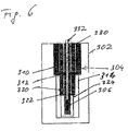
- FIG. 6 shows such a conventional arrangement having a cryostat vessel 302 that is evacuated.
- a cooling device 304 and a microscopy device 306 are arranged in the cryostat vessel 302 .
- the cooling device 304 comprises a nitrogen cooler 310 with liquid nitrogen as coolant.
- the nitrogen cooler 310 is connected to a 70K cold shield 314 via a thermal 70K coupling 312 .
- a helium cooler 320 Arranged concentrically in the nitrogen cooler 310 with 70K cold shield 314 is a helium cooler 320 that is thermally coupled to a 4K cold shield 324 via a 4K coupling 322 .
- a sample tube 330 is arranged concentrically relative to the helium cooler 320 with 4K cold shield 322 , and relative to the nitrogen cooler 310 with 70K cold shield 314 .
- the thermal connection between the sample tube 330 and the nitrogen cooler 310 and/or the helium cooler 320 is performed by a mechanical, and therefore thermal connection of the sample tube 330 to the 70K coupling 314 and/or the 4K coupling 324 .
- a sample rod or dipstick 332 is inserted into the sample tube 330 , and a confocal microscope 334 is arranged at its lower end.
- Cooling with the aid of liquid nitrogen and liquid helium is disadvantageous in this known apparatus, since handling liquid nitrogen and liquid helium is complicated and awkward. Moreover, the use of liquid helium is expensive.
- FIG. 1 shows a schematic of a first embodiment of the invention having a single-stage pulse tube cooler
- FIG. 2 shows a second embodiment of the invention having a two-stage pulse tube cooler
- FIG. 3 shows a detailed illustration of the confocal microscope of the second embodiment of the invention having a piezo positioning apparatus
- FIG. 4 shows a detailed illustration, corresponding to FIG. 3 , of a third embodiment of the invention having an atomic force or scanning tunneling microscope instead of the confocal microscope;
- FIG. 5 shows a fourth embodiment of the invention having a ADR cooling stage, a 100 mK cooling stage and a confocal microscope
- FIG. 6 shows a low temperature cryostat according to the prior art.
- pulse tube coolers can certainly be configured because of vibration, but their functionality dictates that they have vibrations in the low frequency 1 Hz range that cannot be eliminated. These vibrations originate from the oscillating gas column in the pulse tube cooler. These vibrations cause a deflection of the cold head of the pulse tube cooler in the ⁇ m region. The use of pulse tube coolers has so far been refrained from because of these vibrations that cannot be eliminated.
- the component of a pulse tube cooler that still most readily also generates high frequency vibrations in addition to the low frequency vibrations is arranged outside the cryostat vessel and is connected to the latter by means of a flexible hose line. This prevents the high frequency vibrations from impairing the mode of operation of the microscopy device, and at the same time the low frequency vibrations are reduced. Consequently, it is only the low frequency vibrations that still occur in the cryostat vessel on the basis of the oscillating gas.
- the thermal coupling of the microscopy device to the pulse tube cooling system is designed in an elastic and vibration damping fashion. Consequently, the low frequency vibrations still occurring from the pulse tube cooling system are strongly damped and are therefore less able to have a disturbing effect on the microscopy device. Moreover, account is thereby taken of the unavoidable changes in length between ambient temperature and the temperature of the sample.
- Such a low temperature cryostat can be used with a multiplicity of different microscopy devices such as confocal microscope, tunneling microscope, atomic force microscope, magnetic microscope, chemical microscope etc.
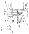
- FIG. 1 shows a schematic of the essential components of a first embodiment of the invention, in the case of which the basic concept of the invention is concerned.
- a cooling device 4 in the form of a single-stage pulse tube cooler 10 is arranged in a cryostat vessel 2 .
- the pulse tube cooler 10 comprises a pulse tube 12 and a regenerator 14 that are arranged between a cold head 16 and a valve head 18 .
- a microscopy device 6 is mechanically and thermally coupled to the cold head 16 by means of a thermal coupling 8 .
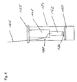
- FIG. 2 shows a second embodiment having a cryostat vessel 102 , a cooling device 104 , arranged in the cryostat vessel 102 , in the form of a two-stage pulse tube cooling system 110 .
- the pulse tube cooling system 110 has a first pulse tube cooler 111 and a second pulse tube cooler 121 .
- the first pulse tube cooler 111 has a first pulse tube 112 and a first regenerator 113 .
- the first pulse tube 112 and the first regenerator 113 are arranged between a valve head 114 and a 60K cold head 115 .
- the second pulse tube cooler 121 has a second pulse tube 122 and a second regenerator 123 .
- the second pulse tube 122 is arranged between the valve head 114 and a 4K cold head 125 , and the second regenerator 123 is arranged between the 60K cold head 115 and the 4K cold head 125 .
- a ballast volume 116 is directly connected to the valve head 114 arranged outside the cryostat vessel 102 .
- the valve head 114 and the ballast volume 116 are connected to a turning valve 118 via a flexible hose 117 .
- a sample tube 130 Arranged in the cryostat vessel 102 is a sample tube 130 that is accessible from the outside and into which a sample rod 132 can be inserted.
- the sample rod 132 has a warm end 134 , which projects from the cryostat vessel 102 , and a cold end 136 , which comes to lie in the interior of the cryostat vessel 102 .
- a confocal microscope 138 is arranged in the region of the cold end 136 of the sample rod 132 .
- the sample tube 130 and thus the sample rod 132 with the confocal microscope 138 are connected thermally to the 60K cold head 115 via a 60K coupling 140 , and to the 4K cold head 125 of the cooling device 104 via a 4K coupling 142 .
- the 60K coupling 140 is arranged closer at the warm end 134
- the 4K coupling 142 is arranged in the region of the cold end 136 .
- the sample rod 132 is arranged concentrically in the sample tube 130 .
- the sample tube 130 has a hollow cladding 144 that can be evacuated or filled with exchange gas.
- vibrations of the turning valve 118 are strongly damped, and scarcely any vibrations are transmitted onto the cryostat vessel.
- vibrations from the pulse tube cooling system are likewise strongly damped, and so scarcely any vibrations are transmitted onto the sample tube 130 , and thus onto the confocal microscope 138 .
- a braided ground strap made from electrolytic copper is well suited therefor.
- FIG. 3 shows a detail of the third embodiment of the invention, specifically the cold end 136 of the sample rod 132 with the confocal microscope 138 .
- the confocal microscope 138 comprises a lens arrangement 146 that is thermally and mechanically connected to the 4K coupling 142 by means of a piezo positioning apparatus 148 .
- a sample 150 to be examined is arranged below the lens arrangement 146 .
- the light that originates from a light source (not illustrated), is reflected by the sample 150 and falls into the lens arrangement 146 is guided out of the cryostat vessel 102 via an optical fiber 152 .
- the viewing light is preferably likewise coupled in via the optical fiber 152 .
- the focusing of the lens arrangement 146 is performed by the piezo apparatus 148 .
- the lens arrangement 146 can be moved and positioned on three spatial axes relative to the sample 150 with the aid of the piezo positioning apparatus 148 .
- the entire arrangement is surrounded by a cladding 154 that is part
- FIG. 4 shows a detail of a third embodiment of the invention, in the case of which instead of a confocal microscope an atomic force or scanning tunneling microscope 160 is provided in the cryostat design according to FIG. 2 .
- Components are correspondingly provided with the same reference numerals in FIGS. 3 and 4 .
- the third embodiment of the invention differs from the second embodiment only in that a carrier unit 162 for a scanning tip 164 is provided instead of the lens arrangement 146 , and an electric signal line 166 is provided instead of the light guide 152 .
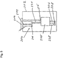
- FIG. 5 shows a fourth embodiment of the invention having a cryostat vessel 202 in which a cooling device 204 is accommodated.
- the cooling device 204 arranged in the cryostat vessel 202 comprises a two-stage pulse tube cooling system 210 having a first pulse tube cooler 211 with a first cold head 215 , and a second pulse tube cooler 221 with a second cold head 225 .
- the interface to the outside is provided via a valve head 214 .
- the remaining components such as turning valve and ballast volume, for example, are not illustrated.
- the two-stage pulse tube cooling system 210 comes close to the pulse tube cooling system from FIG. 2 .
- the two-stage pulse tube cooling system 210 precools an adiabatic demagnetization cooling stage or an ADR cooling stage 205 , having a magnet that is not, illustrated, to approximately 4K.
- the ADR stage 205 is thermally and mechanically coupled to the second cold head 225 of the two-stage pulse tube cooling system 210
- the confocal microscope 238 with positioning apparatus (not illustrated) is arranged at the magnet (not illustrated) of the ADR cooling stage 205 .
- the confocal microscope 238 is thereby thermally coupled to the second cold head 225 and is cooled to approximately 4K.
- the ADR cooling stage 205 cools to approximately 100 mK.
- a sample 208 is thermally coupled to the ADR cooling stage 205 via a sample holder 206 , such that the sample is cooled to approximately 100 mK.
Landscapes
- Engineering & Computer Science (AREA)
- Physics & Mathematics (AREA)
- Mechanical Engineering (AREA)
- Thermal Sciences (AREA)
- General Engineering & Computer Science (AREA)
- Chemical & Material Sciences (AREA)
- Combustion & Propulsion (AREA)
- Microscoopes, Condenser (AREA)
Abstract
A low temperature cryostat is disclosed. The low temperature cryostat may include a cryostat vessel, a cooling device arranged in the cryostat vessel for producing a cooling temperature level, a microscopy device for examining a sample, and at least one thermal coupling for thermally and mechanically connecting the microscopy device to the cooling device. The cooling device may comprise a pulse tube cooling system.
Description
- This application claims priority to Patent Cooperation Treaty Application Number PCT/EP2005/056316 filed Nov. 29, 2005, which claims priority to German Application DE 20 2004 018 469.9 filed Nov. 29, 2004, both of which contents are incorporated herein by reference.
- A portion of the disclosure of this patent document contains material which is subject to copyright protection. This patent document may show and/or describe matter which is or may become trade dress of the owner. The copyright and trade dress owner has no objection to the facsimile reproduction by anyone of the patent disclosure as it appears in the Patent and Trademark Office patent files or records, but otherwise reserves all copyright and trade dress rights whatsoever.
- 1. Field
- This disclosure relates to a low temperature cryostat.
- 2. Description of the Related Art
- It is conventional to make use in low temperature microscopy of sample tubes in which the respective microscope is arranged. The sample tubes are inserted into 4K cryostats and cooled by means of liquid nitrogen (77K) and liquid helium (4K). A so-called dipstick with a sample to be examined and a microscope is inserted into the sample tube and cooled. The sample tube itself can in this case be evacuated or be filled with exchange gas for the purpose of better thermal coupling to the liquid nitrogen and the liquid helium.
-
FIG. 6 shows such a conventional arrangement having acryostat vessel 302 that is evacuated. Acooling device 304 and amicroscopy device 306 are arranged in thecryostat vessel 302. Thecooling device 304 comprises anitrogen cooler 310 with liquid nitrogen as coolant. Thenitrogen cooler 310 is connected to a 70Kcold shield 314 via athermal 70K coupling 312. Arranged concentrically in thenitrogen cooler 310 with 70Kcold shield 314 is ahelium cooler 320 that is thermally coupled to a 4Kcold shield 324 via a4K coupling 322. Asample tube 330 is arranged concentrically relative to thehelium cooler 320 with 4Kcold shield 322, and relative to thenitrogen cooler 310 with 70Kcold shield 314. The thermal connection between thesample tube 330 and thenitrogen cooler 310 and/or thehelium cooler 320 is performed by a mechanical, and therefore thermal connection of thesample tube 330 to the70K coupling 314 and/or the4K coupling 324. A sample rod ordipstick 332 is inserted into thesample tube 330, and a confocal microscope 334 is arranged at its lower end. - Cooling with the aid of liquid nitrogen and liquid helium is disadvantageous in this known apparatus, since handling liquid nitrogen and liquid helium is complicated and awkward. Moreover, the use of liquid helium is expensive.
- It is therefore an object of the present invention to specify a low temperature cryostat that is easier to handle and more cost-effective in operation.
- This object is achieved by means of a low temperature cryostat in accordance with the features of claim 1.
- Further details, features and advantages of the invention emerge from the following description of preferred embodiments of the invention with the aid of the drawings, in which:
-
FIG. 1 shows a schematic of a first embodiment of the invention having a single-stage pulse tube cooler; -
FIG. 2 shows a second embodiment of the invention having a two-stage pulse tube cooler; -
FIG. 3 shows a detailed illustration of the confocal microscope of the second embodiment of the invention having a piezo positioning apparatus; -
FIG. 4 shows a detailed illustration, corresponding toFIG. 3 , of a third embodiment of the invention having an atomic force or scanning tunneling microscope instead of the confocal microscope; -
FIG. 5 shows a fourth embodiment of the invention having a ADR cooling stage, a 100 mK cooling stage and a confocal microscope; -
FIG. 6 shows a low temperature cryostat according to the prior art. - Throughout this description, the embodiments and examples shown should be considered as exemplars, rather than limitations on the apparatus and methods disclosed or claimed.
- Since it is impermissible in low temperature microscopy to transmit vibrations onto the sample, there has so far been no use of mechanical cooling devices such as compressors and pulse tube coolers. Compressor cooling devices have a broad spectrum of vibrations from the low frequency up to the high frequency range, and are therefore unsuitable as a replacement for nitrogen/helium coolers. Given appropriate design, pulse tube coolers can certainly be configured because of vibration, but their functionality dictates that they have vibrations in the low frequency 1 Hz range that cannot be eliminated. These vibrations originate from the oscillating gas column in the pulse tube cooler. These vibrations cause a deflection of the cold head of the pulse tube cooler in the □m region. The use of pulse tube coolers has so far been refrained from because of these vibrations that cannot be eliminated. However, it has been shown that when use is made of pulse tube coolers these low frequency vibrations are by far less disturbing than assumed. This is likely to be ascribed to the fact that the microscope device connected to the cold head covibrates synchronously because of the low frequencies, and this oscillation is therefore not disturbing.
- In accordance with an advantageous refinement of the invention, the component of a pulse tube cooler that still most readily also generates high frequency vibrations in addition to the low frequency vibrations, specifically the turning valve, is arranged outside the cryostat vessel and is connected to the latter by means of a flexible hose line. This prevents the high frequency vibrations from impairing the mode of operation of the microscopy device, and at the same time the low frequency vibrations are reduced. Consequently, it is only the low frequency vibrations that still occur in the cryostat vessel on the basis of the oscillating gas.
- In accordance with a further preferred refinement of the invention, the thermal coupling of the microscopy device to the pulse tube cooling system is designed in an elastic and vibration damping fashion. Consequently, the low frequency vibrations still occurring from the pulse tube cooling system are strongly damped and are therefore less able to have a disturbing effect on the microscopy device. Moreover, account is thereby taken of the unavoidable changes in length between ambient temperature and the temperature of the sample.
- Such a low temperature cryostat can be used with a multiplicity of different microscopy devices such as confocal microscope, tunneling microscope, atomic force microscope, magnetic microscope, chemical microscope etc.
- The remaining subclaims relate to further advantageous refinements of the invention.
-
FIG. 1 shows a schematic of the essential components of a first embodiment of the invention, in the case of which the basic concept of the invention is concerned. Acooling device 4 in the form of a single-stagepulse tube cooler 10 is arranged in acryostat vessel 2. Thepulse tube cooler 10 comprises a pulse tube 12 and a regenerator 14 that are arranged between a cold head 16 and a valve head 18. Amicroscopy device 6 is mechanically and thermally coupled to the cold head 16 by means of athermal coupling 8. -
FIG. 2 shows a second embodiment having acryostat vessel 102, a cooling device 104, arranged in thecryostat vessel 102, in the form of a two-stage pulse tube cooling system 110. The pulse tube cooling system 110 has a first pulse tube cooler 111 and a secondpulse tube cooler 121. The first pulse tube cooler 111 has afirst pulse tube 112 and afirst regenerator 113. Thefirst pulse tube 112 and thefirst regenerator 113 are arranged between avalve head 114 and a 60Kcold head 115. The secondpulse tube cooler 121 has asecond pulse tube 122 and asecond regenerator 123. Thesecond pulse tube 122 is arranged between thevalve head 114 and a 4Kcold head 125, and thesecond regenerator 123 is arranged between the 60Kcold head 115 and the 4Kcold head 125. Aballast volume 116 is directly connected to thevalve head 114 arranged outside thecryostat vessel 102. Thevalve head 114 and theballast volume 116 are connected to a turningvalve 118 via aflexible hose 117. - Arranged in the
cryostat vessel 102 is asample tube 130 that is accessible from the outside and into which asample rod 132 can be inserted. Thesample rod 132 has awarm end 134, which projects from thecryostat vessel 102, and acold end 136, which comes to lie in the interior of thecryostat vessel 102. Aconfocal microscope 138 is arranged in the region of thecold end 136 of thesample rod 132. - The
sample tube 130, and thus thesample rod 132 with theconfocal microscope 138 are connected thermally to the 60Kcold head 115 via a60K coupling 140, and to the 4Kcold head 125 of the cooling device 104 via a 4K coupling 142. The60K coupling 140 is arranged closer at thewarm end 134, and the 4K coupling 142 is arranged in the region of thecold end 136. Thesample rod 132 is arranged concentrically in thesample tube 130. Thesample tube 130 has a hollow cladding 144 that can be evacuated or filled with exchange gas. - Owing to the spatially separated arrangement of the turning valve and its connection to the valve head via a
flexible hose 117, vibrations of the turningvalve 118 are strongly damped, and scarcely any vibrations are transmitted onto the cryostat vessel. Owing to the configuration of the60K coupling 140 and of the 4K coupling 142 in the form of an elastic strip made from material that effectively conducts heat, vibrations from the pulse tube cooling system are likewise strongly damped, and so scarcely any vibrations are transmitted onto thesample tube 130, and thus onto theconfocal microscope 138. A braided ground strap made from electrolytic copper is well suited therefor. -
FIG. 3 shows a detail of the third embodiment of the invention, specifically thecold end 136 of thesample rod 132 with theconfocal microscope 138. Theconfocal microscope 138 comprises alens arrangement 146 that is thermally and mechanically connected to the 4K coupling 142 by means of a piezo positioning apparatus 148. Asample 150 to be examined is arranged below thelens arrangement 146. The light that originates from a light source (not illustrated), is reflected by thesample 150 and falls into thelens arrangement 146 is guided out of thecryostat vessel 102 via anoptical fiber 152. The viewing light is preferably likewise coupled in via theoptical fiber 152. The focusing of thelens arrangement 146 is performed by the piezo apparatus 148. Thelens arrangement 146 can be moved and positioned on three spatial axes relative to thesample 150 with the aid of the piezo positioning apparatus 148. The entire arrangement is surrounded by acladding 154 that is part of thesample rod 132. -
FIG. 4 shows a detail of a third embodiment of the invention, in the case of which instead of a confocal microscope an atomic force or scanningtunneling microscope 160 is provided in the cryostat design according toFIG. 2 . Components are correspondingly provided with the same reference numerals inFIGS. 3 and 4 . The third embodiment of the invention differs from the second embodiment only in that acarrier unit 162 for ascanning tip 164 is provided instead of thelens arrangement 146, and an electric signal line 166 is provided instead of thelight guide 152. -
FIG. 5 shows a fourth embodiment of the invention having acryostat vessel 202 in which acooling device 204 is accommodated. Thecooling device 204 arranged in thecryostat vessel 202 comprises a two-stage pulse tube cooling system 210 having a first pulse tube cooler 211 with a first cold head 215, and a second pulse tube cooler 221 with a secondcold head 225. The interface to the outside is provided via avalve head 214. The remaining components such as turning valve and ballast volume, for example, are not illustrated. The two-stage pulse tube cooling system 210 comes close to the pulse tube cooling system fromFIG. 2 . The two-stage pulse tube cooling system 210 precools an adiabatic demagnetization cooling stage or anADR cooling stage 205, having a magnet that is not, illustrated, to approximately 4K. TheADR stage 205 is thermally and mechanically coupled to the secondcold head 225 of the two-stage pulse tube cooling system 210 Theconfocal microscope 238 with positioning apparatus (not illustrated) is arranged at the magnet (not illustrated) of theADR cooling stage 205. Theconfocal microscope 238 is thereby thermally coupled to the secondcold head 225 and is cooled to approximately 4K. TheADR cooling stage 205 cools to approximately 100 mK. Asample 208 is thermally coupled to theADR cooling stage 205 via asample holder 206, such that the sample is cooled to approximately 100 mK. - The above-described embodiments of the invention may also be combined with one another. It is likewise possible, for example, to arrange a number of different microscopes in the cryostat vessel.
-
- 2 Cryostat vessel
- 4 Cooling device
- 6 Microscopy device
- 8 Thermal coupling
- 10 Pulse tube cooler
- 12 Pulse tube
- 14 Regenerator
- 16 Cold head
- 18 Valve head
- 102 Cryostat vessel
- 104 Cooling device
- 110 Two-stage pulse tube cooling system
- 111 First pulse tube cooler
- 112 First pulse tube
- 113 First regenerator
- 114 Valve head
- 115 60K cold head
- 116 Ballast volume
- 117 Flexible hose
- 118 Turning valve
- 121 Second pulse tube cooler
- 122 Second pulse tube
- 123 Second regenerator
- 125 4K cold head
- 130 Sample tube
- 132 Sample rod
- 134 Warm end of 132
- 136 Cold end of 132
- 138 Confocal microscope
- 140 60K coupling
- 142 4K coupling
- 144 Cladding of 130
- 146 Lens arrangement
- 148 Piezo apparatus
- 150 Sample
- 152 Optical fiber
- 160 AFM or scanning tunneling microscope
- 162 Carrier unit for 164
- 164 Scanning tip
- 166 Electric signal line
- 202 Cryostat vessel
- 204 Cooling device
- 205 ADR cooling stage
- 206 Sample holder
- 208 Sample
- 210 Two-stage pulse tube cooling system
- 211 First pulse tube cooler
- 214 Valve head
- 215 First cold head
- 221 Second pulse tube cooler
- 225 Second cold head
- 238 Confocal microscope
- 302 Cryostat vessel
- 304 Cooling device
- 306 Microscopy device
- 310 Nitrogen cooler
- 312 70K coupling
- 314 70K cold shield
- 320 Helium cooler
- 322 4K coupling
- 324 4K cold shield
- 330 Sample tube
- 332 Sample rod (dipstick)
- Closing Comments
- The foregoing is merely illustrative and not limiting, having been presented by way of example only. Although examples have been shown and described, it will be apparent to those having ordinary skill in the art that changes, modifications, and/or alterations may be made.
Claims (13)
1. A low temperature cryostat having
a cryostat vessel,
a cooling device, arranged in the cryostat vessel, for producing a cooling temperature level TK,
a microscopy device for examining a sample, and
at least one thermal coupling for thermally and mechanically connecting the microscopy device to the cooling device, wherein
the cooling device comprises a pulse tube cooling system.
2. The low temperature cryostat as claimed in claim 1 , wherein the pulse tube cooling system comprises a turning valve that is arranged outside the cryostat vessel and is connected to the cryostat vessel via a vibration damping line.
3. The low temperature cryostat as claimed in claim 2 , wherein the vibration damping line is a flexible connecting hose.
4. The low temperature cryostat as claimed in one of the preceding claims, wherein the pulse tube cooling system is a single-stage pulse tube cooler.
5. The low temperature cryostat as claimed in one of the preceding claims 1 , wherein the pulse tube cooling system comprises a multistage, in particular two-stage pulse tube cooler.
6. The low temperature cryostat as claimed in claim 1 , wherein the thermal coupling of the microscopy device to the pulse tube cooling system is designed in an elastic and vibration damping fashion.
7. The low temperature cryostat as claimed in claim 1 , wherein the microscopy device is arranged in a sample tube.
8. The low temperature cryostat as claimed in claim 7 , wherein the sample tube can be inserted into the cryostat vessel and can be thermally coupled to the cooling device via the thermal coupling.
9. The low temperature cryostat as claimed in claim 1 , wherein the cooling device comprises a first cooling stage in the form of said pulse tube cooling system, and a second cooling stage for a cooling temperature level in the range <4K, and wherein the second cooling stage is precooled by the first cooling stage.
10. The low temperature cryostat as claimed in claim 9 , wherein the second cooling stage has an adiabatic demagnetization device or a 3 He/4 He dilution cooler or a 3 He cooler or a mechanical cooling device such as a helium compressor cooler, or an electric cooling device such as a Peltier element or a superconducting tunnel diode such as an NIS diode.
11. The low temperature cryostat as claimed in claim 1 , wherein the microscopy device comprises a confocal microscope.
12. The low temperature cryostat as claimed in claim 1 , wherein the microscopy device comprises a scanning tunneling microscope.
13. The low temperature cryostat as claimed in claim 1 , wherein the microscopy device comprises an atomic force microscope.
Applications Claiming Priority (3)
| Application Number | Priority Date | Filing Date | Title |
|---|---|---|---|
| DE202004018469U DE202004018469U1 (en) | 2004-11-29 | 2004-11-29 | Low-temperature cryostat |
| DE202004018469.9 | 2004-11-29 | ||
| PCT/EP2005/056315 WO2006061340A2 (en) | 2004-12-10 | 2005-11-29 | Stable, hormone-containing (intermediate) product |
Publications (1)
| Publication Number | Publication Date |
|---|---|
| US20080098752A1 true US20080098752A1 (en) | 2008-05-01 |
Family
ID=35587909
Family Applications (1)
| Application Number | Title | Priority Date | Filing Date |
|---|---|---|---|
| US11/720,354 Abandoned US20080098752A1 (en) | 2004-11-29 | 2005-11-29 | Low Temperature Cryostat |
Country Status (4)
| Country | Link |
|---|---|
| US (1) | US20080098752A1 (en) |
| EP (1) | EP1839001A1 (en) |
| DE (1) | DE202004018469U1 (en) |
| WO (1) | WO2006056619A1 (en) |
Cited By (5)
| Publication number | Priority date | Publication date | Assignee | Title |
|---|---|---|---|---|
| US20100089069A1 (en) * | 2007-06-22 | 2010-04-15 | Jens Hoehne | Low temperature device |
| WO2012127255A2 (en) | 2011-03-22 | 2012-09-27 | Institut Za Fiziku | Cryostat with ptr cooling and two stage sample holder thermalization |
| EP3163222A1 (en) * | 2015-10-28 | 2017-05-03 | Technische Universität München | Cryogen-free cooling apparatus |
| CN116294285A (en) * | 2023-03-28 | 2023-06-23 | 中国科学院理化技术研究所 | A kind of extremely low temperature refrigeration system and refrigeration method thereof |
| EP4491982A1 (en) * | 2023-07-10 | 2025-01-15 | Technische Universität München, in Vertretung des Freistaates Bayern | Apparatus for cooling a sample environment and method of protecting a sample from vibrations of a vessel of a continuously cooled dry cryostat |
Families Citing this family (1)
| Publication number | Priority date | Publication date | Assignee | Title |
|---|---|---|---|---|
| DE102011115303B4 (en) | 2011-09-29 | 2013-06-27 | Entropy GmbH | Cryogenic device |
Citations (9)
| Publication number | Priority date | Publication date | Assignee | Title |
|---|---|---|---|---|
| US4352643A (en) * | 1979-05-18 | 1982-10-05 | Fujitsu Limited | Structure for vibration isolation in an apparatus with a vacuum system |
| US4929831A (en) * | 1988-12-08 | 1990-05-29 | The United States Of America As Represented By The Secretary Of The Navy | Electron beam apparatus for testing infrared detectors in a cryogenically shielded environment |
| US5522223A (en) * | 1994-10-21 | 1996-06-04 | Iwatani Sangyo Kabushiki Kaisha | Pulse tube refrigerator |
| US5628195A (en) * | 1995-03-01 | 1997-05-13 | Apd Cryogenics, Inc. | Vibrationally isolated thermal system for a cryogenically cooled device |
| US5811816A (en) * | 1995-06-26 | 1998-09-22 | U.S. Philips Corporation | Closed cycle gas cryogenically cooled radiation detector |
| US5816052A (en) * | 1997-02-24 | 1998-10-06 | Noran Instruments, Inc. | Method and apparatus for mechanically cooling energy dispersive X-ray spectrometers |
| US6516281B1 (en) * | 1998-12-10 | 2003-02-04 | University Of Maryland | Scanning single electron transistor microscope for imaging ambient temperature objects |
| US6573509B2 (en) * | 2001-02-27 | 2003-06-03 | Oxford Instruments Analytical Limited | Detection system |
| US20030163996A1 (en) * | 2002-01-22 | 2003-09-04 | Alain Ravex | Apparatus and method for extracting cooling power from helium in a cooling system regenerator |
Family Cites Families (9)
| Publication number | Priority date | Publication date | Assignee | Title |
|---|---|---|---|---|
| JPH0772650B2 (en) | 1992-09-25 | 1995-08-02 | 岩谷産業株式会社 | Element cooling device for EDS detector |
| DE19548273A1 (en) * | 1995-12-22 | 1997-06-26 | Spectrospin Ag | NMR measuring device with pulse tube cooler |
| DE19612539A1 (en) * | 1996-03-29 | 1997-10-02 | Leybold Vakuum Gmbh | Multi-stage cryogenic refrigerator |
| DE19648253C2 (en) * | 1996-11-22 | 2002-04-04 | Siemens Ag | Pulse tube cooler and use of the same |
| JP3981185B2 (en) * | 1997-05-10 | 2007-09-26 | 株式会社堀場製作所 | Energy dispersive semiconductor X-ray detector |
| JP3577661B2 (en) * | 1999-09-29 | 2004-10-13 | 住友重機械工業株式会社 | Pulse tube refrigerator |
| DE19954077C1 (en) * | 1999-11-10 | 2001-03-22 | Csp Cryogenic Spectrometers Gm | Low temperature cooling device for superconductivity or semiconductor elements or sensors, has two pulse tube coolers providing different temperatures and regenerator |
| DE10164428A1 (en) * | 2001-12-29 | 2003-07-17 | Feilitzsch Franz Von | X-ray spectroscopy device, incorporates SQUID and allows continuous high resolution measurement of energy of X-ray quanta emitted from electron beam activated sample |
| DE10210524C1 (en) * | 2002-03-09 | 2003-08-14 | Inst Luft Kaeltetech Gem Gmbh | Cryogenic cooling unit includes positive displacement micropump, condenser, interception chamber, and sub-cooling heat exchanger |
-
2004
- 2004-11-29 DE DE202004018469U patent/DE202004018469U1/en not_active Expired - Lifetime
-
2005
- 2005-11-29 EP EP05815513A patent/EP1839001A1/en not_active Withdrawn
- 2005-11-29 WO PCT/EP2005/056316 patent/WO2006056619A1/en not_active Ceased
- 2005-11-29 US US11/720,354 patent/US20080098752A1/en not_active Abandoned
Patent Citations (9)
| Publication number | Priority date | Publication date | Assignee | Title |
|---|---|---|---|---|
| US4352643A (en) * | 1979-05-18 | 1982-10-05 | Fujitsu Limited | Structure for vibration isolation in an apparatus with a vacuum system |
| US4929831A (en) * | 1988-12-08 | 1990-05-29 | The United States Of America As Represented By The Secretary Of The Navy | Electron beam apparatus for testing infrared detectors in a cryogenically shielded environment |
| US5522223A (en) * | 1994-10-21 | 1996-06-04 | Iwatani Sangyo Kabushiki Kaisha | Pulse tube refrigerator |
| US5628195A (en) * | 1995-03-01 | 1997-05-13 | Apd Cryogenics, Inc. | Vibrationally isolated thermal system for a cryogenically cooled device |
| US5811816A (en) * | 1995-06-26 | 1998-09-22 | U.S. Philips Corporation | Closed cycle gas cryogenically cooled radiation detector |
| US5816052A (en) * | 1997-02-24 | 1998-10-06 | Noran Instruments, Inc. | Method and apparatus for mechanically cooling energy dispersive X-ray spectrometers |
| US6516281B1 (en) * | 1998-12-10 | 2003-02-04 | University Of Maryland | Scanning single electron transistor microscope for imaging ambient temperature objects |
| US6573509B2 (en) * | 2001-02-27 | 2003-06-03 | Oxford Instruments Analytical Limited | Detection system |
| US20030163996A1 (en) * | 2002-01-22 | 2003-09-04 | Alain Ravex | Apparatus and method for extracting cooling power from helium in a cooling system regenerator |
Cited By (12)
| Publication number | Priority date | Publication date | Assignee | Title |
|---|---|---|---|---|
| US20100089069A1 (en) * | 2007-06-22 | 2010-04-15 | Jens Hoehne | Low temperature device |
| US9062905B2 (en) * | 2007-06-22 | 2015-06-23 | Hb Patent Unternehmergesellschaft | Low temperature device with low-vibration sample holding device |
| WO2012127255A2 (en) | 2011-03-22 | 2012-09-27 | Institut Za Fiziku | Cryostat with ptr cooling and two stage sample holder thermalization |
| WO2012127255A3 (en) * | 2011-03-22 | 2012-11-08 | Institut Za Fiziku | Cryostat with ptr cooling and two stage sample holder thermalization |
| US20140007596A1 (en) * | 2011-03-22 | 2014-01-09 | Institut Za Fiziku | Cryostat with ptr cooling and two stage sample holder thermalization |
| US9458969B2 (en) * | 2011-03-22 | 2016-10-04 | Institut Za Fiziku | Cryostat with PTR cooling and two stage sample holder thermalization |
| EP3163222A1 (en) * | 2015-10-28 | 2017-05-03 | Technische Universität München | Cryogen-free cooling apparatus |
| WO2017072174A1 (en) * | 2015-10-28 | 2017-05-04 | Technische Universität München | Cryogen-free cooling apparatus |
| US11486611B2 (en) | 2015-10-28 | 2022-11-01 | Kiutra Gmbh | Cryogen-free cooling apparatus |
| CN116294285A (en) * | 2023-03-28 | 2023-06-23 | 中国科学院理化技术研究所 | A kind of extremely low temperature refrigeration system and refrigeration method thereof |
| EP4491982A1 (en) * | 2023-07-10 | 2025-01-15 | Technische Universität München, in Vertretung des Freistaates Bayern | Apparatus for cooling a sample environment and method of protecting a sample from vibrations of a vessel of a continuously cooled dry cryostat |
| WO2025011829A1 (en) * | 2023-07-10 | 2025-01-16 | Technische Universität München, in Vertretung des Freistaates Bayern | Apparatus for cooling a sample environment, sample holder, and method of protecting a sample from vibrations of a vessel of a continuously cooled dry cryostat |
Also Published As
| Publication number | Publication date |
|---|---|
| DE202004018469U1 (en) | 2006-04-13 |
| WO2006056619A1 (en) | 2006-06-01 |
| EP1839001A1 (en) | 2007-10-03 |
Similar Documents
| Publication | Publication Date | Title |
|---|---|---|
| US7191601B2 (en) | Magnetic field generating assembly | |
| US6389821B2 (en) | Circulating cryostat | |
| US5782095A (en) | Cryogen recondensing superconducting magnet | |
| US5508613A (en) | Apparatus for cooling NMR coils | |
| US7474099B2 (en) | NMR apparatus with commonly cooled probe head and cryogenic container and method for the operation thereof | |
| JP4031121B2 (en) | Cryostat equipment | |
| CN100580824C (en) | Magnetic resonance components and superconducting magnet systems | |
| US11137193B2 (en) | Cryogenic cooling apparatus | |
| US7222490B2 (en) | NMR spectrometer with refrigerator cooling | |
| US20140130520A1 (en) | Apparatus and methods for improving vibration isolation, thermal dampening, and optical access in cryogenic refrigerators | |
| JP2005024184A (en) | Cryogenic cooling device | |
| US20080098752A1 (en) | Low Temperature Cryostat | |
| JP5283096B2 (en) | Cryogenic cooling device | |
| JP6229207B2 (en) | Device for reducing vibration of pulse tube refrigerators used in magnetic resonance diagnostic imaging equipment | |
| JP4472715B2 (en) | Cryogenic refrigerator | |
| JP2014052133A (en) | Bayonet coupler for cryogenic fluid | |
| CN117347332A (en) | Scanning magnetic detection system | |
| JP2009052881A (en) | Extremely low temperature cooling device | |
| JP2010003943A (en) | Heat insulating support and superconducting apparatus equipped with the heat insulating support | |
| CN117347334A (en) | Detection devices for scanning magnetic detection systems | |
| US20090275476A1 (en) | Cryostat assembly | |
| WO2013125471A1 (en) | Cooling source for circulation cooling system and ion microscope using same | |
| JP4079101B2 (en) | Superconducting magnet apparatus and magnetic resonance imaging apparatus using the same | |
| CN117347333A (en) | Connecting tubes and transfer devices for scanning magnetic detection systems | |
| CN117571440A (en) | Refrigeration device for scanning magnetic detection systems |
Legal Events
| Date | Code | Title | Description |
|---|---|---|---|
| AS | Assignment |
Owner name: VERICOLD TECHNOLOGIES GMBH, GERMANY Free format text: ASSIGNMENT OF ASSIGNORS INTEREST;ASSIGNOR:HOHNE, JENS;REEL/FRAME:019350/0398 Effective date: 20070524 |
|
| STCB | Information on status: application discontinuation |
Free format text: ABANDONED -- FAILURE TO RESPOND TO AN OFFICE ACTION |