US20080098709A1 - Jewelry chain holder - Google Patents
Jewelry chain holder Download PDFInfo
- Publication number
- US20080098709A1 US20080098709A1 US11/580,752 US58075206A US2008098709A1 US 20080098709 A1 US20080098709 A1 US 20080098709A1 US 58075206 A US58075206 A US 58075206A US 2008098709 A1 US2008098709 A1 US 2008098709A1
- Authority
- US
- United States
- Prior art keywords
- jewelry
- chains
- holder
- chain holder
- container
- Prior art date
- Legal status (The legal status is an assumption and is not a legal conclusion. Google has not performed a legal analysis and makes no representation as to the accuracy of the status listed.)
- Granted
Links
Images

Classifications
-
- A—HUMAN NECESSITIES
- A45—HAND OR TRAVELLING ARTICLES
- A45C—PURSES; LUGGAGE; HAND CARRIED BAGS
- A45C11/00—Receptacles for purposes not provided for in groups A45C1/00-A45C9/00
- A45C11/16—Jewel boxes
Definitions
- This invention relates to a novel jewelry chain holder. More specifically, the present invention relates to a jewelry cain holder adapted to receive and hold a plurality of jewelry chains of varying lengths in a manner such that the chains will not become entangled or twisted while stationary.
- U.S. Pat. No. 5,833,052 issued on Nov. 10, 1998 discloses a jewelry chain holding structure which meets the foregoing criteria.
- the structure described therein includes a container having a rectangular configuration having disposed therein a jewelry chain holder which precludes jewelry chains from becoming entangled and knotted during the storage stage.
- the patented structure described therein comprises a container having an elongated rectangular configuration.
- the container has an open upper end and an open lower end and opposing side walls.
- the container also includes a pair of longitudinal grooves formed interiorly on two of the opposing walls. The grooves described begin at the open upper end and extend to a steep point disposed above the open lower end.
- a jewelry chain holder is then slidably coupled within the container.
- the patented chain holder insert comprises an inverted U-shaped handle having a short horizontal segment and a pair of elongated vertical segments extending downwardly from opposed open ends of the short horizontal segment.
- the jewelry chain holder also includes a t-shaped cross bar secured between the vertical segments of the handle. The t-shaped crossbar has engaging teeth formed in an upper surface which are adapted for receiving jewelry chains in a folded orientation.
- a novel jewelry holding chain structure capable of holding a plurality of jewelry chains of lengths varying from 14 inches to 20 inches.
- the described structure includes a container having an open upper end which may suitably be closed by affixing a rectangular cap thereto after insertion of the chains to be stored, and a closed bottom end.
- the inventive concept involves the insertion into the container of a novel jewelry chain holder which is adapted to receive jewelry chains of varying lengths within the range of 14 to 20 inches.
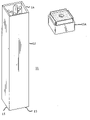
- FIG. 1 is a front elevational view in perspective of a jewelry chain holder container in accordance with the present invention
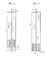
- FIG. 2 is a front elevational view of the jewelry holder insert in accordance with the present invention.
- FIG. 3 is a front elevational view of a second jewelry holder insert in accordance with the present invention.
- FIG. 1 there is shown a front elevational view in perspective of the jewelry holder container employed in the practice of the present invention.
- Jewelry holder 11 includes a container 12 having a rectangular configuration which is closed at the lower end 13 and open at the upper end 14 .
- the preferred construction of container 12 is a rigid plastic material such as Lucite. As indicated, container has an open upper end 14 and opposing side walls 15 and cap 15 A.
- FIG. 2 Shown in FIG. 2 is a jewelry chain holder of the present invention 16 dimensioned for coupling within container 12 .
- Holder 16 includes a flat inverted U-shaped handle 17 comprising an integral part of the jewelry holder 16 which has four plastic holders 18 , each having a U-shaped top surface 19 and an inverted U-shaped bottom surface 20 wherein the depth of the U-shape is permitted to vary to accommodate chains ranging from 14 to 20 inches in length. Also shown is t-shaped base 21 which rests at the bottom of jewelry holder 16 at the lower end thereof.
- the engaging teeth receive the jewelry chains in folded orientation at the upper surface and the bottom surface of the chain is inserted in the inverted U-shaped engaging teeth of the lower portion of the holder, the inverted U-shaped engaging teeth being selected to accommodate chains ranging from 14 to 18 inches in length.
- the holder After storing chains of varying lengths in holder 17 , the holder is inserted into container 12 until the base reaches the bottom thereof. Then cap 15 A is inserted on the open end of container 12 and the structure is then ready for storage.
- FIG. 3 is a front elevational view of another jewelry holder 31 of the type shown in FIG. 2 with the exception that holder 31 is structured such that it is capable of accommodating jewelry chains ranging in length from 18 to 20 inches.
- the primary distinction in this structure is the variation in the dimensions of the inverted U-shaped structures 32 at the bottom end thereof wherein the base member 33 is of equal length with the inverted U-shaped members 32 which are designed such that they are capable of accommodating longer chains.
Landscapes
- Purses, Travelling Bags, Baskets, Or Suitcases (AREA)
Abstract
Description
- Jewelry chain holders have been described heretofore for holding chains in a manner such that they will not become tangled or knotted. And although some of the structures described heretofore have been successfully employed for this purpose, it has been recognized by those skilled in the art that certain limitations are inherent therein.
- 1. Field of the Invention
- This invention relates to a novel jewelry chain holder. More specifically, the present invention relates to a jewelry cain holder adapted to receive and hold a plurality of jewelry chains of varying lengths in a manner such that the chains will not become entangled or twisted while stationary.
- 2. Description of the Prior Art
- In as classical example of a jewelry holder meeting the aforementioned criteria, U.S. Pat. No. 5,833,052 issued on Nov. 10, 1998 discloses a jewelry chain holding structure which meets the foregoing criteria. The structure described therein includes a container having a rectangular configuration having disposed therein a jewelry chain holder which precludes jewelry chains from becoming entangled and knotted during the storage stage.
- The patented structure described therein comprises a container having an elongated rectangular configuration. The container has an open upper end and an open lower end and opposing side walls. The container also includes a pair of longitudinal grooves formed interiorly on two of the opposing walls. The grooves described begin at the open upper end and extend to a steep point disposed above the open lower end. A jewelry chain holder is then slidably coupled within the container. The patented chain holder insert comprises an inverted U-shaped handle having a short horizontal segment and a pair of elongated vertical segments extending downwardly from opposed open ends of the short horizontal segment. The jewelry chain holder also includes a t-shaped cross bar secured between the vertical segments of the handle. The t-shaped crossbar has engaging teeth formed in an upper surface which are adapted for receiving jewelry chains in a folded orientation.
- Although the jewelry chain holder described in the aforementioned description has been found to be of great use for the purposes described therein, it has not proven to be of use in storing jewelry chains of varying lengths ranging from 14 inches to 20 inches.
- In accordance with the present invention, the prior art limitation alluded to above has been effectively obviated by means of a novel jewelry chain holder capable of holding jewelry chains of varying lengths without the need to be concerned about tangling and knotting issues.
- In the instant case, there is described a novel jewelry holding chain structure capable of holding a plurality of jewelry chains of lengths varying from 14 inches to 20 inches. The described structure includes a container having an open upper end which may suitably be closed by affixing a rectangular cap thereto after insertion of the chains to be stored, and a closed bottom end.
- The inventive concept involves the insertion into the container of a novel jewelry chain holder which is adapted to receive jewelry chains of varying lengths within the range of 14 to 20 inches.
- The invention will be more fully understood by reference to the following detailed description taken in conjunction with the accompanying drawing wherein
-
FIG. 1 is a front elevational view in perspective of a jewelry chain holder container in accordance with the present invention; -
FIG. 2 is a front elevational view of the jewelry holder insert in accordance with the present invention; and -
FIG. 3 is a front elevational view of a second jewelry holder insert in accordance with the present invention. - With reference now to
FIG. 1 , there is shown a front elevational view in perspective of the jewelry holder container employed in the practice of the present invention. -
Jewelry holder 11 includes acontainer 12 having a rectangular configuration which is closed at thelower end 13 and open at theupper end 14. The preferred construction ofcontainer 12 is a rigid plastic material such as Lucite. As indicated, container has an openupper end 14 and opposingside walls 15 andcap 15A. - Shown in
FIG. 2 is a jewelry chain holder of thepresent invention 16 dimensioned for coupling withincontainer 12.Holder 16 includes a flat invertedU-shaped handle 17 comprising an integral part of thejewelry holder 16 which has four plastic holders 18, each having a U-shaped top surface 19 and an inverted U-shaped bottom surface 20 wherein the depth of the U-shape is permitted to vary to accommodate chains ranging from 14 to 20 inches in length. Also shown is t-shaped base 21 which rests at the bottom ofjewelry holder 16 at the lower end thereof. - In use, the engaging teeth receive the jewelry chains in folded orientation at the upper surface and the bottom surface of the chain is inserted in the inverted U-shaped engaging teeth of the lower portion of the holder, the inverted U-shaped engaging teeth being selected to accommodate chains ranging from 14 to 18 inches in length.
- After storing chains of varying lengths in
holder 17, the holder is inserted intocontainer 12 until the base reaches the bottom thereof. Thencap 15A is inserted on the open end ofcontainer 12 and the structure is then ready for storage. -
FIG. 3 is a front elevational view of anotherjewelry holder 31 of the type shown inFIG. 2 with the exception thatholder 31 is structured such that it is capable of accommodating jewelry chains ranging in length from 18 to 20 inches. The primary distinction in this structure is the variation in the dimensions of the invertedU-shaped structures 32 at the bottom end thereof wherein thebase member 33 is of equal length with the invertedU-shaped members 32 which are designed such that they are capable of accommodating longer chains. - While the invention has been described in detail in the foregoing description, it will be appreciated by those skilled in the art that variations may be made without departing from the spirit and scope of the invention. Thus, for example, the dimensions of the inverted U-shaped structures at the base of the holder may be modified to accommodate chains of even greater length than those alluded to herein. Similarly, variations may be made in the construction of the jewelry holder without departing from the invention.
Claims (3)
Priority Applications (1)
| Application Number | Priority Date | Filing Date | Title |
|---|---|---|---|
| US11/580,752 US7789224B2 (en) | 2006-10-16 | 2006-10-16 | Jewelry chain holder |
Applications Claiming Priority (1)
| Application Number | Priority Date | Filing Date | Title |
|---|---|---|---|
| US11/580,752 US7789224B2 (en) | 2006-10-16 | 2006-10-16 | Jewelry chain holder |
Publications (2)
| Publication Number | Publication Date |
|---|---|
| US20080098709A1 true US20080098709A1 (en) | 2008-05-01 |
| US7789224B2 US7789224B2 (en) | 2010-09-07 |
Family
ID=39328497
Family Applications (1)
| Application Number | Title | Priority Date | Filing Date |
|---|---|---|---|
| US11/580,752 Expired - Fee Related US7789224B2 (en) | 2006-10-16 | 2006-10-16 | Jewelry chain holder |
Country Status (1)
| Country | Link |
|---|---|
| US (1) | US7789224B2 (en) |
Cited By (2)
| Publication number | Priority date | Publication date | Assignee | Title |
|---|---|---|---|---|
| US9833051B2 (en) * | 2016-02-19 | 2017-12-05 | Lasso It, Llc | Jewelry storage and display case |
| USD895286S1 (en) * | 2019-12-19 | 2020-09-08 | Zhushi Lin | Case for straw |
Families Citing this family (3)
| Publication number | Priority date | Publication date | Assignee | Title |
|---|---|---|---|---|
| US9078499B1 (en) | 2012-11-14 | 2015-07-14 | Nina Brabec | Necklace tangling prevention system |
| USD734037S1 (en) * | 2014-02-27 | 2015-07-14 | Jennifer Eckstein Coon | Necklace carrier |
| USD899771S1 (en) | 2017-08-08 | 2020-10-27 | Lasso It, Llc | Device for display and storage of jewelry |
Citations (4)
| Publication number | Priority date | Publication date | Assignee | Title |
|---|---|---|---|---|
| US4396121A (en) * | 1981-09-15 | 1983-08-02 | Lemmon Mildred K | Jewelry display box |
| US5117971A (en) * | 1991-05-17 | 1992-06-02 | Fisher Mildred K | Jewelry display box |
| US5168985A (en) * | 1991-03-12 | 1992-12-08 | Shih Yen Tieh | Jewel box |
| US5833052A (en) * | 1997-08-07 | 1998-11-10 | Diamond; Patricia Mary | Jewelry chain holding device |
-
2006
- 2006-10-16 US US11/580,752 patent/US7789224B2/en not_active Expired - Fee Related
Patent Citations (4)
| Publication number | Priority date | Publication date | Assignee | Title |
|---|---|---|---|---|
| US4396121A (en) * | 1981-09-15 | 1983-08-02 | Lemmon Mildred K | Jewelry display box |
| US5168985A (en) * | 1991-03-12 | 1992-12-08 | Shih Yen Tieh | Jewel box |
| US5117971A (en) * | 1991-05-17 | 1992-06-02 | Fisher Mildred K | Jewelry display box |
| US5833052A (en) * | 1997-08-07 | 1998-11-10 | Diamond; Patricia Mary | Jewelry chain holding device |
Cited By (7)
| Publication number | Priority date | Publication date | Assignee | Title |
|---|---|---|---|---|
| US9833051B2 (en) * | 2016-02-19 | 2017-12-05 | Lasso It, Llc | Jewelry storage and display case |
| US20180055168A1 (en) * | 2016-02-19 | 2018-03-01 | Colleen Chinlund | Jewelry Storage and Display Case |
| US10499717B2 (en) * | 2016-02-19 | 2019-12-10 | Lasso It, Llc | Jewelry storage and display case |
| US20200085158A1 (en) * | 2016-02-19 | 2020-03-19 | Colleen Chinlund | Jewelry storage and display case |
| US10827810B2 (en) * | 2016-02-19 | 2020-11-10 | Lasso It, Llc | Jewelry storage and display case |
| US11116299B2 (en) * | 2016-02-19 | 2021-09-14 | Colleen Chinlund | Personal item storage and display device |
| USD895286S1 (en) * | 2019-12-19 | 2020-09-08 | Zhushi Lin | Case for straw |
Also Published As
| Publication number | Publication date |
|---|---|
| US7789224B2 (en) | 2010-09-07 |
Similar Documents
| Publication | Publication Date | Title |
|---|---|---|
| US5458241A (en) | Storage device for decorative light string | |
| EP2777428A2 (en) | Adjustable ammunition magazine pouch | |
| KR100816144B1 (en) | Dental floss holder | |
| US10364123B2 (en) | Cable-cord wrapping apparatus | |
| US20110095155A1 (en) | Locking automobile mat hanger and display device | |
| US20110031136A1 (en) | Artist Brush Holder | |
| CN1298516C (en) | Power cord wrapping device for hair clippers | |
| JP2017512715A5 (en) | ||
| US8287020B1 (en) | Roll container | |
| US9936799B2 (en) | Broom holder | |
| US7789224B2 (en) | Jewelry chain holder | |
| US5784830A (en) | Fish hook removing devices | |
| US6886796B1 (en) | Elastic cord storage device | |
| US20070039912A1 (en) | Extension cord carrier | |
| US20180007881A1 (en) | Fishing lure storage container | |
| US6431489B1 (en) | Christmas light storage device | |
| US10342396B2 (en) | Towel dispensing system including a bracket and water-resistant container with a handle | |
| US20050183245A1 (en) | Line-securing device | |
| US5833052A (en) | Jewelry chain holding device | |
| US20060162234A1 (en) | Magnetic fishing fly holder | |
| US879591A (en) | Packet-holder. | |
| US7121498B1 (en) | Elongate material dispenser system | |
| US1329394A (en) | Broom-holder | |
| US8287019B1 (en) | Roll container | |
| US20230349178A1 (en) | Brick line clamp |
Legal Events
| Date | Code | Title | Description |
|---|---|---|---|
| FEPP | Fee payment procedure |
Free format text: PATENT HOLDER CLAIMS MICRO ENTITY STATUS, ENTITY STATUS SET TO MICRO (ORIGINAL EVENT CODE: STOM); ENTITY STATUS OF PATENT OWNER: MICROENTITY |
|
| FPAY | Fee payment |
Year of fee payment: 4 |
|
| FEPP | Fee payment procedure |
Free format text: MAINTENANCE FEE REMINDER MAILED (ORIGINAL EVENT CODE: REM.) |
|
| LAPS | Lapse for failure to pay maintenance fees |
Free format text: PATENT EXPIRED FOR FAILURE TO PAY MAINTENANCE FEES (ORIGINAL EVENT CODE: EXP.); ENTITY STATUS OF PATENT OWNER: MICROENTITY |
|
| STCH | Information on status: patent discontinuation |
Free format text: PATENT EXPIRED DUE TO NONPAYMENT OF MAINTENANCE FEES UNDER 37 CFR 1.362 |
|
| FP | Lapsed due to failure to pay maintenance fee |
Effective date: 20180907 |