US20080098688A1 - Devices for customizing window and door surrounds and method - Google Patents
Devices for customizing window and door surrounds and method Download PDFInfo
- Publication number
- US20080098688A1 US20080098688A1 US11/591,622 US59162206A US2008098688A1 US 20080098688 A1 US20080098688 A1 US 20080098688A1 US 59162206 A US59162206 A US 59162206A US 2008098688 A1 US2008098688 A1 US 2008098688A1
- Authority
- US
- United States
- Prior art keywords
- trowel
- profile
- window
- surround
- predetermined
- Prior art date
- Legal status (The legal status is an assumption and is not a legal conclusion. Google has not performed a legal analysis and makes no representation as to the accuracy of the status listed.)
- Abandoned
Links
Images


Classifications
-
- B—PERFORMING OPERATIONS; TRANSPORTING
- B44—DECORATIVE ARTS
- B44C—PRODUCING DECORATIVE EFFECTS; MOSAICS; TARSIA WORK; PAPERHANGING
- B44C5/00—Processes for producing special ornamental bodies
- B44C5/04—Ornamental plaques, e.g. decorative panels, decorative veneers
- B44C5/0461—Ornamental plaques, e.g. decorative panels, decorative veneers used as wall coverings
-
- B—PERFORMING OPERATIONS; TRANSPORTING
- B44—DECORATIVE ARTS
- B44C—PRODUCING DECORATIVE EFFECTS; MOSAICS; TARSIA WORK; PAPERHANGING
- B44C1/00—Processes, not specifically provided for elsewhere, for producing decorative surface effects
- B44C1/18—Applying ornamental structures, e.g. shaped bodies consisting of plastic material
-
- B—PERFORMING OPERATIONS; TRANSPORTING
- B44—DECORATIVE ARTS
- B44C—PRODUCING DECORATIVE EFFECTS; MOSAICS; TARSIA WORK; PAPERHANGING
- B44C3/00—Processes, not specifically provided for elsewhere, for producing ornamental structures
- B44C3/04—Modelling plastic materials, e.g. clay
- B44C3/046—Modelling plastic materials, e.g. clay using a modelling surface, e.g. plate
-
- E—FIXED CONSTRUCTIONS
- E04—BUILDING
- E04F—FINISHING WORK ON BUILDINGS, e.g. STAIRS, FLOORS
- E04F21/00—Implements for finishing work on buildings
- E04F21/02—Implements for finishing work on buildings for applying plasticised masses to surfaces, e.g. plastering walls
- E04F21/16—Implements for after-treatment of plaster or the like before it has hardened or dried, e.g. smoothing-tools, profile trowels
- E04F21/161—Trowels
-
- B—PERFORMING OPERATIONS; TRANSPORTING
- B05—SPRAYING OR ATOMISING IN GENERAL; APPLYING FLUENT MATERIALS TO SURFACES, IN GENERAL
- B05C—APPARATUS FOR APPLYING FLUENT MATERIALS TO SURFACES, IN GENERAL
- B05C17/00—Hand tools or apparatus using hand held tools, for applying liquids or other fluent materials to, for spreading applied liquids or other fluent materials on, or for partially removing applied liquids or other fluent materials from, surfaces
- B05C17/02—Rollers ; Hand tools comprising coating rollers or coating endless belts
- B05C17/0217—Rollers ; Hand tools comprising coating rollers or coating endless belts comprising a frame supporting the coating roller at both ends or being intented to be hold at both ends by the user
Definitions
- This invention relates to devices that customize the appearance of objects, more particularly, a trowel and roller that permit a person to quickly add decorative and aesthetically pleasing elements to window and/or door surrounds.
- Window surrounds which are also known as plantons and window trims, and door surrounds are popular additions to homes and other buildings as they provide a decorative finish to frame a window or door.
- Window and/or door surrounds may be made of various materials, such as stucco, concrete, mortar and even foam.
- the window and/or door surrounds surround the perimeter of a window or door located on a building so as to give a more decorative element to the window and/or door.
- window and/or door surrounds The most popular method of creating window and/or door surrounds is by using foam.
- the foam is cut at a predetermined length and secured to the building around the window and/or door.
- the use of foam for window and/or door surrounds is problematic as the foam can become easily damaged during strong weather and even from birds, especially woodpeckers which can easily peck holes in the foam.
- the popularity of window and/or door surrounds made of mortar or stucco is growing rapidly.
- window and/or door surrounds made of mortar or stucco which are also known as stucco bands
- the mortar or stucco is poured into a channel of a grid.
- a person then smooths the mortar or stucco so as to remove excess mortar or stucco from the channel using a straight edge.
- the window and/or door surrounds are planar, flush and flat in appearance and a stronger, more durable window and/or door surround is created.
- window and/or door surrounds are attractive in appearance as they frame a window and/or door, some property owners prefer to have a more distinctive, unique design to the window and/or door surrounds rather than a plain, flat window and/or door surround.
- Patent No. (U.S. unless stated otherwise) Inventor Issue/Publication Date 6,592,668 Rao et al. Jul. 15, 2003 2005/0175781 Schmidt Aug. 11, 2005 2005/0093204 Gregg May 05, 2005 6,994,752 Estrada et al. Feb. 07, 2006 6,206,965 Rao et al. Mar. 27, 2001 4,293,599 Hori et al. Oct. 06, 1981 6,022,588 Wakat Feb. 08, 2000 6,442,912 Phillips et al. Sep. 03, 2002 EP 0 265 961 A1 Barthelt Oct. 30, 1987
- the primary object of the present invention is to provide devices for customizing window and/or door surrounds that are easy to use.
- a further object of the present invention is to provide devices for customizing window and/or door surrounds that are versatile.
- An even further object of the present invention is to provide devices for customizing window and/or door surrounds that are easily transportable.
- Another object of the present invention is to provide devices for customizing window and/or door surrounds that are compact.
- a further object of the present invention is to provide devices for customizing window and/or door surrounds that add decorative elements to window and/or door surrounds quickly.
- the present invention fulfills the above and other objects by providing devices for customizing window and/or door surrounds wherein a trowel having a predetermined profile and a roller having predetermined designs or patterns are used.
- the trowel includes a first and second edge for placement of the trowel against the grid edges and predetermined profile located between the trowel edges.
- the profile may be convex, concave or of any other shape.
- the roller includes a handle and a head wherein the head includes a predetermined design located thereon.
- a person first pours mortar or stucco into a channel of a grid as if creating a traditional window and/or door surround. Then, when the mortar or stucco is almost dry, a user then smooths the mortar or stucco using the trowel of the present invention by placing the profile within the channel with the edges on the grid. Then, the user gently moves the trowel through the channel so as to remove excess mortar or stucco from the channel. Because the trowel of the present invention has a profile that it not straight, a surround having a corresponding shape to the profile is created. In addition, the roller of the present invention may also be used at this time to add a decorative element to the surround. Thus, when the mortar or stucco is dry, the window and/or door surrounds are decorative and distinctive from the traditional, plain, flat surrounds currently created in the prior art.
- FIG. 1 is a frontal view of a surround of the prior art
- FIG. 2 is a side view of the embodiment of FIG. 1 ;
- FIG. 3 is a front perspective of a surround created by a first embodiment of a trowel of the present invention
- FIG. 4 is a cross-sectional view along line 4 - 4 of the embodiment of FIG. 3 ;
- FIG. 5 is a front view of a first embodiment of a trowel of the present invention.
- FIG. 6 is a side view of a first embodiment of a trowel of the present invention.
- FIG. 7 is an upward side view of a first embodiment of the trowel of the present invention in use
- FIG. 8 is a side view of a second embodiment of a trowel of the present invention.
- FIG. 9 is an upward side view of a second embodiment of the trowel of the present invention in use.
- FIG. 10 is a side view of a third embodiment of a trowel of the present invention.
- FIG. 11 is a side plan view of a first embodiment of a roller of the present invention.
- FIG. 12 is a front perspective view of a surround created by a roller of the present invention.
- FIG. 13 is a side plan view of a second embodiment of a roller of the present invention.
- FIG. 14 is a side plan view of a third embodiment of a roller of the present invention.
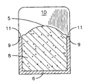
- the surround 1 which is shown as a window surround, essentially frames a window 3 so as to provide an aesthetically-pleasing appearance to the window 3 .
- the surround 1 extends away from the wall 4 of a building and does not, in most cases, extend beyond a window sill 2 .
- a mixture which is typically mortar or stucco, is poured into a channel of the surround grid 6 .
- a person smooths the mortar or stucco so as to remove excess mortar or stucco from the channel using a straight edge.
- the window and/or door surrounds are planar, flush and flat in appearance and a stronger, more durable window and/or door surround is created.
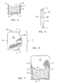
- FIGS. 3 and 4 varying views of a surround created by a first embodiment of a trowel of the present invention are shown.
- the surround 1 may be used to frame an aperture 19 of a building, which may be a door or, as shown in FIG. 3 , a window 3 .
- the surround 1 has a surround face 3 made of a mixture 8 that is placed between grid edges 9 of a channel 7 of a surround grid 6 .
- the surround face 3 created by the first embodiment of a trowel of the present invention is concave so as to add depth to the surround face 5 .
- FIG. 5 a front view of a first embodiment of a trowel of the present invention is shown.
- the trowel 10 is of a predetermined thickness and has a trowel top surface 22 , a trowel bottom surface 23 and a troweling side 24 . Located on each side of the troweling side 24 is a trowel edge 11 .
- FIG. 6 a side view of a first embodiment of a trowel of the present invention is shown.
- the trowel 10 also includes a trowel holding side 21 located opposite of the troweling side 24 on the trowel 10 .
- a trowel profile 12 of a predetermined shape is located on the troweling side 21 and trowel edges 11 are located on each side of the trowel profile 12 .
- the trowel profile 12 is convex so as to create a concave surround face 5 when used as described in relation to FIG. 6 .
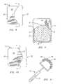
- FIG. 6 shows an upward side view of a first embodiment of the present invention in use.
- a mixture 8 such as mortar or stucco
- the user then allows the mixture 8 to remain in the surround grid 6 for a predetermined amount of time so as to allow the mixture 8 to become shapeable, that is, when the mixture 8 is almost dry.
- the user holds the trowel 10 on the trowel holding side 21 and positions the trowel 10 such that the trowel edges 11 are adjacent to the grid edges 9 wherein the trowel profile 12 is centered within the surround grid 6 .
- the user then drags the trowel 10 along the grid edges 9 so as to remove mixture 8 from the surround grid 6 .
- the mixture 8 in the surround grid 6 dries so as to create a three-dimensional surround 1 as shown in FIG. 2 .
- FIG. 7 shows a side view of a second embodiment of a trowel of the present invention.
- the second embodiment of the trowel 10 of the present invention includes a trowel profile 12 of a predetermined shape and two trowel edges 11 .
- the trowel profile 12 is concave to create a convex surround face 5 when used as described in relation to FIG. 8 .
- FIG. 8 an upward side view of a second embodiment of the present invention in use is shown.
- the second embodiment of the trowel 10 of the present invention is used in the same manner as the first embodiment; that is, the user positions the trowel 10 such that the trowel edges 11 are adjacent to the grid edges 9 wherein the trowel profile 12 is centered within the surround grid 6 and moves the trowel 10 along the surround grid 6 so as to remove a predetermined amount of mixture 8 to create a surround 1 having a convex face 5 .
- FIG. 9 a side view of a third embodiment a trowel of the present invention is shown. Similar to the other embodiments, the third embodiment of the trowel 10 of the present invention includes two trowel edges 11 and a trowel profile 12 of a predetermined shape. However, the predetermined shape of the trowel profile 12 in the third embodiment includes at least one slot 13 which extends from the trowel profile 12 . Thus, when the third embodiment of the trowel 10 of the present invention is used, a surround 1 with a face 5 having at least one line is created.
- FIG. 10 a side plan view of a first embodiment of a roller of the present invention.
- the roller 15 of the present invention includes a handle 17 , an axle 18 of a predetermined shape connected to the handle and head 16 that is rotatable about the axle 18 .
- Located on the head 16 is a predetermined design 20 .
- the user allows the mixture 8 to dry for a predetermined amount of time.
- a user may either use a trowel 10 of the present invention or a convention trowel to remove excess mixture 8 from the surround grid 6 .
- the user places the roller 15 of the present invention within the channel 7 of the surround grid 6 and rolls the head 16 along the surround face 5 .
- a first embodiment of the roller 15 includes an axle 18 having a predetermined convex shape so as to be usable within a concave surround 1 .
- FIG. 11 shows a front perspective view of a window surround 1 created by a roller of the present invention.
- the surround 1 includes a decorative element 14 that is created by using a roller of the present invention.
- FIG. 12 shows a side plan view of a second embodiment of a roller of the present invention.
- the roller 15 of the second embodiment also includes a handle 1 , axle 18 and head 16 having a predetermined design 20 .
- the axle 18 in the second embodiment is linear so as to be used to create a predetermined design 20 on a planar surround 1 .
- FIG. 13 shows a side plan view of a third embodiment of a roller of the present invention.
- the third embodiment also includes a handle 17 , axle 18 and head 16 having a predetermined design 20 ; however, the axle 18 in the third embodiment is concave so as to be usable to create a predetermined surround 20 on a convex surround 1 .
- the use of the present invention will allow a person to quickly and easily create decorative and unique surrounds for windows and doors.
Landscapes
- Engineering & Computer Science (AREA)
- Architecture (AREA)
- Civil Engineering (AREA)
- Structural Engineering (AREA)
- Chemical & Material Sciences (AREA)
- Dispersion Chemistry (AREA)
- Securing Of Glass Panes Or The Like (AREA)
Abstract
Devices for customizing window and/or door surrounds (1) wherein a trowel (10) having a predetermined profile (12) and a roller having predetermined designs (20) are used. The trowel (10) includes a first and second edge (11) and predetermined profile (12) located between the trowel edges (11) for placement of the trowel (10) against edges (9) of a surround grid (6) of a window and/or door surround (1) to create a profile on the surround (1). The profile (12) may be convex, concave or of any other shape. The roller (15) includes a handle (17) and a head (16) wherein the head (16) includes a predetermined design (20) located thereon. By using the devices of the present invention, decorative and distinctive window and/or door surrounds (1) are created.
Description
- This invention relates to devices that customize the appearance of objects, more particularly, a trowel and roller that permit a person to quickly add decorative and aesthetically pleasing elements to window and/or door surrounds.
- Window surrounds, which are also known as plantons and window trims, and door surrounds are popular additions to homes and other buildings as they provide a decorative finish to frame a window or door. Window and/or door surrounds may be made of various materials, such as stucco, concrete, mortar and even foam. The window and/or door surrounds surround the perimeter of a window or door located on a building so as to give a more decorative element to the window and/or door.
- The most popular method of creating window and/or door surrounds is by using foam. The foam is cut at a predetermined length and secured to the building around the window and/or door. However, the use of foam for window and/or door surrounds is problematic as the foam can become easily damaged during strong weather and even from birds, especially woodpeckers which can easily peck holes in the foam. Thus, the popularity of window and/or door surrounds made of mortar or stucco is growing rapidly.
- To create window and/or door surrounds made of mortar or stucco, which are also known as stucco bands, the mortar or stucco is poured into a channel of a grid. When the mortar or stucco is almost dry, a person then smooths the mortar or stucco so as to remove excess mortar or stucco from the channel using a straight edge. Thus, when the mortar or stucco is dry, the window and/or door surrounds are planar, flush and flat in appearance and a stronger, more durable window and/or door surround is created.
- Although the window and/or door surrounds are attractive in appearance as they frame a window and/or door, some property owners prefer to have a more distinctive, unique design to the window and/or door surrounds rather than a plain, flat window and/or door surround.
- Thus, a need exists for devices that permit a person to customize window and/or door surrounds quickly and easily to create a unique design on the window and/or door surround.
- The relevant prior art includes the following references:
-
Patent No. (U.S. unless stated otherwise) Inventor Issue/Publication Date 6,592,668 Rao et al. Jul. 15, 2003 2005/0175781 Schmidt Aug. 11, 2005 2005/0093204 Gregg May 05, 2005 6,994,752 Estrada et al. Feb. 07, 2006 6,206,965 Rao et al. Mar. 27, 2001 4,293,599 Hori et al. Oct. 06, 1981 6,022,588 Wakat Feb. 08, 2000 6,442,912 Phillips et al. Sep. 03, 2002 EP 0 265 961 A1 Barthelt Oct. 30, 1987 - The primary object of the present invention is to provide devices for customizing window and/or door surrounds that are easy to use.
- A further object of the present invention is to provide devices for customizing window and/or door surrounds that are versatile.
- An even further object of the present invention is to provide devices for customizing window and/or door surrounds that are easily transportable.
- Another object of the present invention is to provide devices for customizing window and/or door surrounds that are compact.
- A further object of the present invention is to provide devices for customizing window and/or door surrounds that add decorative elements to window and/or door surrounds quickly.
- The present invention fulfills the above and other objects by providing devices for customizing window and/or door surrounds wherein a trowel having a predetermined profile and a roller having predetermined designs or patterns are used. The trowel includes a first and second edge for placement of the trowel against the grid edges and predetermined profile located between the trowel edges. The profile may be convex, concave or of any other shape. The roller includes a handle and a head wherein the head includes a predetermined design located thereon.
- To use the devices, a person first pours mortar or stucco into a channel of a grid as if creating a traditional window and/or door surround. Then, when the mortar or stucco is almost dry, a user then smooths the mortar or stucco using the trowel of the present invention by placing the profile within the channel with the edges on the grid. Then, the user gently moves the trowel through the channel so as to remove excess mortar or stucco from the channel. Because the trowel of the present invention has a profile that it not straight, a surround having a corresponding shape to the profile is created. In addition, the roller of the present invention may also be used at this time to add a decorative element to the surround. Thus, when the mortar or stucco is dry, the window and/or door surrounds are decorative and distinctive from the traditional, plain, flat surrounds currently created in the prior art.
- The above and other objects, features and advantages of the present invention should become even more readily apparent to those skilled in the art upon a reading of the following detailed description in conjunction with the drawings wherein there is shown and described illustrative embodiments of the invention.
- In the following detailed description, reference will be made to the attached drawings in which:
-
FIG. 1 is a frontal view of a surround of the prior art; -
FIG. 2 is a side view of the embodiment ofFIG. 1 ; -
FIG. 3 is a front perspective of a surround created by a first embodiment of a trowel of the present invention; -
FIG. 4 is a cross-sectional view along line 4-4 of the embodiment ofFIG. 3 ; -
FIG. 5 is a front view of a first embodiment of a trowel of the present invention; -
FIG. 6 is a side view of a first embodiment of a trowel of the present invention; -
FIG. 7 is an upward side view of a first embodiment of the trowel of the present invention in use; -
FIG. 8 is a side view of a second embodiment of a trowel of the present invention; -
FIG. 9 is an upward side view of a second embodiment of the trowel of the present invention in use; -
FIG. 10 is a side view of a third embodiment of a trowel of the present invention; -
FIG. 11 is a side plan view of a first embodiment of a roller of the present invention; -
FIG. 12 is a front perspective view of a surround created by a roller of the present invention; -
FIG. 13 is a side plan view of a second embodiment of a roller of the present invention; and -
FIG. 14 is a side plan view of a third embodiment of a roller of the present invention. - For purposes of describing the preferred embodiment, the terminology used in reference to the numbered components in the drawings is as follows:
-
1. surround, generally 2. window sill 3. window 4. wall 5. surround face 6. surround grid 7. channel 8. mixture 9. grid edge 10. trowel 11. trowel edge 12. trowel profile 13. slot 14. decorative element 15. roller 16. head 17. handle 18. axle 19. aperture 20. design 21. trowel holding side 22. trowel top surface 23. trowel bottom surface 24. troweling side - With reference to
FIGS. 1 and 2 , varying views of a surround of the prior art is shown. Thesurround 1, which is shown as a window surround, essentially frames awindow 3 so as to provide an aesthetically-pleasing appearance to thewindow 3. Thesurround 1 extends away from thewall 4 of a building and does not, in most cases, extend beyond awindow sill 2. To create thesurround 1, a mixture, which is typically mortar or stucco, is poured into a channel of thesurround grid 6. When the mortar or stucco is almost dry, a person then smooths the mortar or stucco so as to remove excess mortar or stucco from the channel using a straight edge. Thus, when the mortar or stucco is dry, the window and/or door surrounds are planar, flush and flat in appearance and a stronger, more durable window and/or door surround is created. - In
FIGS. 3 and 4 , varying views of a surround created by a first embodiment of a trowel of the present invention are shown. Thesurround 1 may be used to frame anaperture 19 of a building, which may be a door or, as shown inFIG. 3 , awindow 3. Thesurround 1 has asurround face 3 made of amixture 8 that is placed betweengrid edges 9 of achannel 7 of asurround grid 6. Thesurround face 3 created by the first embodiment of a trowel of the present invention is concave so as to add depth to thesurround face 5. - In
FIG. 5 , a front view of a first embodiment of a trowel of the present invention is shown. Thetrowel 10 is of a predetermined thickness and has a troweltop surface 22, atrowel bottom surface 23 and a trowelingside 24. Located on each side of the trowelingside 24 is atrowel edge 11. - In
FIG. 6 , a side view of a first embodiment of a trowel of the present invention is shown. Thetrowel 10 also includes atrowel holding side 21 located opposite of the trowelingside 24 on thetrowel 10. Atrowel profile 12 of a predetermined shape is located on the trowelingside 21 and trowel edges 11 are located on each side of thetrowel profile 12. In the first embodiment, thetrowel profile 12 is convex so as to create aconcave surround face 5 when used as described in relation toFIG. 6 . -
FIG. 6 shows an upward side view of a first embodiment of the present invention in use. To use thetrowel 10 of the present invention to create a profiledface 5 for asurround 1, amixture 8, such as mortar or stucco, is poured into thechannel 7 of asurround grid 6 wherein thesurround grid 6 has grid edges 9. The user then allows themixture 8 to remain in thesurround grid 6 for a predetermined amount of time so as to allow themixture 8 to become shapeable, that is, when themixture 8 is almost dry. Then, the user holds thetrowel 10 on thetrowel holding side 21 and positions thetrowel 10 such that the trowel edges 11 are adjacent to the grid edges 9 wherein thetrowel profile 12 is centered within thesurround grid 6. The user then drags thetrowel 10 along the grid edges 9 so as to removemixture 8 from thesurround grid 6. When the user has completed this task, themixture 8 in thesurround grid 6 dries so as to create a three-dimensional surround 1 as shown inFIG. 2 . - Next,
FIG. 7 shows a side view of a second embodiment of a trowel of the present invention. Similar to the first embodiment, the second embodiment of thetrowel 10 of the present invention includes atrowel profile 12 of a predetermined shape and two trowel edges 11. In this second embodiment, however, thetrowel profile 12 is concave to create aconvex surround face 5 when used as described in relation toFIG. 8 . - With reference to
FIG. 8 , an upward side view of a second embodiment of the present invention in use is shown. The second embodiment of thetrowel 10 of the present invention is used in the same manner as the first embodiment; that is, the user positions thetrowel 10 such that the trowel edges 11 are adjacent to the grid edges 9 wherein thetrowel profile 12 is centered within thesurround grid 6 and moves thetrowel 10 along thesurround grid 6 so as to remove a predetermined amount ofmixture 8 to create asurround 1 having aconvex face 5. - In
FIG. 9 , a side view of a third embodiment a trowel of the present invention is shown. Similar to the other embodiments, the third embodiment of thetrowel 10 of the present invention includes twotrowel edges 11 and atrowel profile 12 of a predetermined shape. However, the predetermined shape of thetrowel profile 12 in the third embodiment includes at least oneslot 13 which extends from thetrowel profile 12. Thus, when the third embodiment of thetrowel 10 of the present invention is used, asurround 1 with aface 5 having at least one line is created. - In
FIG. 10 , a side plan view of a first embodiment of a roller of the present invention. Theroller 15 of the present invention includes ahandle 17, anaxle 18 of a predetermined shape connected to the handle andhead 16 that is rotatable about theaxle 18. Located on thehead 16 is apredetermined design 20. To use, the user allows themixture 8 to dry for a predetermined amount of time. Then, a user may either use atrowel 10 of the present invention or a convention trowel to removeexcess mixture 8 from thesurround grid 6. Finally, the user places theroller 15 of the present invention within thechannel 7 of thesurround grid 6 and rolls thehead 16 along thesurround face 5. By doing so, thedesign 20 on thehead 16 imprints apredetermined design 20 onto thesurround face 5 so as to create adecorative element 14. A first embodiment of theroller 15 includes anaxle 18 having a predetermined convex shape so as to be usable within aconcave surround 1. -
FIG. 11 shows a front perspective view of awindow surround 1 created by a roller of the present invention. Thesurround 1 includes adecorative element 14 that is created by using a roller of the present invention. -
FIG. 12 shows a side plan view of a second embodiment of a roller of the present invention. Theroller 15 of the second embodiment also includes ahandle 1,axle 18 andhead 16 having apredetermined design 20. However, theaxle 18 in the second embodiment is linear so as to be used to create apredetermined design 20 on aplanar surround 1. - Finally,
FIG. 13 shows a side plan view of a third embodiment of a roller of the present invention. The third embodiment also includes ahandle 17,axle 18 andhead 16 having apredetermined design 20; however, theaxle 18 in the third embodiment is concave so as to be usable to create apredetermined surround 20 on aconvex surround 1. - The use of the present invention will allow a person to quickly and easily create decorative and unique surrounds for windows and doors.
- It is to be understood that while a preferred embodiment of the invention is illustrated, it is not to be limited to the specific form or arrangement of parts herein described and shown. It will be apparent to those skilled in the art that various changes may be made without departing from the scope of the invention and the invention is not be considered limited to what is shown and described in the specification and drawings.
Claims (16)
1. A device for customizing window and/or door surrounds comprising:
a trowel having a top surface, a bottom surface, a trowel holding side and a troweling side;
said trowel holding side is located opposite of said troweling side on said trowel;
a predetermined profile located on said troweling side; and
at least one edge located on each side of said predetermined profile.
2. The device for customizing window and/or door surrounds of claim 1 wherein:
said predetermined profile is convex.
3. The device for customizing window and/or door surrounds of claim 1 wherein:
said predetermined profile is concave.
4. The device for customizing window and/or door surrounds of claim 1 further comprising:
at least one slot extending from said profile.
5. The device for customizing window and/or door surrounds of claim 2 further comprising:
at least one slot extending from said profile.
6. The device for customizing window and/or door surrounds of claim 3 further comprising:
at least one slot extending from said profile.
7. A device for customizing window and/or door surrounds comprising:
a roller having a handle;
an axle connected to said handle; and
a head rotatable about said axle wherein said head has a predetermined design located thereon.
8. The device for customizing window and/or door surrounds of claim 7 wherein:
said axle is convex.
9. The device for customizing window and/or door surrounds of claim 7 wherein:
said axle is concave.
10. The device for customizing window and/or door surrounds of claim 7 wherein:
said axle is linear.
11. A method for using a device for customizing window and/or door surrounds comprising a trowel having a top surface, a bottom surface, a trowel holding side and a troweling side, said trowel holding side is located opposite to said troweling side, a predetermined profile located on said troweling side; and at least one edge located on each side of said predetermined profile, said method comprising steps of:
a. pouring a mixture into a grid having two grid edges and a channel located between the two grid edges;
b. allowing said mixture to dry for a predetermined amount of time;
c. placing said profile within said channel;
d. placing said at least one edge of said trowel against said grid edges; and
e. moving said trowel along said grid so as to remove a predetermined amount of said mixture.
12. The method of claim 11 wherein:
said profile is convex.
14. The method of claim 11 wherein:
said profile is concave.
15. The method of claim 12 further comprising:
at least one slot extending from said profile.
16. The method of claim 13 further comprising:
at least one slot extending from said profile.
17. The truss spacing device of claim 11 further comprising the additional steps of:
f. placing a roller having a handle, an axle connected to said handle and a head rotatable about said axle wherein said head has a predetermined design located thereon within said channel; and
g. rolling said roller along said mixture so as to imprint said predetermined design on said mixture.
Priority Applications (1)
| Application Number | Priority Date | Filing Date | Title |
|---|---|---|---|
| US11/591,622 US20080098688A1 (en) | 2006-10-31 | 2006-10-31 | Devices for customizing window and door surrounds and method |
Applications Claiming Priority (1)
| Application Number | Priority Date | Filing Date | Title |
|---|---|---|---|
| US11/591,622 US20080098688A1 (en) | 2006-10-31 | 2006-10-31 | Devices for customizing window and door surrounds and method |
Publications (1)
| Publication Number | Publication Date |
|---|---|
| US20080098688A1 true US20080098688A1 (en) | 2008-05-01 |
Family
ID=39328485
Family Applications (1)
| Application Number | Title | Priority Date | Filing Date |
|---|---|---|---|
| US11/591,622 Abandoned US20080098688A1 (en) | 2006-10-31 | 2006-10-31 | Devices for customizing window and door surrounds and method |
Country Status (1)
| Country | Link |
|---|---|
| US (1) | US20080098688A1 (en) |
Citations (19)
| Publication number | Priority date | Publication date | Assignee | Title |
|---|---|---|---|---|
| US1490220A (en) * | 1922-04-05 | 1924-04-15 | William C Lawrence | Bricklayer's trowel |
| US1617125A (en) * | 1926-06-03 | 1927-02-08 | Kuhar George | Plumb trowel |
| US1868013A (en) * | 1930-08-28 | 1932-07-19 | David R Humphreys | Wall texture smoothing trowel |
| US4293599A (en) * | 1974-10-29 | 1981-10-06 | Nippon Paint Co., Ltd. | Method of forming decorative relief pattern and pattern-forming device therefor |
| US4915610A (en) * | 1988-09-06 | 1990-04-10 | Curry Emory H | Joint finishing tool |
| US5479675A (en) * | 1995-03-01 | 1996-01-02 | Pytlewski; Walter W. | Hand trowel assembly |
| US5547240A (en) * | 1995-01-06 | 1996-08-20 | Hartshorn; Gordon K. | Hand-held trowel with an accessible hollow handle compartment |
| US5997270A (en) * | 1997-05-15 | 1999-12-07 | Labonte; Hubert | Automated trowel |
| US6022588A (en) * | 1996-05-30 | 2000-02-08 | Wagner Spray Tech Corporation | Method for painting with hand tool having bifurcated roller portions |
| US6206965B1 (en) * | 1997-10-02 | 2001-03-27 | Angelo Rao | Apparatus for coating a decorative workpiece |
| US6205610B1 (en) * | 1997-06-04 | 2001-03-27 | Lee Anthony Westthorp | Adhesive trowel |
| US6393650B1 (en) * | 2001-01-30 | 2002-05-28 | David Nicholas Gerakos | Margin trowel with bucket hook |
| US6442912B1 (en) * | 1997-12-03 | 2002-09-03 | Innovative Coatings Corporation | Method for retrofitting a surface of a house or building |
| US6592668B2 (en) * | 1997-10-02 | 2003-07-15 | Angelo Rao | Apparatus for coating a decorative workpiece |
| US6880198B1 (en) * | 1992-05-08 | 2005-04-19 | David F. Hazard | Adjoining surface device for working viscous materials |
| US20050093204A1 (en) * | 2003-11-05 | 2005-05-05 | Gregg David W. | Stamping apparatus |
| US20050097697A1 (en) * | 2002-10-10 | 2005-05-12 | Mario Nistico | Moon trowel |
| US20050175781A1 (en) * | 2004-02-05 | 2005-08-11 | David Schmidt | Method and apparatus to produce decorative mouldings |
| US6994752B2 (en) * | 2003-06-17 | 2006-02-07 | Coraza Industrial, S.A. De C.V. | Method and apparatus for manufacturing decorative moldings |
-
2006
- 2006-10-31 US US11/591,622 patent/US20080098688A1/en not_active Abandoned
Patent Citations (19)
| Publication number | Priority date | Publication date | Assignee | Title |
|---|---|---|---|---|
| US1490220A (en) * | 1922-04-05 | 1924-04-15 | William C Lawrence | Bricklayer's trowel |
| US1617125A (en) * | 1926-06-03 | 1927-02-08 | Kuhar George | Plumb trowel |
| US1868013A (en) * | 1930-08-28 | 1932-07-19 | David R Humphreys | Wall texture smoothing trowel |
| US4293599A (en) * | 1974-10-29 | 1981-10-06 | Nippon Paint Co., Ltd. | Method of forming decorative relief pattern and pattern-forming device therefor |
| US4915610A (en) * | 1988-09-06 | 1990-04-10 | Curry Emory H | Joint finishing tool |
| US6880198B1 (en) * | 1992-05-08 | 2005-04-19 | David F. Hazard | Adjoining surface device for working viscous materials |
| US5547240A (en) * | 1995-01-06 | 1996-08-20 | Hartshorn; Gordon K. | Hand-held trowel with an accessible hollow handle compartment |
| US5479675A (en) * | 1995-03-01 | 1996-01-02 | Pytlewski; Walter W. | Hand trowel assembly |
| US6022588A (en) * | 1996-05-30 | 2000-02-08 | Wagner Spray Tech Corporation | Method for painting with hand tool having bifurcated roller portions |
| US5997270A (en) * | 1997-05-15 | 1999-12-07 | Labonte; Hubert | Automated trowel |
| US6205610B1 (en) * | 1997-06-04 | 2001-03-27 | Lee Anthony Westthorp | Adhesive trowel |
| US6206965B1 (en) * | 1997-10-02 | 2001-03-27 | Angelo Rao | Apparatus for coating a decorative workpiece |
| US6592668B2 (en) * | 1997-10-02 | 2003-07-15 | Angelo Rao | Apparatus for coating a decorative workpiece |
| US6442912B1 (en) * | 1997-12-03 | 2002-09-03 | Innovative Coatings Corporation | Method for retrofitting a surface of a house or building |
| US6393650B1 (en) * | 2001-01-30 | 2002-05-28 | David Nicholas Gerakos | Margin trowel with bucket hook |
| US20050097697A1 (en) * | 2002-10-10 | 2005-05-12 | Mario Nistico | Moon trowel |
| US6994752B2 (en) * | 2003-06-17 | 2006-02-07 | Coraza Industrial, S.A. De C.V. | Method and apparatus for manufacturing decorative moldings |
| US20050093204A1 (en) * | 2003-11-05 | 2005-05-05 | Gregg David W. | Stamping apparatus |
| US20050175781A1 (en) * | 2004-02-05 | 2005-08-11 | David Schmidt | Method and apparatus to produce decorative mouldings |
Similar Documents
| Publication | Publication Date | Title |
|---|---|---|
| CA2271496C (en) | System and method for attaching architectural moldings and insulation sheets to buildings | |
| US1976947A (en) | Wall veneer | |
| US20080098688A1 (en) | Devices for customizing window and door surrounds and method | |
| CN204616679U (en) | A kind of spliced Pet house | |
| DE19637836A1 (en) | Window frame element, for the manufacture of window frames | |
| CN206591775U (en) | Door leaf closes up with carpet, stone material and constructed at doorway | |
| JP5793584B2 (en) | Brace penetration cutout cover and window frame | |
| DE3909245A1 (en) | Process for producing a roller-blind casing | |
| CN211923667U (en) | Sauna room | |
| JP3981543B2 (en) | Window storage structure | |
| DE102004025862A1 (en) | Weather strip for window frames and door frames comprises a plaster region, an inserting region for positioning the weather strip on a window frame or door frame and a fixing region which is integral with the plaster region | |
| JP2571618Y2 (en) | Window surrounding edge member | |
| US7353617B1 (en) | Surface template | |
| CN107503639A (en) | A kind of height-adjustable Combined wooden door | |
| KR20120074439A (en) | Traditional construction methods of the structure floor | |
| KR200296029Y1 (en) | Decoration block for the construction | |
| KR200180770Y1 (en) | Finishing device for constructing sash frame | |
| KR20050040284A (en) | The transformation-type door frame to possibility settling of a dispute | |
| CN104929494A (en) | Imitated solid wood aluminum alloy door and installing method thereof | |
| JPH0314507Y2 (en) | ||
| JPH0545755Y2 (en) | ||
| CN203769541U (en) | Assembled steel door frame with replaceable inside decorative buckling edges and outer decorative buckling edges | |
| DE19502531A1 (en) | Decorative panel for humid buildings, especially indoor swimming pools | |
| JPS6133778Y2 (en) | ||
| KR20090123354A (en) | Exterior panel of building |
Legal Events
| Date | Code | Title | Description |
|---|---|---|---|
| STCB | Information on status: application discontinuation |
Free format text: ABANDONED -- FAILURE TO RESPOND TO AN OFFICE ACTION |