US20080098671A1 - Shock suppressor - Google Patents
Shock suppressor Download PDFInfo
- Publication number
- US20080098671A1 US20080098671A1 US11/925,205 US92520507A US2008098671A1 US 20080098671 A1 US20080098671 A1 US 20080098671A1 US 92520507 A US92520507 A US 92520507A US 2008098671 A1 US2008098671 A1 US 2008098671A1
- Authority
- US
- United States
- Prior art keywords
- base
- slider
- connecting device
- holder
- shock suppressor
- Prior art date
- Legal status (The legal status is an assumption and is not a legal conclusion. Google has not performed a legal analysis and makes no representation as to the accuracy of the status listed.)
- Abandoned
Links
- 230000035939 shock Effects 0.000 title claims abstract description 89
- 230000007246 mechanism Effects 0.000 claims abstract description 14
- 238000013016 damping Methods 0.000 claims description 11
- 230000008093 supporting effect Effects 0.000 claims description 11
- 230000033001 locomotion Effects 0.000 description 4
- 238000004519 manufacturing process Methods 0.000 description 3
- 239000000463 material Substances 0.000 description 3
- 238000006073 displacement reaction Methods 0.000 description 2
- 230000000694 effects Effects 0.000 description 2
- 238000010276 construction Methods 0.000 description 1
- 239000003190 viscoelastic substance Substances 0.000 description 1
Images


Classifications
-
- E—FIXED CONSTRUCTIONS
- E04—BUILDING
- E04H—BUILDINGS OR LIKE STRUCTURES FOR PARTICULAR PURPOSES; SWIMMING OR SPLASH BATHS OR POOLS; MASTS; FENCING; TENTS OR CANOPIES, IN GENERAL
- E04H9/00—Buildings, groups of buildings or shelters adapted to withstand or provide protection against abnormal external influences, e.g. war-like action, earthquake or extreme climate
- E04H9/02—Buildings, groups of buildings or shelters adapted to withstand or provide protection against abnormal external influences, e.g. war-like action, earthquake or extreme climate withstanding earthquake or sinking of ground
- E04H9/021—Bearing, supporting or connecting constructions specially adapted for such buildings
- E04H9/023—Bearing, supporting or connecting constructions specially adapted for such buildings and comprising rolling elements, e.g. balls, pins
Definitions
- the present invention relates to a shock suppressor for a building, a bridge or a motion sensitive equipment, and more particularly to a shock suppressor that can dissipate seismic shock energy in both horizontal and vertical directions efficiently.
- a conventional shock suppressor is provided to dissipate shock energy and substantially comprises a base, a supporting plate and a slider.
- the base and the supporting plate have respectively a recess corresponding to each other, and the slider are held slidably in the recesses in the base and the supporting plate.
- the slider comprises a first sliding block, a second sliding block and a ball.
- Each sliding block has a convex end corresponding to a corresponding recess and a concavity for holding the ball inside.
- the conventional shock suppressor can dissipate shock energy in multiple directions, but has a complicate structure.
- to define semispherical recesses in both the base and the supporting plate is difficult and time-consuming, and the cost for manufacturing the conventional shock suppressor is high.
- the conventional shock suppressor cannot be economically applied to bridges or an elongated building because that the dissipating frequencies and displacement capacities in different shock-dissipating directions of the conventional shock suppressor are the same.
- the present invention tends to provide a shock suppressor to mitigate or obviate the aforementioned problems.
- the main objective of the invention is to provide a shock suppressor that can dissipate seismic shock energy in both horizontal and vertical directions efficiently.
- the shock suppressor has a first base, a second base, a sliding holder assembly and a connecting device.
- the second base is parallel to the first base.
- the connecting device is slidably mounted between the first base and second base to connect the first and second bases.
- the first base abuts against the connecting device in a curved contact surface to provide a first sliding mechanism in multiple directions.
- the second base abuts against the connecting device to provide a second sliding mechanism in a unidirection.
- the sliding holder assembly is mounted between the connecting device and at least one of the bases in a universal contacting manner.
- FIG. 1 is an exploded perspective view in partial cross section of a first embodiment of a shock suppressor in accordance with the present invention
- FIG. 2 is an exploded perspective view in partial cross section of a second embodiment of a shock suppressor in accordance with the present invention
- FIG. 3 is an exploded perspective view in partial cross section of a third embodiment of a shock suppressor in accordance with the present invention.
- FIG. 4 is a perspective view in partial cross section of a fourth embodiment of a shock suppressor in accordance with the present invention.
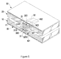
- FIG. 5 is a perspective view in partial cross section of a fifth embodiment of a shock suppressor in accordance with the present invention.
- FIG. 6 is a perspective view in partial cross section of a sixth embodiment of a shock suppressor in accordance with the present invention.
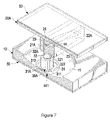
- FIG. 7 is a perspective view in partial cross section of a seventh embodiment of a shock suppressor in accordance with the present invention.
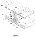
- FIG. 8 is a perspective view in partial cross section of an eighth embodiment of a shock suppressor in accordance with the present invention.
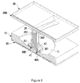
- FIG. 9 is a perspective view in partial cross section of a ninth embodiment of a shock suppressor in accordance with the present invention.
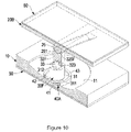
- FIG. 10 is a perspective view in partial cross section of a tenth embodiment of a shock suppressor in accordance with the present invention.
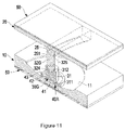
- FIG. 11 is a perspective view in partial cross section of an eleventh embodiment of a shock suppressor in accordance with the present invention.
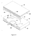
- FIG. 12 is an exploded perspective view in partial cross section of a twelfth embodiment of a shock suppressor in accordance with the present invention.
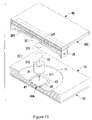
- FIG. 13 is an exploded perspective view in partial cross section of a thirteenth embodiment of a shock suppressor in accordance with the present invention.
- FIG. 14 is an exploded perspective view in partial cross section of a fourteenth embodiment of a shock suppressor in accordance with the present invention.
- FIG. 15 is a side view in partial cross section of a fifteenth embodiment of a shock suppressor in accordance with the present invention.
- FIG. 16 is a side view in partial cross section of a sixteenth embodiment of a shock suppressor in accordance with the present invention.
- FIG. 17 is a side view in partial cross section of a seventeenth embodiment of a shock suppressor in accordance with the present invention.
- a shock suppressor in accordance with the present invention can be applied to a building, a bridge or an instrument and comprises a first base ( 10 ), a second base ( 20 ), a sliding holder assembly ( 40 ) and a connecting device ( 30 ).
- the second base ( 20 ) is parallel to the first base ( 10 ).
- the connecting device ( 30 ) is slidably mounted between the first base ( 10 ) and second base ( 20 ) to connect the first and second bases ( 10 , 20 ).
- the first base ( 10 ) is connected with the connecting device ( 30 ) in curved contact surfaces to provide a first sliding mechanism in multiple directions.
- the second base ( 20 ) is connected with the connecting device ( 30 ) to provide a second sliding mechanism in a unidirection.
- the sliding holder assembly ( 40 ) is mounted between the connecting device ( 30 ) and at least one of the bases ( 10 , 20 ) in a universal contacting manner.
- a damping device ( 50 ) is mounted on at least one of the first base ( 10 ) and the second base ( 20 ).
- the damping device ( 50 ) can be made of resilient rubber material, viscoelastic material, frictional material or material with an excellent damping coefficient.
- first and second bases ( 10 , 20 ) can be exchanged based on different needs.
- the first base ( 10 ) can be mounted on the ground, the floor or a building and is located below the second base ( 20 ).
- the second base ( 20 ) can be mounted on the ground, the floor or a building and is located below the first base ( 10 ).
- the first base ( 10 ) has a concave surface ( 11 ) defined in a side facing the second base ( 20 ).
- the second base ( 20 ) has an elongated sliding channel ( 21 ) defined in a side facing the first base ( 10 ), and the sliding channel ( 21 ) has a concave surface ( 22 ) facing the first base ( 10 ).
- the damping device ( 50 ) comprises two damping pads attached respectively to the first and second bases ( 10 , 20 ).
- the sliding holder assembly ( 40 ) comprises a first holder ( 401 ) and a second holder ( 402 ).
- the first holder ( 401 ) is slidably in the concave surface ( 11 ) in the first base ( 10 ) has a convex bottom ( 41 ) abutting and matching with the concave surface ( 11 ) in the first base ( 10 ).
- a recess ( 42 ) with a concave bottom is defined in the first holder ( 401 ) at a side facing the second base ( 20 ) and the second holder ( 402 ) to form an annular wall ( 43 ) around the first holder ( 401 ).
- the recess ( 42 ) in the first holder ( 401 ) has a diameter larger than that of the connecting device ( 30 ).
- the second holder ( 402 ) is held slidably in sliding channel ( 21 ) in the second base ( 20 ) and has a convex bottom ( 44 ) abutting and matching with the concave surface ( 22 ) in the sliding channel ( 21 ).
- a recess ( 45 ) with a concave bottom is defined in the second holder ( 402 ) at a side facing the first holder ( 401 ) to form two limiting flanges ( 46 ) respectively at two ends of the second holder ( 402 ).
- the connecting device ( 30 ) may be cylindrical rod having two convex ends ( 301 , 302 ) abutting and matching respectively with the concave bottoms of the recesses ( 42 , 45 ) in the holders ( 401 , 402 ).
- the connecting device ( 30 ) further has two guiding sides respectively abutting against the inner sides of the sliding channel ( 21 ).
- the first sliding mechanism between the first base ( 10 ) and the connecting device ( 30 ) in a curved contact surface is achieved.
- the second sliding mechanism between the second base ( 20 ) and the connecting device ( 30 ) in a unidirectional sliding direction is achieved.
- the connecting device ( 30 ) can provide an excellent supporting effect to the supported structures including buildings, bridges, etc. before a shock occurring.
- the first base ( 10 ) will move relative to the second base ( 20 ).
- the shock energy can be efficiently dissipated, eliminated, suppressed or absorbed in both horizontal and vertical directions.
- the first and second bases ( 10 , 20 ) When the shock has stopped, the first and second bases ( 10 , 20 ) will automatically move to an original position with the concave and convex surfaces in the bases ( 10 , 12 ), the holders ( 401 , 402 ) and the connecting device ( 30 ), such that the shock suppressor has an automatic positioning effect to an original status.
- the movement of the bases ( 10 , 20 ) to the original position is quick and stable.
- the connecting device ( 30 A) comprises a first slider ( 31 ), a second slider ( 32 ) and a universal connector.
- the first slider ( 31 ) has a facing end facing to the second slider ( 32 ) and a convex end ( 311 ) formed on the first slider ( 31 ) at an end opposite to the facing end and abutting and matching with the concave bottom of the recess ( 42 ) in the first holder ( 401 ).
- the second slider ( 32 ) has a facing end facing to the first slider ( 31 ) and a convex end ( 322 ) formed on the second slider ( 32 ) at an end opposite to the facing end and abutting and matching with the concave bottom of the recess ( 45 ) in the second holder ( 402 ).
- the second slider ( 32 ) further has two guiding sides ( 321 ) respectively abutting against the inner sides of the sliding channel ( 21 ).
- the universal connector is mounted between the first slider ( 31 ) and the second slider ( 32 ) and comprises two recesses ( 312 , 323 ) and a supporting member ( 33 ).
- the recesses ( 312 , 323 ) are defined respectively in the facing ends of the first slider ( 31 ) and the second slider ( 32 ).
- the supporting member ( 33 ) is rotatably mounted in the recesses ( 312 , 323 ) in the first and second sliders ( 31 , 32 ).
- the recesses ( 312 , 323 ) in the first and second sliders ( 31 , 32 ) are hemispherical, and the supporting member ( 33 ) is spherical.
- the third embodiment of the shock suppressor has a structure substantially same as that in the second embodiment except that the universal connector of the connecting device ( 30 B) comprises a recess ( 312 ) defined in the facing end of the first slider ( 31 ) and a convex protrusion ( 324 ) formed on the facing end of the second slider ( 32 B) and rotatably held in the recess ( 312 ) in the first slider ( 31 ).
- the recess ( 312 ) in the first slider ( 31 ) and the convex protrusion ( 324 ) on the second slider ( 32 B) are hemispherical.
- the fourth embodiment of the shock suppressor has a structure substantially same as that in the second embodiment except that the universal connector of the connecting device ( 30 C) comprises a recess ( 323 ) defined in the facing end of the second slider ( 32 C) and a convex surface ( 313 ) formed on the facing end of the first slider ( 31 C) and rotatably held in the recess ( 323 ) in the second slider ( 32 C).
- the universal connector of the connecting device ( 30 C) comprises a recess ( 323 ) defined in the facing end of the second slider ( 32 C) and a convex surface ( 313 ) formed on the facing end of the first slider ( 31 C) and rotatably held in the recess ( 323 ) in the second slider ( 32 C).
- the recess ( 323 ) in the second slider ( 32 C) is hemispherical, and the first slider ( 31 C) is a hemispherical block with a hemispherical convex surface ( 313 ) rotatably held in the recess ( 323 ) in the second slider ( 32 C).
- the first slider ( 31 D) of the connecting device ( 30 D) is a flat round block
- the recess ( 323 D) in the second slider ( 32 D) is a flat concave recess
- the convex surface ( 313 D) on the first slider ( 31 D) is a flat convex surface.
- the second base ( 20 A) has two parallel side plates ( 23 ) formed on and extending from the side facing the first base ( 10 ) and a guiding block ( 24 ) mounted between the side plates ( 23 ) to define the sliding channel ( 21 A) between the side plates ( 23 ) and the guiding block ( 24 ).
- the guiding block ( 24 ) has a concave surface ( 22 A) facing the first base ( 10 ) and corresponding to and matching with the convex bottom ( 44 ) on the second holder ( 402 ).
- the connecting device ( 30 A) has a first slider ( 31 A), a second slider ( 32 A) and a universal connector with same structures as that in the second embodiment.
- the universal connector of the connecting device ( 30 B) comprises a hemispherical recess ( 312 ) defined in the facing end of the first slider ( 31 ) and a hemispherical convex protrusion ( 324 ) formed on the facing end of the second slider ( 32 B) and rotatably held in the recess ( 312 ) in the first slider ( 31 ).
- the second base ( 20 B) has a rail ( 25 ) attached to the side facing the first base ( 10 ).
- the rail ( 25 ) has a curved rib ( 251 ) with a concave surface facing the first base ( 10 ).
- the connecting device ( 30 E) has an engaging channel ( 303 ) corresponding to and matching with the curved rib ( 251 ) on the rail ( 25 ).
- the curved rib ( 251 ) of the rail ( 25 ) on the second base ( 20 B) and the engaging channel ( 303 ) in the connecting device ( 30 E) may have a V-shaped cross section, a semispherical cross section or an inverse T-shaped cross section as shown in FIG. 12 . Accordingly, the second sliding mechanism in a unidirectional sliding direction is constructed of the rib ( 251 ) and the engaging channel ( 303 ) and the sliding holder assembly ( 40 A) is without the second holder.
- the second slider ( 32 F) of the connecting device ( 30 F) has an engaging channel ( 325 F) corresponding to and matching with the curved rib ( 251 ) on the rail ( 25 ).
- the eleventh embodiment of the shock suppressor has a structure substantially same as that in the tenth embodiment except that the universal connector of the connecting device ( 30 G) comprises a hemispherical recess ( 312 ) defined in the facing end of the first slider ( 31 ) and a hemispherical convex protrusion ( 324 ) formed on the facing end of the second slider ( 32 G) and rotatably held in the recess ( 312 ) in the first slider ( 31 ).
- the rib ( 261 ) of the rail ( 26 ) on the second base ( 20 C) and the engaging channel ( 325 ) in the connecting device ( 30 H) have an inverse T-shaped cross section.
- the rib ( 261 ) of the rail ( 26 ) on the second base ( 20 C) and the engaging channel ( 326 ) in the second slider ( 321 ) of the connecting device ( 30 I) have an inverse T-shaped cross section.
- the fourteenth embodiment of the shock suppressor has a structure substantially same as that in the thirteenth embodiment except that the universal connector of the connecting device ( 30 J) comprises a hemispherical recess ( 312 ) defined in the facing end of the first slider ( 31 ) and a hemispherical convex protrusion ( 324 ) formed on the facing end of the second slider ( 323 ) and rotatably held in the recess ( 312 ) in the first slider ( 31 ).
- the rail ( 27 ) on the second base ( 20 D) further has a flat and unidirectional rib ( 271 ) matching and engaging with an engaging channel ( 304 ) defined in the connecting device ( 30 K), and the sliding holder assembly ( 40 A) is without the second holder.
- the rail ( 27 ) further has a bar extending through the connecting device ( 30 K) and two resilient members ( 272 ) mounted around the bar and abutting against the connecting device ( 30 K).
- the resilient members ( 272 ) may be springs, plastic sleeves or cylinders. With the arrangement of the resilient members ( 272 ), the resilient members ( 272 ) can provide a recoil force to the connecting device ( 30 K) to make the connecting device ( 30 K) to move automatically to the original status.
- the second holder ( 32 L) of the connecting device ( 30 L) has an engaging channel ( 304 ) engaging with the flat and unidirectional rib ( 271 ) of the rail ( 27 ) on the second base ( 20 D).
- the bar of the rail ( 27 ) extends through the second slider ( 32 L), and the resilient members ( 272 ) abuts against the second slider ( 32 L).
- the seventeenth embodiment of the shock suppressor has a structure substantially same as that in the sixteenth embodiment except that the universal connector of the connecting device ( 30 M) comprises a hemispherical recess ( 312 ) defined in the facing end of the first slider ( 31 ) and a hemispherical convex protrusion ( 324 ) formed on the facing end of the second slider ( 32 M) and rotatably held in the recess ( 312 ) in the first slider ( 31 ).
- shock energy in multiple directions can be efficiently dissipated by the shock suppressor in accordance with the present invention.
- the first sliding mechanism in a universal direction and the second sliding mechanism in a unidirectional sliding direction the displacement capacities and shock-dissipating frequencies in different direction are different. Therefore, the shock suppressor can be applied to bridges or elongated building and is versatile in use.
- the shock suppressor has a simplified structure, such that to manufacture and assemble the shock suppressor is easy and convenient and the cost for manufacturing the shock suppressor can be reduced.
Landscapes
- Engineering & Computer Science (AREA)
- Architecture (AREA)
- Business, Economics & Management (AREA)
- Emergency Management (AREA)
- Environmental & Geological Engineering (AREA)
- Civil Engineering (AREA)
- Structural Engineering (AREA)
- Vibration Prevention Devices (AREA)
Abstract
A shock suppressor has a first base, a second base, a sliding holder assembly and a connecting device. The second base is parallel to the first base. The connecting device is slidably mounted between the first base and second base to connect the first and second bases. The first base abuts against the connecting device in a curved contact surface to provide a first sliding mechanism in multiple directions. The second base abuts against the connecting device to provide a second sliding mechanism in a unidirection. The sliding holder assembly is mounted between the connecting device and at least one of the bases in a universal contacting manner.
Description
- This application claims priority to Taiwanese Patent Application Serial Number 095140216 filed Oct. 31, 2006, the entire content of which is incorporated herein by reference.
- The present invention relates to a shock suppressor for a building, a bridge or a motion sensitive equipment, and more particularly to a shock suppressor that can dissipate seismic shock energy in both horizontal and vertical directions efficiently.
- Effect of ground motions is very important factors to be considered in the design of a building, a bridge or a skyscraper, from micro-vibrations to catastrophic earthquakes. Therefore, shock reduction is very important aspect in the construction of a building, a bridge or a skyscraper.
- A conventional shock suppressor is provided to dissipate shock energy and substantially comprises a base, a supporting plate and a slider. The base and the supporting plate have respectively a recess corresponding to each other, and the slider are held slidably in the recesses in the base and the supporting plate. The slider comprises a first sliding block, a second sliding block and a ball. Each sliding block has a convex end corresponding to a corresponding recess and a concavity for holding the ball inside. With the sliding movement of the slider relative to the recesses in the base and the supporting plate, shock energy generated by earthquake can be isolated and dissipated.
- However, the conventional shock suppressor can dissipate shock energy in multiple directions, but has a complicate structure. In addition, to define semispherical recesses in both the base and the supporting plate is difficult and time-consuming, and the cost for manufacturing the conventional shock suppressor is high. Furthermore, the conventional shock suppressor cannot be economically applied to bridges or an elongated building because that the dissipating frequencies and displacement capacities in different shock-dissipating directions of the conventional shock suppressor are the same.
- To overcome the shortcomings, the present invention tends to provide a shock suppressor to mitigate or obviate the aforementioned problems.
- The main objective of the invention is to provide a shock suppressor that can dissipate seismic shock energy in both horizontal and vertical directions efficiently. The shock suppressor has a first base, a second base, a sliding holder assembly and a connecting device. The second base is parallel to the first base. The connecting device is slidably mounted between the first base and second base to connect the first and second bases. The first base abuts against the connecting device in a curved contact surface to provide a first sliding mechanism in multiple directions. The second base abuts against the connecting device to provide a second sliding mechanism in a unidirection. The sliding holder assembly is mounted between the connecting device and at least one of the bases in a universal contacting manner.
- Other objects, advantages and novel features of the invention will become more apparent from the following detailed description when taken in conjunction with the accompanying drawings.
-
FIG. 1 is an exploded perspective view in partial cross section of a first embodiment of a shock suppressor in accordance with the present invention; -
FIG. 2 is an exploded perspective view in partial cross section of a second embodiment of a shock suppressor in accordance with the present invention; -
FIG. 3 is an exploded perspective view in partial cross section of a third embodiment of a shock suppressor in accordance with the present invention; -
FIG. 4 is a perspective view in partial cross section of a fourth embodiment of a shock suppressor in accordance with the present invention; -
FIG. 5 is a perspective view in partial cross section of a fifth embodiment of a shock suppressor in accordance with the present invention; -
FIG. 6 is a perspective view in partial cross section of a sixth embodiment of a shock suppressor in accordance with the present invention; -
FIG. 7 is a perspective view in partial cross section of a seventh embodiment of a shock suppressor in accordance with the present invention; -
FIG. 8 is a perspective view in partial cross section of an eighth embodiment of a shock suppressor in accordance with the present invention; -
FIG. 9 is a perspective view in partial cross section of a ninth embodiment of a shock suppressor in accordance with the present invention; -
FIG. 10 is a perspective view in partial cross section of a tenth embodiment of a shock suppressor in accordance with the present invention; -
FIG. 11 is a perspective view in partial cross section of an eleventh embodiment of a shock suppressor in accordance with the present invention; -
FIG. 12 is an exploded perspective view in partial cross section of a twelfth embodiment of a shock suppressor in accordance with the present invention; -
FIG. 13 is an exploded perspective view in partial cross section of a thirteenth embodiment of a shock suppressor in accordance with the present invention; -
FIG. 14 is an exploded perspective view in partial cross section of a fourteenth embodiment of a shock suppressor in accordance with the present invention; -
FIG. 15 is a side view in partial cross section of a fifteenth embodiment of a shock suppressor in accordance with the present invention; -
FIG. 16 is a side view in partial cross section of a sixteenth embodiment of a shock suppressor in accordance with the present invention; and -
FIG. 17 is a side view in partial cross section of a seventeenth embodiment of a shock suppressor in accordance with the present invention. - With reference to
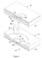
FIG. 1 , a shock suppressor in accordance with the present invention can be applied to a building, a bridge or an instrument and comprises a first base (10), a second base (20), a sliding holder assembly (40) and a connecting device (30). - The second base (20) is parallel to the first base (10). The connecting device (30) is slidably mounted between the first base (10) and second base (20) to connect the first and second bases (10,20). The first base (10) is connected with the connecting device (30) in curved contact surfaces to provide a first sliding mechanism in multiple directions. The second base (20) is connected with the connecting device (30) to provide a second sliding mechanism in a unidirection. The sliding holder assembly (40) is mounted between the connecting device (30) and at least one of the bases (10,20) in a universal contacting manner.
- A damping device (50) is mounted on at least one of the first base (10) and the second base (20). The damping device (50) can be made of resilient rubber material, viscoelastic material, frictional material or material with an excellent damping coefficient.
- In practice, the locations of the first and second bases (10,20) can be exchanged based on different needs. The first base (10) can be mounted on the ground, the floor or a building and is located below the second base (20). In an alternative embodiment, the second base (20) can be mounted on the ground, the floor or a building and is located below the first base (10).
- With reference to
FIG. 1 , in a first embodiment of a shock suppressor in accordance with the present invention, the first base (10) has a concave surface (11) defined in a side facing the second base (20). The second base (20) has an elongated sliding channel (21) defined in a side facing the first base (10), and the sliding channel (21) has a concave surface (22) facing the first base (10). The damping device (50) comprises two damping pads attached respectively to the first and second bases (10,20). - The sliding holder assembly (40) comprises a first holder (401) and a second holder (402). The first holder (401) is slidably in the concave surface (11) in the first base (10) has a convex bottom (41) abutting and matching with the concave surface (11) in the first base (10). A recess (42) with a concave bottom is defined in the first holder (401) at a side facing the second base (20) and the second holder (402) to form an annular wall (43) around the first holder (401). The recess (42) in the first holder (401) has a diameter larger than that of the connecting device (30).
- The second holder (402) is held slidably in sliding channel (21) in the second base (20) and has a convex bottom (44) abutting and matching with the concave surface (22) in the sliding channel (21). A recess (45) with a concave bottom is defined in the second holder (402) at a side facing the first holder (401) to form two limiting flanges (46) respectively at two ends of the second holder (402).
- The connecting device (30) may be cylindrical rod having two convex ends (301,302) abutting and matching respectively with the concave bottoms of the recesses (42,45) in the holders (401,402). The connecting device (30) further has two guiding sides respectively abutting against the inner sides of the sliding channel (21).
- With the concave surface (11) in the first base (10), the convex bottom (41) of the first holder (401), the concave bottom of the recess (42) and the convex end (301) on the connecting device (30), the first sliding mechanism between the first base (10) and the connecting device (30) in a curved contact surface is achieved.
- With the concave surface (22) of the sliding channel (21), the convex bottom (44) of the second holder (402), the concave bottom of the recess (45) and the convex end (302) on the connecting device (30), the second sliding mechanism between the second base (20) and the connecting device (30) in a unidirectional sliding direction is achieved.
- In such an arrangement, the connecting device (30) can provide an excellent supporting effect to the supported structures including buildings, bridges, etc. before a shock occurring. When a shock occurs, the first base (10) will move relative to the second base (20). With the arrangements of the sliding mechanisms between the bases (10,12), the sliding holder assembly (40) and the connecting device (30) and the damping device (50), the shock energy can be efficiently dissipated, eliminated, suppressed or absorbed in both horizontal and vertical directions.
- When the shock has stopped, the first and second bases (10,20) will automatically move to an original position with the concave and convex surfaces in the bases (10,12), the holders (401,402) and the connecting device (30), such that the shock suppressor has an automatic positioning effect to an original status. In additional, with the arrangement of the holders (401,402) of the sliding holder assembly (40), the movement of the bases (10,20) to the original position is quick and stable.
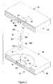
- With reference to
FIG. 2 , in a second embodiment of the shock suppressor, the connecting device (30A) comprises a first slider (31), a second slider (32) and a universal connector. The first slider (31) has a facing end facing to the second slider (32) and a convex end (311) formed on the first slider (31) at an end opposite to the facing end and abutting and matching with the concave bottom of the recess (42) in the first holder (401). - The second slider (32) has a facing end facing to the first slider (31) and a convex end (322) formed on the second slider (32) at an end opposite to the facing end and abutting and matching with the concave bottom of the recess (45) in the second holder (402). In addition, the second slider (32) further has two guiding sides (321) respectively abutting against the inner sides of the sliding channel (21).
- The universal connector is mounted between the first slider (31) and the second slider (32) and comprises two recesses (312,323) and a supporting member (33). The recesses (312,323) are defined respectively in the facing ends of the first slider (31) and the second slider (32). The supporting member (33) is rotatably mounted in the recesses (312,323) in the first and second sliders (31,32). In the second embodiment, the recesses (312,323) in the first and second sliders (31,32) are hemispherical, and the supporting member (33) is spherical.
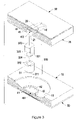
- With reference to
FIG. 3 , the third embodiment of the shock suppressor has a structure substantially same as that in the second embodiment except that the universal connector of the connecting device (30B) comprises a recess (312) defined in the facing end of the first slider (31) and a convex protrusion (324) formed on the facing end of the second slider (32B) and rotatably held in the recess (312) in the first slider (31). The recess (312) in the first slider (31) and the convex protrusion (324) on the second slider (32B) are hemispherical. - With reference to
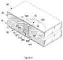
FIG. 4 , the fourth embodiment of the shock suppressor has a structure substantially same as that in the second embodiment except that the universal connector of the connecting device (30C) comprises a recess (323) defined in the facing end of the second slider (32C) and a convex surface (313) formed on the facing end of the first slider (31C) and rotatably held in the recess (323) in the second slider (32C). The recess (323) in the second slider (32C) is hemispherical, and the first slider (31C) is a hemispherical block with a hemispherical convex surface (313) rotatably held in the recess (323) in the second slider (32C). - With reference to
FIG. 5 , in a fifth embodiment of the shock suppressor, the first slider (31D) of the connecting device (30D) is a flat round block, the recess (323D) in the second slider (32D) is a flat concave recess, and the convex surface (313D) on the first slider (31D) is a flat convex surface. - With reference to
FIG. 6 , in a sixth embodiment of the shock suppressor, the second base (20A) has two parallel side plates (23) formed on and extending from the side facing the first base (10) and a guiding block (24) mounted between the side plates (23) to define the sliding channel (21A) between the side plates (23) and the guiding block (24). The guiding block (24) has a concave surface (22A) facing the first base (10) and corresponding to and matching with the convex bottom (44) on the second holder (402). - With reference to
FIG. 7 , in a seventh embodiment of the shock suppressor, the connecting device (30A) has a first slider (31A), a second slider (32A) and a universal connector with same structures as that in the second embodiment. - With reference to
FIG. 8 , in an eighth embodiment of the shock suppressor, the universal connector of the connecting device (30B) comprises a hemispherical recess (312) defined in the facing end of the first slider (31) and a hemispherical convex protrusion (324) formed on the facing end of the second slider (32B) and rotatably held in the recess (312) in the first slider (31). - With reference to
FIG. 9 , in a ninth embodiment of the shock suppressor, the second base (20B) has a rail (25) attached to the side facing the first base (10). The rail (25) has a curved rib (251) with a concave surface facing the first base (10). The connecting device (30E) has an engaging channel (303) corresponding to and matching with the curved rib (251) on the rail (25). The curved rib (251) of the rail (25) on the second base (20B) and the engaging channel (303) in the connecting device (30E) may have a V-shaped cross section, a semispherical cross section or an inverse T-shaped cross section as shown inFIG. 12 . Accordingly, the second sliding mechanism in a unidirectional sliding direction is constructed of the rib (251) and the engaging channel (303) and the sliding holder assembly (40A) is without the second holder. - With reference to
FIG. 10 , in a tenth embodiment of the shock suppressor, the second slider (32F) of the connecting device (30F) has an engaging channel (325F) corresponding to and matching with the curved rib (251) on the rail (25). - With reference to
FIG. 11 , the eleventh embodiment of the shock suppressor has a structure substantially same as that in the tenth embodiment except that the universal connector of the connecting device (30G) comprises a hemispherical recess (312) defined in the facing end of the first slider (31) and a hemispherical convex protrusion (324) formed on the facing end of the second slider (32G) and rotatably held in the recess (312) in the first slider (31). - With reference to
FIG. 12 , in a twelfth embodiment of the shock suppressor, the rib (261) of the rail (26) on the second base (20C) and the engaging channel (325) in the connecting device (30H) have an inverse T-shaped cross section. - With reference to
FIG. 13 , in the thirteenth embodiment of the shock suppressor, the rib (261) of the rail (26) on the second base (20C) and the engaging channel (326) in the second slider (321) of the connecting device (30I) have an inverse T-shaped cross section. - With reference to
FIG. 14 , the fourteenth embodiment of the shock suppressor has a structure substantially same as that in the thirteenth embodiment except that the universal connector of the connecting device (30J) comprises a hemispherical recess (312) defined in the facing end of the first slider (31) and a hemispherical convex protrusion (324) formed on the facing end of the second slider (323) and rotatably held in the recess (312) in the first slider (31). - With reference to
FIG. 15 , in the fifteenth embodiment of the shock suppressor, the rail (27) on the second base (20D) further has a flat and unidirectional rib (271) matching and engaging with an engaging channel (304) defined in the connecting device (30K), and the sliding holder assembly (40A) is without the second holder. The rail (27) further has a bar extending through the connecting device (30K) and two resilient members (272) mounted around the bar and abutting against the connecting device (30K). The resilient members (272) may be springs, plastic sleeves or cylinders. With the arrangement of the resilient members (272), the resilient members (272) can provide a recoil force to the connecting device (30K) to make the connecting device (30K) to move automatically to the original status. - With reference to
FIG. 16 , in the sixteenth embodiment of the shock suppressor, the second holder (32L) of the connecting device (30L) has an engaging channel (304) engaging with the flat and unidirectional rib (271) of the rail (27) on the second base (20D). The bar of the rail (27) extends through the second slider (32L), and the resilient members (272) abuts against the second slider (32L). - With reference to
FIG. 17 , the seventeenth embodiment of the shock suppressor has a structure substantially same as that in the sixteenth embodiment except that the universal connector of the connecting device (30M) comprises a hemispherical recess (312) defined in the facing end of the first slider (31) and a hemispherical convex protrusion (324) formed on the facing end of the second slider (32M) and rotatably held in the recess (312) in the first slider (31). - With such an arrangement, shock energy in multiple directions can be efficiently dissipated by the shock suppressor in accordance with the present invention. Additionally, with the first sliding mechanism in a universal direction and the second sliding mechanism in a unidirectional sliding direction, the displacement capacities and shock-dissipating frequencies in different direction are different. Therefore, the shock suppressor can be applied to bridges or elongated building and is versatile in use.
- Furthermore, the shock suppressor has a simplified structure, such that to manufacture and assemble the shock suppressor is easy and convenient and the cost for manufacturing the shock suppressor can be reduced.
- Even though numerous characteristics and advantages of the present invention have been set forth in the foregoing description, together with details of the structure and function of the invention, the disclosure is illustrative only, and changes may be made in detail, especially in matters of shape, size, and arrangement of parts within the principles of the invention to the full extent indicated by the broad general meaning of the terms in which the appended claims are expressed.
Claims (25)
1. A shock suppressor comprising:
a first base;
a second base being parallel to the first base;
a connecting device slidably mounted between the first base and second base to connect the first and second bases; and
a sliding holder assembly mounted between the connecting device and at least one of the bases in a universal contacting manner,
wherein, the first base is connected with the connecting device in a curved contact surface to provide a first sliding mechanism in multiple directions; and
the second base is connected with the connecting device to provide a second sliding mechanism in a unidirection.
2. The shock suppressor as claimed in claim 1 , wherein the first base has a concave surface defined in a side facing the second base;
the sliding holder assembly comprises a first holder slidably mounted in the concave surface in the first base and having
a convex bottom abutting and matching with the concave surface in the first base; and
a recess with a concave bottom being defined in the first holder at a side facing the second base to form an annular wall around the first holder; and
the connecting device has a convex end formed on one end of the connecting device and corresponding to and matching with the concave bottom of the recess in the first holder.
3. The shock suppressor as claimed in claim 2 , wherein
the second base has an elongated sliding channel defined in a side facing the first base, and the sliding channel has a concave surface facing the first base;
the sliding holder assembly comprises a second holder held slidably in sliding channel in the second base and having
a convex bottom abutting and matching with the concave surface in the sliding channel; and
a recess with a concave bottom being defined in the second holder at a side facing the first holder to form two limiting flanges respectively at two ends of the second holder; and
the connecting device has a convex end formed on one end of the connecting device and corresponding to and matching with the concave bottom of the recess in the second holder.
4. The shock suppressor as claimed in claim 3 , wherein
the connecting device comprises
a first slider abutting the concave bottom in the first holder and having a facing end facing to the second slider;
a second slider abutting the concave bottom in the second holder and having a facing end facing to the first slider; and
a universal connector is formed between the first slider and the second slider.
5. The shock suppressor as claimed in claim 4 further comprising a damping device mounted on at least one of the first base and the second base.
6. The shock suppressor as claimed in claim 4 , wherein the universal connector comprises
two recesses defined respectively in the facing ends of the first slider and the second slider; and
a supporting member rotatably mounted in the recesses in the first and second sliders.
7. The shock suppressor as claimed in claim 6 , wherein the recesses in the first and second sliders are hemispherical; and
the supporting member is spherical.
8. The shock suppressor as claimed in claim 4 , wherein the universal connector comprises
a recess defined in the facing end of the first slider; and
a convex protrusion formed on the facing end of the second slider and rotatably held in the recess in the first slider.
9. The shock suppressor as claimed in claim 8 , wherein the recess in the first slider and the convex protrusion on the second slider are hemispherical.
10. The shock suppressor as claimed in claim 4 , wherein the universal connector comprises
a recess defined in the facing end of the second slider; and
a convex surface formed on the facing end of the first slider and rotatably held in the recess in the second slider.
11. The shock suppressor as claimed in claim 10 , wherein the first slider is a hemispherical block;
the recess in the second slider is a hemispherical recess; and
the convex surface on the first slider is a hemispherical surface.
12. The shock suppressor as claimed in claim 10 , wherein the first slider is a flat round block;
the recess in the second slider is a flat concave recess; and
the convex surface on the first slider is a flat convex surface.
13. The shock suppressor as claimed in claim 3 , wherein
the second base has a side facing the first base, two parallel side plates parallelly mounted on the side of the second base and a guiding block attached between the side plates to form the sliding channel between the side plates and the guiding block;
the guiding block has a concave surface facing the first base; and
one of the convex end of the connecting device corresponding to and matching with the concave surface on the guiding block.
14. The shock suppressor as claimed in claim 13 , wherein the sliding channel has two sides; and
the connecting device has two guiding sides slidably and respectively abutting against the sides of the sliding channel.
15. The shock suppressor as claimed in claim 3 , wherein the sliding channel has two sides; and
the connecting device has two guiding sides slidably and respectively abutting against the sides of the sliding channel.
16. The shock suppressor as claimed in claim 15 further comprising a damping device mounted on at least one of the first base and the second base.
17. The shock suppressor as claimed in claim 1 , wherein
the second base has a side facing the first base and a rail attached to the side facing the first base, and the rail has a curved rib with a concave surface facing the first base; and
the connecting device has an engaging channel corresponding to and matching with the curved rib on the rail.
18. The shock suppressor as claimed in claim 17 , wherein the sliding holder assembly comprises a first holder slidably mounted in the concave surface in the first base and having
a convex bottom abutting and matching with the concave surface in the first base; and
a recess with a concave bottom being defined in the first holder at a side facing the second base to form an annular wall around the first holder; and
the connecting device has a convex end formed on one end of the connecting device and corresponding to and matching with the concave bottom of the recess in the first holder.
19. The shock suppressor as claimed in claim 18 further comprising a damping device mounted on at least one of the first base and the second base.
20. The shock suppressor as claimed in claim 18 , wherein the curved rib on the rail and the engaging channel of the connecting device have a V-shaped cross section.
21. The shock suppressor as claimed in claim 18 , wherein the curved rib on the rail and the engaging channel of the connecting device have an inverse T-shaped cross section.
22. The shock suppressor as claimed in claim 1 , wherein the second base has a side facing the first base and a rail attached to the side facing the first base, and the rail comprises
a flat and unidirectional rib matching and engaging with the engaging channel defined in the connecting device;
a bar extending through the connecting device; and
two resilient members mounted around the bar and abutting against the connecting device.
23. The shock suppressor as claimed in claim 22 , wherein the sliding holder assembly comprises a first holder slidably mounted in the concave surface in the first base and having
a convex bottom abutting and matching with the concave surface in the first base; and
a recess with a concave bottom being defined in the first holder at a side facing the second base to form an annular wall around the first holder; and
the connecting device has a convex end formed on one end of the connecting device and corresponding to and matching with the concave bottom of the recess in the first holder.
24. The shock suppressor as claimed in claim 23 further comprising a damping device mounted on at least one of the first base and the second base.
25. The shock suppressor as claimed in claim 1 further comprising a damping device mounted on at least one of the first base and the second base.
Applications Claiming Priority (2)
| Application Number | Priority Date | Filing Date | Title |
|---|---|---|---|
| TW095140216 | 2006-10-31 | ||
| TW095140216A TW200819596A (en) | 2006-10-31 | 2006-10-31 | Shock suppressor capable of dissipating seismic shock energy of different frequencies |
Publications (1)
| Publication Number | Publication Date |
|---|---|
| US20080098671A1 true US20080098671A1 (en) | 2008-05-01 |
Family
ID=39328471
Family Applications (1)
| Application Number | Title | Priority Date | Filing Date |
|---|---|---|---|
| US11/925,205 Abandoned US20080098671A1 (en) | 2006-10-31 | 2007-10-26 | Shock suppressor |
Country Status (2)
| Country | Link |
|---|---|
| US (1) | US20080098671A1 (en) |
| TW (1) | TW200819596A (en) |
Cited By (18)
| Publication number | Priority date | Publication date | Assignee | Title |
|---|---|---|---|---|
| US20060272225A1 (en) * | 2005-05-18 | 2006-12-07 | Chong-Shien Tsai | Shock suppressor |
| US20080120927A1 (en) * | 2006-11-28 | 2008-05-29 | Chong-Shien Tsai | Shock suppressor |
| US20090013619A1 (en) * | 2007-07-13 | 2009-01-15 | Carlos Marroquin | Earthquake resistant house |
| US20100095608A1 (en) * | 2007-02-06 | 2010-04-22 | Alga S.P.A. | Sliding pendulum seismic isolator |
| US20120174500A1 (en) * | 2009-07-15 | 2012-07-12 | Haisam Yakoub | Frictional Non Rocking Damped Base Isolation System To Mitigate Earthquake Effects On Structures |
| US20120260586A1 (en) * | 2009-10-21 | 2012-10-18 | Kunihiro Thubota | Seismic isolation system having damper type damping mechanism |
| US8789320B1 (en) | 2013-07-18 | 2014-07-29 | R. J. Watson, Inc. | Large displacement isolation bearing |
| US8926180B2 (en) | 2013-03-18 | 2015-01-06 | R. J. Watson, Inc. | Disc and spring isolation bearing |
| US9175468B1 (en) * | 2014-07-09 | 2015-11-03 | Chong-Shien Tsai | Shock suppressor |
| US20150361657A1 (en) * | 2014-06-16 | 2015-12-17 | Universiti Putra Malaysia | Variable stiffness bracing device |
| US9644384B2 (en) * | 2015-02-12 | 2017-05-09 | Star Seismic, Llc | Buckling restrained brace and related methods |
| US10208437B1 (en) * | 2017-08-15 | 2019-02-19 | Sichuan University | Damping bearing in convertible antiseismic mode and damping bridge apparatus |
| US20200141148A1 (en) * | 2017-05-10 | 2020-05-07 | Nippon Steel & Sumikin Engineering Co., Ltd. | Sliding seismic isolation device |
| US11136779B2 (en) * | 2017-01-10 | 2021-10-05 | Heung Yeol KIM | Seismic isolation device |
| US20220251863A1 (en) * | 2021-02-09 | 2022-08-11 | National Taiwan University Of Science And Technology | Seismic isolation device |
| US11421435B2 (en) * | 2018-12-12 | 2022-08-23 | Universidad Catolica De La Santisima Concepcion | Kinematic seismic isolation device |
| US20240084954A1 (en) * | 2022-02-23 | 2024-03-14 | Taiwan Semiconductor Manufacturing Company, Ltd. | Displacement control device for seismic events |
| US12091849B2 (en) * | 2020-12-10 | 2024-09-17 | Tsinghua University | Double-friction pendulum three-dimensional vibration isolation bearing |
Citations (16)
| Publication number | Priority date | Publication date | Assignee | Title |
|---|---|---|---|---|
| US2014643A (en) * | 1933-08-31 | 1935-09-17 | Jacob F J Bakker | Balance block for buildings |
| US4644714A (en) * | 1985-12-02 | 1987-02-24 | Earthquake Protection Systems, Inc. | Earthquake protective column support |
| US4883250A (en) * | 1987-03-12 | 1989-11-28 | Kajima Corporation | Vibration-proof and earthquake-immue mount system |
| US5599106A (en) * | 1994-02-09 | 1997-02-04 | Tekton | Ball-in-cone seismic isolation bearing |
| US5934029A (en) * | 1997-05-16 | 1999-08-10 | Okumura Corporation | Base isolator having mutually eccentric rotators |
| US6123313A (en) * | 1997-06-25 | 2000-09-26 | Okumura Corporation | Seismic isolation apparatus |
| US6164022A (en) * | 1997-09-04 | 2000-12-26 | Thk Co., Ltd. | Three dimensional guide |
| US6321492B1 (en) * | 1997-08-08 | 2001-11-27 | Robinson Seismic Limited | Energy absorber |
| US6364274B1 (en) * | 1999-11-18 | 2002-04-02 | Mitsubishi Steel Mfg. Co., Ltd. | Seismic isolator for exhibits |
| US20030094560A1 (en) * | 2001-11-16 | 2003-05-22 | Chung-Shien Tsai | Shock eliminator |
| US6631593B2 (en) * | 2000-07-03 | 2003-10-14 | Jae Kwan Kim | Directional sliding pendulum seismic isolation systems and articulated sliding assemblies therefor |
| US20040074163A1 (en) * | 2002-03-07 | 2004-04-22 | Chong-Shien Tsai | Structure of an anti-shock device |
| US6725612B2 (en) * | 2001-05-04 | 2004-04-27 | Jae Kwan Kim | Directional rolling pendulum seismic isolation systems and roller assembly therefor |
| US20060174555A1 (en) * | 2006-05-12 | 2006-08-10 | Earthquake Protection Systems, Inc. | Sliding Pendulum Seismic Isolation System |
| US20070044395A1 (en) * | 2005-08-24 | 2007-03-01 | Lyan-Ywan Lu | Seismic isolator with variable curvature |
| US20080078633A1 (en) * | 2006-08-08 | 2008-04-03 | Chong-Shien Tsai | Shock suppressor |
-
2006
- 2006-10-31 TW TW095140216A patent/TW200819596A/en not_active IP Right Cessation
-
2007
- 2007-10-26 US US11/925,205 patent/US20080098671A1/en not_active Abandoned
Patent Citations (17)
| Publication number | Priority date | Publication date | Assignee | Title |
|---|---|---|---|---|
| US2014643A (en) * | 1933-08-31 | 1935-09-17 | Jacob F J Bakker | Balance block for buildings |
| US4644714A (en) * | 1985-12-02 | 1987-02-24 | Earthquake Protection Systems, Inc. | Earthquake protective column support |
| US4883250A (en) * | 1987-03-12 | 1989-11-28 | Kajima Corporation | Vibration-proof and earthquake-immue mount system |
| US5599106A (en) * | 1994-02-09 | 1997-02-04 | Tekton | Ball-in-cone seismic isolation bearing |
| US5934029A (en) * | 1997-05-16 | 1999-08-10 | Okumura Corporation | Base isolator having mutually eccentric rotators |
| US6123313A (en) * | 1997-06-25 | 2000-09-26 | Okumura Corporation | Seismic isolation apparatus |
| US6321492B1 (en) * | 1997-08-08 | 2001-11-27 | Robinson Seismic Limited | Energy absorber |
| US6164022A (en) * | 1997-09-04 | 2000-12-26 | Thk Co., Ltd. | Three dimensional guide |
| US6364274B1 (en) * | 1999-11-18 | 2002-04-02 | Mitsubishi Steel Mfg. Co., Ltd. | Seismic isolator for exhibits |
| US6631593B2 (en) * | 2000-07-03 | 2003-10-14 | Jae Kwan Kim | Directional sliding pendulum seismic isolation systems and articulated sliding assemblies therefor |
| US6725612B2 (en) * | 2001-05-04 | 2004-04-27 | Jae Kwan Kim | Directional rolling pendulum seismic isolation systems and roller assembly therefor |
| US20030094560A1 (en) * | 2001-11-16 | 2003-05-22 | Chung-Shien Tsai | Shock eliminator |
| US20040074163A1 (en) * | 2002-03-07 | 2004-04-22 | Chong-Shien Tsai | Structure of an anti-shock device |
| US6820380B2 (en) * | 2002-03-07 | 2004-11-23 | Chong-Shien Tsai | Structure of an anti-shock device |
| US20070044395A1 (en) * | 2005-08-24 | 2007-03-01 | Lyan-Ywan Lu | Seismic isolator with variable curvature |
| US20060174555A1 (en) * | 2006-05-12 | 2006-08-10 | Earthquake Protection Systems, Inc. | Sliding Pendulum Seismic Isolation System |
| US20080078633A1 (en) * | 2006-08-08 | 2008-04-03 | Chong-Shien Tsai | Shock suppressor |
Cited By (28)
| Publication number | Priority date | Publication date | Assignee | Title |
|---|---|---|---|---|
| US7716881B2 (en) * | 2005-05-18 | 2010-05-18 | Chong-Shien Tsai | Shock suppressor |
| US20060272225A1 (en) * | 2005-05-18 | 2006-12-07 | Chong-Shien Tsai | Shock suppressor |
| US20080120927A1 (en) * | 2006-11-28 | 2008-05-29 | Chong-Shien Tsai | Shock suppressor |
| US7814712B2 (en) * | 2006-11-28 | 2010-10-19 | Chong-Shien Tsai | Shock suppressor |
| US8011142B2 (en) * | 2007-02-06 | 2011-09-06 | Alga S.P.A. | Sliding pendulum seismic isolator |
| US20100095608A1 (en) * | 2007-02-06 | 2010-04-22 | Alga S.P.A. | Sliding pendulum seismic isolator |
| US20090013619A1 (en) * | 2007-07-13 | 2009-01-15 | Carlos Marroquin | Earthquake resistant house |
| US20120174500A1 (en) * | 2009-07-15 | 2012-07-12 | Haisam Yakoub | Frictional Non Rocking Damped Base Isolation System To Mitigate Earthquake Effects On Structures |
| US20140338271A1 (en) * | 2009-07-15 | 2014-11-20 | Haisam Yakoub | Frictional non rocking seismic base isolator for structure seismic protection (fnsi) |
| US9021751B2 (en) * | 2009-07-15 | 2015-05-05 | Haisam Yakoub | Frictional non rocking damped base isolation system to mitigate earthquake effects on structures |
| US20120260586A1 (en) * | 2009-10-21 | 2012-10-18 | Kunihiro Thubota | Seismic isolation system having damper type damping mechanism |
| US8926180B2 (en) | 2013-03-18 | 2015-01-06 | R. J. Watson, Inc. | Disc and spring isolation bearing |
| US8789320B1 (en) | 2013-07-18 | 2014-07-29 | R. J. Watson, Inc. | Large displacement isolation bearing |
| US20150361657A1 (en) * | 2014-06-16 | 2015-12-17 | Universiti Putra Malaysia | Variable stiffness bracing device |
| US9447597B2 (en) * | 2014-06-16 | 2016-09-20 | Universiti Putra Malaysia | Variable stiffness bracing device |
| US9175468B1 (en) * | 2014-07-09 | 2015-11-03 | Chong-Shien Tsai | Shock suppressor |
| US9644384B2 (en) * | 2015-02-12 | 2017-05-09 | Star Seismic, Llc | Buckling restrained brace and related methods |
| US9909335B2 (en) | 2015-02-12 | 2018-03-06 | Star Seismic, Llc | Buckling restrained braces and related methods |
| US11136779B2 (en) * | 2017-01-10 | 2021-10-05 | Heung Yeol KIM | Seismic isolation device |
| US10767384B2 (en) * | 2017-05-10 | 2020-09-08 | Nippon Steel & Sumikin Engineering Co., Ltd. | Sliding seismic isolation device |
| US20200141148A1 (en) * | 2017-05-10 | 2020-05-07 | Nippon Steel & Sumikin Engineering Co., Ltd. | Sliding seismic isolation device |
| US10208437B1 (en) * | 2017-08-15 | 2019-02-19 | Sichuan University | Damping bearing in convertible antiseismic mode and damping bridge apparatus |
| US11421435B2 (en) * | 2018-12-12 | 2022-08-23 | Universidad Catolica De La Santisima Concepcion | Kinematic seismic isolation device |
| US12091849B2 (en) * | 2020-12-10 | 2024-09-17 | Tsinghua University | Double-friction pendulum three-dimensional vibration isolation bearing |
| US20220251863A1 (en) * | 2021-02-09 | 2022-08-11 | National Taiwan University Of Science And Technology | Seismic isolation device |
| US11821234B2 (en) * | 2021-02-09 | 2023-11-21 | National Taiwan University Of Science And Technology | Seismic isolation device |
| US20240084954A1 (en) * | 2022-02-23 | 2024-03-14 | Taiwan Semiconductor Manufacturing Company, Ltd. | Displacement control device for seismic events |
| US12467578B2 (en) * | 2022-02-23 | 2025-11-11 | Taiwan Semiconductor Manufacturing Company, Ltd. | Displacement control device for seismic events |
Also Published As
| Publication number | Publication date |
|---|---|
| TWI320444B (en) | 2010-02-11 |
| TW200819596A (en) | 2008-05-01 |
Similar Documents
| Publication | Publication Date | Title |
|---|---|---|
| US20080098671A1 (en) | Shock suppressor | |
| US8161695B2 (en) | Shock supressor | |
| US7814712B2 (en) | Shock suppressor | |
| US9175468B1 (en) | Shock suppressor | |
| JP5774266B2 (en) | Sliding alignment support and its usage | |
| EP2821668B1 (en) | Vibration-insulating device and system | |
| ES2404879T3 (en) | Device to isolate an object from external movements | |
| CN101701477B (en) | Arc-shaped steel spring plate vibration isolation support of friction pendulum | |
| US7716881B2 (en) | Shock suppressor | |
| CN101725109A (en) | Dilatation joint of bridge | |
| JP4410725B2 (en) | Vertical seismic isolation unit and seismic isolation device using the same | |
| US11058019B1 (en) | Electronic device | |
| CN215215064U (en) | Pipeline antidetonation support in building | |
| JP4822162B2 (en) | Vibration control device | |
| CN101153504A (en) | Vibration isolator with multi-direction and different frequency | |
| JP2011021739A (en) | Base isolation unit | |
| TWI558931B (en) | Isolator | |
| CN100516395C (en) | Double-curved shock insulation and energy dissipation device | |
| KR20200076058A (en) | Seismic construction structure | |
| CN211040213U (en) | Damping device and monitoring system and robot having the same | |
| JP7558836B2 (en) | Slip-absorbing device | |
| TWI506210B (en) | The sliding joint seismic isolation bearing, the vibration isolation method of its application, the vibration isolation structure of its application, the mass dampers of its application | |
| CN112502036A (en) | Resettable multidirectional movable support with shock absorption and isolation effects | |
| CN223563352U (en) | Vibration isolation device | |
| CN116819628B (en) | Submarine seismic acquisition system |
Legal Events
| Date | Code | Title | Description |
|---|---|---|---|
| STCB | Information on status: application discontinuation |
Free format text: ABANDONED -- FAILURE TO RESPOND TO AN OFFICE ACTION |