US20080098609A1 - Dip stick - Google Patents
Dip stick Download PDFInfo
- Publication number
- US20080098609A1 US20080098609A1 US11/553,644 US55364406A US2008098609A1 US 20080098609 A1 US20080098609 A1 US 20080098609A1 US 55364406 A US55364406 A US 55364406A US 2008098609 A1 US2008098609 A1 US 2008098609A1
- Authority
- US
- United States
- Prior art keywords
- dip stick
- wiper
- block
- assembly
- dip
- Prior art date
- Legal status (The legal status is an assumption and is not a legal conclusion. Google has not performed a legal analysis and makes no representation as to the accuracy of the status listed.)
- Granted
Links
- 230000000903 blocking effect Effects 0.000 claims abstract description 18
- 238000000034 method Methods 0.000 claims description 9
- 239000012530 fluid Substances 0.000 claims description 8
- 238000004891 communication Methods 0.000 claims description 3
- 230000008878 coupling Effects 0.000 claims 2
- 238000010168 coupling process Methods 0.000 claims 2
- 238000005859 coupling reaction Methods 0.000 claims 2
- 238000004140 cleaning Methods 0.000 description 5
- 239000004744 fabric Substances 0.000 description 5
- 230000013011 mating Effects 0.000 description 3
- 230000009471 action Effects 0.000 description 2
- 230000000712 assembly Effects 0.000 description 2
- 238000000429 assembly Methods 0.000 description 2
- 238000005259 measurement Methods 0.000 description 2
- 238000012986 modification Methods 0.000 description 2
- 230000004048 modification Effects 0.000 description 2
- 230000008569 process Effects 0.000 description 2
- 230000000881 depressing effect Effects 0.000 description 1
- 238000007373 indentation Methods 0.000 description 1
- 238000003780 insertion Methods 0.000 description 1
- 230000037431 insertion Effects 0.000 description 1
- 230000007246 mechanism Effects 0.000 description 1
- 239000012858 resilient material Substances 0.000 description 1
- 230000000284 resting effect Effects 0.000 description 1
Images


Classifications
-
- G—PHYSICS
- G01—MEASURING; TESTING
- G01F—MEASURING VOLUME, VOLUME FLOW, MASS FLOW OR LIQUID LEVEL; METERING BY VOLUME
- G01F23/00—Indicating or measuring liquid level or level of fluent solid material, e.g. indicating in terms of volume or indicating by means of an alarm
- G01F23/04—Indicating or measuring liquid level or level of fluent solid material, e.g. indicating in terms of volume or indicating by means of an alarm by dip members, e.g. dip-sticks
- G01F23/045—Indicating or measuring liquid level or level of fluent solid material, e.g. indicating in terms of volume or indicating by means of an alarm by dip members, e.g. dip-sticks cleaning means therefor (e.g. dip-stick wipers)
Definitions
- This invention relates to a dip stick assembly for a vehicle.
- a dip stick is used to measure oil in an oil pan or, more broadly, an oil reservoir of a vehicle.
- the dip stick remains inserted in a housing that is connected to the oil reservoir.
- the dip stick will typically have some markings, which serve to reflect the level of oil in the reservoir.
- oil will splash onto the dip stick at points that do not accurately reflect the oil level.
- the dip stick is removed from the housing and is typically wiped clean with a cloth. The dip stick is then reinserted into the housing and then removed again to read the oil level, which then provides an accurate reflection of the oil level in the reservoir.
- This technique for checking the oil level in a vehicle has its drawbacks. Specifically, the technique is messy. One must have ready some way to wipe the dip stick clean, which is typically a cloth, paper towel or rag. Also, the cloth or such used to wipe the dip stick must be thrown away because it is difficult or impractical to clean, both wasting the cloth and causing the inconvenience of its disposal. Oil is also wasted because oil on the dip stick is left on the cloth rather than returned to the oil reservoir.
- the invention comprises a dip stick assembly and related technique.
- the dip stick has a measure for reading the oil level of an oil reservoir of a vehicle.
- the dip stick is received in a housing, which allows the dip stick to be inserted into the oil reservoir.
- the dip stick has wipers attached to the housing.
- the wipers have an engaged position and a disengaged position. In the engaged position, the wiper is in contact with the dip stick. In the disengaged position, the wiper is out of contact with the dip stick.
- the wipers may be resiliently biased into the engaged position so that the dip stick is automatically wiped when removed from the housing.
- a block is provided to prevent the wiper from moving into the engaged position. The block is moveable between a blocking position and an unblocking position. In the blocking position, the block maintains the wiper in the disengaged position, while, in the unblocking position, the block permits the wiper to move to the engaged position.
- the inventive dip stick assembly provides an automatic technique for cleaning the dip stick assembly.
- the dip stick is placed in communication with an oil reservoir.
- the wipers are biased into engagement with the dip stick.
- the wiper is prevented from engaging the dip stick by the block.
- the block is then removed to allow the wiper to contact the dip stick and wipe it.
- the dip stick is then reinserted.
- the block is returned to the blocking position and left there.
- the wipers remain in the disengaged position, thereby allowing the dip stick to be removed without wiping, thereby providing a simple and inexpensive assembly and technique for cleaning and reading the dip stick.
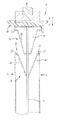
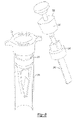
- FIG. 1 illustrates a version of the inventive dip stick assembly, including dip stick, housing, wipers and block.
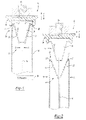
- FIG. 2 illustrates the dip stick assembly of FIG. 1 in which the wipers are in the engaged position to wipe the dip stick.
- FIG. 3 illustrates the block of FIGS. 1 and 2 in a blocking position to prevent the wipers from wiping the dip stick.
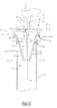
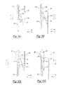
- FIG. 4 illustrates an alternative version of the inventive dip stick assembly.
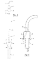
- FIG. 5 illustrates a block and release of the version of FIG. 4 .
- FIG. 6 illustrates another version of the inventive dip stick assembly with dip stick in unblocking position.
- FIG. 7 illustrates the version of the inventive dip stick assembly of FIG. 6 with dip stick in blocking position.
- FIG. 7A illustrates a plan view of the wiper support for the wipers of the dip stick assembly of FIGS. 5-7 .
- FIG. 8 illustrates the version of the inventive dip stick assembly of FIGS. 6 and 7 with dip stick removed from its housing.
- FIG. 9A illustrates another version of a dip stick assembly according to the invention with wipers disengaged.
- FIG. 9B illustrates the version of the dip stick assembly of FIG. 9A with the wipers engaged.
- FIG. 10A shows another version of the invention with wipers engaged.
- FIG. 10B shows the version of the invention of FIG. 10A with wipers disengaged.
- FIG. 1 illustrates inventive dip stick assembly 10 .
- Dip stick assembly 10 has dip stick 14 disposed in housing 18 as shown. Housing 18 is connected to oil reservoir 58 in a vehicle.
- Dip stick 14 has markings 15 that permit the fluid level of oil reservoir to be read by dip stick 14 as known.
- dip stick assembly 10 has wipers, such as wipers 22 and 24 , which pivot between engaged position 26 as shown in FIG. 2 and disengaged position 30 as shown in FIG. 1 .
- Wipers 22 , 24 are connected to housing 18 and are resiliently biased by springs 27 to engaged position 26 , which is in contact with dip stick 14 as shown in FIG. 2 .
- Wiper 22 is connected to housing 18 at pivot 23 while wiper 24 is connected to housing 18 at pivot 25 .
- Within pivot 23 and pivot 25 are springs 27 that urge wiper 22 in the direction of arrow A and urge wiper 24 in direction of arrow B when wiper 22 and 24 are in the disengaged position 30 as shown in FIG. 1 .
- Block 34 comprises a frustroconical hollow insert that is sized to be received within housing 18 .
- Block 34 has inclined surface 62 that engages wipers 22 and 24 and facilitates insertion of block 34 between wipers 22 , 24 .
- wipers 22 and 24 move in the direction of arrow A and the direction of arrow B, respectively, because of their spring bias toward engaged position 26 .
- engaged position 26 as shown in FIG. 2 , wiper 22 and 24 contact dip stick 18 so that when dip stick 14 is withdrawn, wipers 22 and 24 wipe excess oil off dip stick 14 .
- the blocking structure may comprise any form which prevents the engagement of the wipers with the dip stick, in which the block may also be, by way of example, a flat projection.
- the housing for the wiper and blocking structure need not be circular, as is normal for the pipe leading into the oil reservoir, but may also be rectangular or square.
- the wipers need not have the shape of standard wipers but may additionally be a resilient slot or an orifice which will retain or revert back to its original shape or position after a blocking structure is inserted in order to perform the repeated function of wiping the dip stick in a subsequent oil check.
- a wiper then is any structure which performs the function of wiping.
- wiper 22 and 24 are located within housing 18 . This permits oil wiped from dip stick 14 to be returned to oil reservoir 58 because wiped oil remains in housing 18 . After dip stick 14 is withdrawn in the direction of arrow E, it may then be reinserted into housing 18 by moving it in the direction of arrow F. Now, dip stick 14 is exposed to oil reservoir 58 after having been wiped by wiper 22 and 24 .
- Block 34 is releasably coupled to dip stick 14 by catches 84 , 86 , which are formed as part of cap 100 .
- Cap 100 is connected to dip stick 14 .
- Block 34 is shown in unreleased position 54 in FIGS. 1 and 2 .
- Cap 100 and catches 84 , 86 are made of a resilient material, such as plastic.
- Release 46 is slideably received in cap 100 and may move in the direction of arrow F to apply pressure to break 102 , which is a channel in the plastic to permit flexing of catches 84 , 86 in the direction of arrows C and D, respectively.
- release 46 is actuated by depressing it in the direction of arrow F.
- Dip stick 14 may then be withdrawn with oil unwiped from dip stick, thereby allowing dip stick 14 to be read for an accurate measurement of oil in oil reservoir 58 .
- block 34 has a hollow 64 that permits dip stick 14 to slide freely within block 34 when block 34 is released from cap 100 .
- FIG. 2 illustrates an alternative version of the inventive dip stick assembly.
- dip stick assembly 70 has block 60 .
- Block 60 has inclined surface 62 as well as curved portion 66 .
- block 60 is hollow and slideably receives dip stick 14 .
- Cap 96 is secured to dip stick 14 .
- assembly 70 has release 92 that when actuated, moves catch 94 by lever 97 in the direction of arrow D to release block 34 from engagement with cap 96 .
- Ball bearings are provided on cap 96 to permit block 60 to be slideably received within cap 96 .
- wipers 74 and 78 are attached externally to housing 18 , thereby permitting wipers 74 and 78 to be added to a vehicle in the aftermarket. They are mounted by fastener 100 , which has springs that are attached to housing 18 and arms 108 . As in the previous version, wiper 74 and 78 are resiliently biased to engage dip stick 14 when dip stick is inserted. Dip stick 14 is operated in the same way as dip stick assembly 10 .
- FIGS. 6 and 7 illustrate another version of the inventive dip stick assembly.
- Dip stick assembly 200 has dip stick 208 disposed in housing 220 , which is connected to an oil reservoir as known. Dip stick 208 is long enough to extend into the oil reservoir to accurately gauge the oil level. Disposed in housing 220 is wiper support 226 , which is locked in place to prevent movement in the direction of arrows I or J or rotation in the direction of arrows G or H. Wiper support 226 has wipers 204 . Like the other versions of the invention, dip stick assembly 200 has wipers 204 resiliently biased into engagement with dip stick.
- dip stick 208 is wiped by lifting dip stick 208 in the direction of arrow J.
- This action causes dip stick 208 to be wiped by wipers 204 , which are resiliently biased into engagement with face 212 and face 216 of dip stick 208 .
- Face 212 and face 216 has markings, such as a standard gauge for measuring oil level. Hence, faces 212 and 216 of dip stick 208 are cleaned before reinsertion into oil reservoir.
- Dip stick 208 is returned to a position where it is in contact with the oil level by lowering dip stick 208 in the direction of arrow I.
- Dip stick 208 is guided by guide 224 that has hole 228 shaped to receive mating component 232 so that when mating component 232 is returned to hole 228 , face 212 and face 216 are in contact with wipers 204 .
- This feature ensures the correct orientation of dip stick 208 and its faces 212 , 216 relative to wipers 204 so that wipers 204 may contact face 212 and face 216 to clean the surfaces of oil.
- dip stick 208 may be done without removal of dip stick 208 from housing 220 , thereby ensuring wiped oil remains within housing 220 .
- Dip stick 208 is provided with upper stop 236 and lower stop 240 .
- Upper stop 236 prevents dip stock 208 from traveling in the direction of arrow I beyond the point where dip stick 208 is calibrated with markings so that dip stick 208 will accurately measure the oil level.
- Guide 224 holds upper stop 236 at this point by preventing stop 236 from passing through hole 228 because of hole 228 's tapering shape.
- Lower stop 240 prevents dip stick 208 from being removed from housing 220 by its interference with wiper support 226 .
- FIG. 7A illustrates a plan view of housing 220 and wiper support 226 in the direction of arrow I, as shown in the position of FIG. 6 .
- wiper support 226 has a base 241 with hole 242 which is shaped and sized like wiper support 240 but, in this position, rotated about ninety degrees (90°) from the mating shape of wiper support 240 .
- wiper support 240 is blocked from moving past base 241 .
- upper stop 232 is prevented from traveling beyond guide 224 while lower stop 240 is prevented from traveling past base 241 of wiper support 240 .
- dip stick 208 can be pumped down in the direction of arrow I and pulled up in the direction of arrow J to clean dip stick 208 without removing it completely from its housing. It will be understood by one of ordinary skill in the art that wipers 204 must contact dip stick 208 at a point low enough so that when lower stop 240 is at the point of base 241 , wipers 204 will have wiped all of the level markings.
- Guide 224 is rotatably mounted to housing 220 to allow its movement in the direction of arrows G or H but to prevent its movement in the directions of arrows I or J.
- stops 300 and 302 are provided on wiper support 226 or, alternatively, on housing 220 , so that guide 224 may rotate 90 degrees between position X and position Y. Stops 300 and 302 may be detents.
- guide 224 is rotated from position shown in FIG. 6 in the direction of arrow G, say 90°. Rotation to position X causes dip stick 208 to block wipers 204 from engaging face 212 and face 216 of dip stick 208 . Also, as shown in FIG.
- lower support 240 will likewise be rotated to position X by rotation of guide 224 to this position so that lower stop 240 may now pass hole 242 .
- Lower stop 240 should be sized to pass freely through hole 228 too. Accordingly, as shown in FIG. 8 , when dip stick 208 is withdrawn with guide 224 in the direction of arrow D, dip stick 208 may then be read without having oil wiped off by wipers 204 .
- FIG. 9A illustrates another version of the invention.
- dip stick 300 is disposed in housing 304 , which is only partially shown.
- housing 304 may surround dip stick 300 as known.
- Housing 304 has block 308 , which is here a protrusion extending from its surface toward dip stick 300 .
- Wiper 312 is shown out of contact with dip stick 300 and resting on block 308 .
- Wiper 312 may be resiliently biased away from contact with dip stick 300 .
- wiper 312 is pivotally mounted on carrier 314 , which is slideably received on housing 304 and is configured to move up in the direction of arrow X or down in the direction of arrow Y.
- Wiper 312 may pivot in the direction of arrow T to move toward dip stick 300 or in the direction of arrow U away from dip stick 300 .
- carrier 314 slides down housing 304 in the direction of arrow Y, which causes wiper 312 to pivot in the direction of arrow T on block 308 .
- wiper 312 then cleans dip stick 300 of excess oil.
- Dip stick 300 is then returned to housing 304 in the direction of arrow Y.
- Carrier 314 is then moved in the direction of arrow X, causing wiper 312 to pivot away from dip stick 300 in the direction of arrow U so that dip stick 300 may then be withdrawn to take an accurate measurement of the oil level on dip stick 300 without being wiped by wiper 312 .
- Detents 318 and 322 may be provided to lock carrier 314 momentarily in position where wiper 312 is in contact with dip stick 300 and in position where wiper 312 is out of contact with dip stick 300 .
- FIG. 10A shows housing 326 having block 330 extending toward dip stick 300 .
- Wiper 334 is provided and pivotally mounted to carrier 338 , which is slideably mounted to housing 326 .
- Wiper 334 may be resiliently biased into contact with dip stick 300 as shown.
- Carrier 338 may be held momentarily in place by detent 318 here.
- Wiper 334 is also provided with catch 342 . With wiper 334 in contact with dip stick 300 , dip stick 300 may be withdrawn in the direction of arrow X to clean it of excess oil. Dip stick 300 may then be returned in the direction of arrow Y so that it may measure the oil level of the reservoir.
- carrier 338 is then moved in the direction of arrow Y along housing 326 , overcoming the resistance to movement provided by detent 318 to a position on housing 326 shown in FIG. 10B , wherein detent 322 is engaged to momentarily hold carrier 338 in place.
- catch 342 of wiper 334 moves into contact with block 330 , causing wiper 334 to swing away from dip stick 300 in the direction of arrow U.
- Wiper 334 may then be withdrawn from housing 326 again so that the fill level of oil may be correctly checked.
- carrier 338 may be moved back up in the direction of arrow X. Block 330 no longer holds wiper 334 out of contact with dip stick 330 . Due to its resilient bias, wiper 334 returns in the direction of arrow T to its position in contact with dip stick 300 as shown in FIG. 10A .
- dip sticks may be round with contoured wipers to engage the round cylindrical shape of the dip stick. In this way, dip stick need not be oriented relative to the wipers as the entire contoured surface of the dip stick would be wiped by the contour wipers.
Landscapes
- Physics & Mathematics (AREA)
- Fluid Mechanics (AREA)
- General Physics & Mathematics (AREA)
- General Details Of Gearings (AREA)
Abstract
Description
- This invention relates to a dip stick assembly for a vehicle.
- A dip stick is used to measure oil in an oil pan or, more broadly, an oil reservoir of a vehicle. Typically, the dip stick remains inserted in a housing that is connected to the oil reservoir. The dip stick will typically have some markings, which serve to reflect the level of oil in the reservoir. During normal operation of the vehicle, oil will splash onto the dip stick at points that do not accurately reflect the oil level. When the oil level is checked, the dip stick is removed from the housing and is typically wiped clean with a cloth. The dip stick is then reinserted into the housing and then removed again to read the oil level, which then provides an accurate reflection of the oil level in the reservoir.
- This technique for checking the oil level in a vehicle has its drawbacks. Specifically, the technique is messy. One must have ready some way to wipe the dip stick clean, which is typically a cloth, paper towel or rag. Also, the cloth or such used to wipe the dip stick must be thrown away because it is difficult or impractical to clean, both wasting the cloth and causing the inconvenience of its disposal. Oil is also wasted because oil on the dip stick is left on the cloth rather than returned to the oil reservoir.
- There have been efforts to simplify this process. Electronic systems exist that measure the level of oil in the vehicle. However, these systems are often unreliable or expensive. In addition, they normally only indicate if the level is low, not how low or how much oil is required to reach the proper level. Manual systems also exist that include wiping mechanisms on the housing. Although preferable to wiping the dip stick with a rag, these assemblies may be complicated, awkward to use or expensive.
- A need therefore exists for a dip stick assembly that simplifies the process for cleaning the dip stick without great expense or inconvenience.
- The invention comprises a dip stick assembly and related technique. The dip stick has a measure for reading the oil level of an oil reservoir of a vehicle. The dip stick is received in a housing, which allows the dip stick to be inserted into the oil reservoir. To facilitate cleaning, the dip stick has wipers attached to the housing. The wipers have an engaged position and a disengaged position. In the engaged position, the wiper is in contact with the dip stick. In the disengaged position, the wiper is out of contact with the dip stick.
- The wipers may be resiliently biased into the engaged position so that the dip stick is automatically wiped when removed from the housing. A block is provided to prevent the wiper from moving into the engaged position. The block is moveable between a blocking position and an unblocking position. In the blocking position, the block maintains the wiper in the disengaged position, while, in the unblocking position, the block permits the wiper to move to the engaged position.
- The inventive dip stick assembly provides an automatic technique for cleaning the dip stick assembly. The dip stick is placed in communication with an oil reservoir. The wipers are biased into engagement with the dip stick. The wiper, however, is prevented from engaging the dip stick by the block. The block is then removed to allow the wiper to contact the dip stick and wipe it. The dip stick is then reinserted. The block is returned to the blocking position and left there. When the dip stick is removed, the wipers remain in the disengaged position, thereby allowing the dip stick to be removed without wiping, thereby providing a simple and inexpensive assembly and technique for cleaning and reading the dip stick.
- The various features and advantages of this invention will become apparent to those skilled in the art from the following detailed description of the currently preferred embodiment. The drawings that accompany the detailed description can be briefly described as follows:
-
FIG. 1 illustrates a version of the inventive dip stick assembly, including dip stick, housing, wipers and block. -
FIG. 2 illustrates the dip stick assembly ofFIG. 1 in which the wipers are in the engaged position to wipe the dip stick. -
FIG. 3 illustrates the block ofFIGS. 1 and 2 in a blocking position to prevent the wipers from wiping the dip stick. -
FIG. 4 illustrates an alternative version of the inventive dip stick assembly. -
FIG. 5 illustrates a block and release of the version ofFIG. 4 . -
FIG. 6 illustrates another version of the inventive dip stick assembly with dip stick in unblocking position. -
FIG. 7 illustrates the version of the inventive dip stick assembly ofFIG. 6 with dip stick in blocking position. -
FIG. 7A illustrates a plan view of the wiper support for the wipers of the dip stick assembly ofFIGS. 5-7 . -
FIG. 8 illustrates the version of the inventive dip stick assembly ofFIGS. 6 and 7 with dip stick removed from its housing. -
FIG. 9A illustrates another version of a dip stick assembly according to the invention with wipers disengaged. -
FIG. 9B illustrates the version of the dip stick assembly ofFIG. 9A with the wipers engaged. -
FIG. 10A shows another version of the invention with wipers engaged. -
FIG. 10B shows the version of the invention ofFIG. 10A with wipers disengaged. -
FIG. 1 illustrates inventivedip stick assembly 10.Dip stick assembly 10 hasdip stick 14 disposed inhousing 18 as shown.Housing 18 is connected to oil reservoir 58 in a vehicle.Dip stick 14 has markings 15 that permit the fluid level of oil reservoir to be read bydip stick 14 as known. - In contrast to existing assemblies,
dip stick assembly 10 has wipers, such aswipers position 26 as shown inFIG. 2 anddisengaged position 30 as shown inFIG. 1 .Wipers housing 18 and are resiliently biased bysprings 27 to engagedposition 26, which is in contact withdip stick 14 as shown inFIG. 2 .Wiper 22 is connected tohousing 18 atpivot 23 whilewiper 24 is connected tohousing 18 at pivot 25. Withinpivot 23 and pivot 25 aresprings 27 that urgewiper 22 in the direction of arrow A andurge wiper 24 in direction of arrow B whenwiper disengaged position 30 as shown inFIG. 1 . - Maintaining
wiper position 26 is block 34. Block 34 comprises a frustroconical hollow insert that is sized to be received withinhousing 18. Block 34 has inclined surface 62 that engageswipers wipers FIG. 2 , to unblocking position 42,wipers position 26. Inengaged position 26, as shown inFIG. 2 ,wiper contact dip stick 18 so that whendip stick 14 is withdrawn,wipers dip stick 14. In this way,wiper dip stick 14 so thatdip stick 14 may be wiped simply by withdrawing block 34 and dip stick 14 in the direction of arrow E. It will be appreciated that the blocking structure may comprise any form which prevents the engagement of the wipers with the dip stick, in which the block may also be, by way of example, a flat projection. Furthermore, the housing for the wiper and blocking structure need not be circular, as is normal for the pipe leading into the oil reservoir, but may also be rectangular or square. Similarly, the wipers need not have the shape of standard wipers but may additionally be a resilient slot or an orifice which will retain or revert back to its original shape or position after a blocking structure is inserted in order to perform the repeated function of wiping the dip stick in a subsequent oil check. A wiper then is any structure which performs the function of wiping. - As shown in
FIG. 2 ,wiper housing 18. This permits oil wiped fromdip stick 14 to be returned to oil reservoir 58 because wiped oil remains inhousing 18. Afterdip stick 14 is withdrawn in the direction of arrow E, it may then be reinserted intohousing 18 by moving it in the direction of arrow F. Now,dip stick 14 is exposed to oil reservoir 58 after having been wiped bywiper - Block 34 is releasably coupled to dip
stick 14 by catches 84, 86, which are formed as part ofcap 100.Cap 100 is connected to dipstick 14. Block 34 is shown inunreleased position 54 inFIGS. 1 and 2 .Cap 100 and catches 84, 86 are made of a resilient material, such as plastic. Release 46 is slideably received incap 100 and may move in the direction of arrow F to apply pressure to break 102, which is a channel in the plastic to permit flexing of catches 84, 86 in the direction of arrows C and D, respectively. To preventdip stick 14 from being wiped again, as shown inFIG. 3 , release 46 is actuated by depressing it in the direction of arrow F. This action causes catches 84, 86 to bend resiliently in the direction of arrow C for catch 84 and in the direction of arrow D for catch 86. Catches 84 and 86 accordingly pivot away fromblock 38 to release block 34 to releasedposition 50 wherein block 34 is no longer coupled to catches 84 and 88 and consequently dipstick 14. Hence, whendip stick 14 is moved in the direction of arrow E and lifted fromhousing 18, as shown inFIG. 3 , block 34 is left in blockingposition 38 to preventwiper dip stick 14, maintainingwipers disengaged position 30. Hence, whendip stick 14 is withdrawn,wipers dip stick 14.Dip stick 14 may then be withdrawn with oil unwiped from dip stick, thereby allowingdip stick 14 to be read for an accurate measurement of oil in oil reservoir 58. As shown, block 34 has a hollow 64 that permitsdip stick 14 to slide freely within block 34 when block 34 is released fromcap 100. -
FIG. 2 illustrates an alternative version of the inventive dip stick assembly. Here, dip stick assembly 70 hasblock 60.Block 60 has inclined surface 62 as well ascurved portion 66. Like block 34, block 60 is hollow and slideably receivesdip stick 14. Cap 96 is secured to dipstick 14. Furthermore, assembly 70 has release 92 that when actuated, moves catch 94 bylever 97 in the direction of arrow D to release block 34 from engagement with cap 96. Ball bearings are provided on cap 96 to permitblock 60 to be slideably received within cap 96. - In addition, as shown in
FIG. 4 ,wipers housing 18, thereby permittingwipers fastener 100, which has springs that are attached tohousing 18 andarms 108. As in the previous version,wiper dip stick 14 when dip stick is inserted.Dip stick 14 is operated in the same way asdip stick assembly 10. -
FIGS. 6 and 7 illustrate another version of the inventive dip stick assembly.Dip stick assembly 200 hasdip stick 208 disposed inhousing 220, which is connected to an oil reservoir as known.Dip stick 208 is long enough to extend into the oil reservoir to accurately gauge the oil level. Disposed inhousing 220 iswiper support 226, which is locked in place to prevent movement in the direction of arrows I or J or rotation in the direction of arrows G orH. Wiper support 226 haswipers 204. Like the other versions of the invention,dip stick assembly 200 haswipers 204 resiliently biased into engagement with dip stick. - In
FIG. 6 ,dip stick 208 is wiped by liftingdip stick 208 in the direction of arrow J. This action causesdip stick 208 to be wiped bywipers 204, which are resiliently biased into engagement withface 212 and face 216 ofdip stick 208. Face 212 andface 216 has markings, such as a standard gauge for measuring oil level. Hence, faces 212 and 216 ofdip stick 208 are cleaned before reinsertion into oil reservoir.Dip stick 208 is returned to a position where it is in contact with the oil level by loweringdip stick 208 in the direction of arrowI. Dip stick 208 is guided byguide 224 that hashole 228 shaped to receivemating component 232 so that whenmating component 232 is returned tohole 228,face 212 and face 216 are in contact withwipers 204. This feature ensures the correct orientation ofdip stick 208 and itsfaces wipers 204 so thatwipers 204 may contactface 212 and face 216 to clean the surfaces of oil. - Also, the cleaning of
dip stick 208 may be done without removal ofdip stick 208 fromhousing 220, thereby ensuring wiped oil remains withinhousing 220.Dip stick 208 is provided withupper stop 236 andlower stop 240.Upper stop 236 preventsdip stock 208 from traveling in the direction of arrow I beyond the point wheredip stick 208 is calibrated with markings so thatdip stick 208 will accurately measure the oil level.Guide 224 holdsupper stop 236 at this point by preventingstop 236 from passing throughhole 228 because ofhole 228's tapering shape.Lower stop 240 preventsdip stick 208 from being removed fromhousing 220 by its interference withwiper support 226. -
FIG. 7A illustrates a plan view ofhousing 220 andwiper support 226 in the direction of arrow I, as shown in the position ofFIG. 6 . As can be seen,wiper support 226 has a base 241 withhole 242 which is shaped and sized likewiper support 240 but, in this position, rotated about ninety degrees (90°) from the mating shape ofwiper support 240. In this position ofFIGS. 6 and 7A ,wiper support 240 is blocked from movingpast base 241. Hence,upper stop 232 is prevented from traveling beyondguide 224 whilelower stop 240 is prevented from travelingpast base 241 ofwiper support 240. In this way,dip stick 208 can be pumped down in the direction of arrow I and pulled up in the direction of arrow J to cleandip stick 208 without removing it completely from its housing. It will be understood by one of ordinary skill in the art that wipers 204 must contactdip stick 208 at a point low enough so that whenlower stop 240 is at the point ofbase 241,wipers 204 will have wiped all of the level markings. -
Guide 224 is rotatably mounted tohousing 220 to allow its movement in the direction of arrows G or H but to prevent its movement in the directions of arrows I or J. As shown inFIG. 7A , stops 300 and 302 are provided onwiper support 226 or, alternatively, onhousing 220, so thatguide 224 may rotate 90 degrees between position X and position Y.Stops FIG. 7 , to readdip stick 208 following wiping, guide 224 is rotated from position shown inFIG. 6 in the direction of arrow G, say 90°. Rotation to position X causesdip stick 208 to blockwipers 204 from engagingface 212 and face 216 ofdip stick 208. Also, as shown inFIG. 7A ,lower support 240 will likewise be rotated to position X by rotation ofguide 224 to this position so thatlower stop 240 may now passhole 242.Lower stop 240 should be sized to pass freely throughhole 228 too. Accordingly, as shown inFIG. 8 , whendip stick 208 is withdrawn withguide 224 in the direction of arrow D,dip stick 208 may then be read without having oil wiped off bywipers 204. -
FIG. 9A illustrates another version of the invention. As shown,dip stick 300 is disposed inhousing 304, which is only partially shown. Here, the invention is shown schematically but one of ordinary skill in the art would understand thathousing 304 may surrounddip stick 300 as known.Housing 304 hasblock 308, which is here a protrusion extending from its surface towarddip stick 300.Wiper 312 is shown out of contact withdip stick 300 and resting onblock 308.Wiper 312 may be resiliently biased away from contact withdip stick 300. Further,wiper 312 is pivotally mounted oncarrier 314, which is slideably received onhousing 304 and is configured to move up in the direction of arrow X or down in the direction of arrow Y.Wiper 312 may pivot in the direction of arrow T to move towarddip stick 300 or in the direction of arrow U away fromdip stick 300. - To
place wiper 312 in contact withdip stick 300, as shown inFIG. 9B ,carrier 314 slides downhousing 304 in the direction of arrow Y, which causeswiper 312 to pivot in the direction of arrow T onblock 308. Asdip stick 300 is withdrawn fromhousing 304 in the direction of arrow X,wiper 312 then cleansdip stick 300 of excess oil.Dip stick 300 is then returned tohousing 304 in the direction of arrow Y.Carrier 314 is then moved in the direction of arrow X, causingwiper 312 to pivot away fromdip stick 300 in the direction of arrow U so thatdip stick 300 may then be withdrawn to take an accurate measurement of the oil level ondip stick 300 without being wiped bywiper 312.Detents carrier 314 momentarily in position wherewiper 312 is in contact withdip stick 300 and in position wherewiper 312 is out of contact withdip stick 300. - Turning now to
FIGS. 10A and 10B , another version of the invention is shown.FIG. 10A showshousing 326 havingblock 330 extending towarddip stick 300.Wiper 334 is provided and pivotally mounted tocarrier 338, which is slideably mounted tohousing 326.Wiper 334 may be resiliently biased into contact withdip stick 300 as shown.Carrier 338 may be held momentarily in place bydetent 318 here.Wiper 334 is also provided withcatch 342. Withwiper 334 in contact withdip stick 300,dip stick 300 may be withdrawn in the direction of arrow X to clean it of excess oil.Dip stick 300 may then be returned in the direction of arrow Y so that it may measure the oil level of the reservoir. - To prevent
wiper 334 from wipingdip stick 300,carrier 338 is then moved in the direction of arrow Y alonghousing 326, overcoming the resistance to movement provided bydetent 318 to a position onhousing 326 shown inFIG. 10B , whereindetent 322 is engaged to momentarily holdcarrier 338 in place. In this position, as shown, catch 342 ofwiper 334 moves into contact withblock 330, causingwiper 334 to swing away fromdip stick 300 in the direction ofarrow U. Wiper 334 may then be withdrawn fromhousing 326 again so that the fill level of oil may be correctly checked. After checking,carrier 338 may be moved back up in the direction of arrow X.Block 330 no longer holdswiper 334 out of contact withdip stick 330. Due to its resilient bias,wiper 334 returns in the direction of arrow T to its position in contact withdip stick 300 as shown inFIG. 10A . - In addition, while dip sticks have been shown as flat, dip sticks may be round with contoured wipers to engage the round cylindrical shape of the dip stick. In this way, dip stick need not be oriented relative to the wipers as the entire contoured surface of the dip stick would be wiped by the contour wipers.
- The aforementioned description is exemplary rather that limiting. Many modifications and variations of the present invention are possible in light of the above teachings. The preferred embodiments of this invention have been disclosed. However, one of ordinary skill in the art would recognize that certain modifications would come within the scope of this invention. Hence, within the scope of the appended claims, the invention may be practiced otherwise than as specifically described. For this reason the following claims should be studied to determine the true scope and content of this invention.
Claims (20)
Priority Applications (5)
| Application Number | Priority Date | Filing Date | Title |
|---|---|---|---|
| US11/553,644 US7360319B1 (en) | 2006-10-27 | 2006-10-27 | Dip stick |
| US12/053,815 US7578071B2 (en) | 2006-10-27 | 2008-03-24 | Fluid reservoir wiper assembly |
| US12/509,547 US7837402B2 (en) | 2006-10-27 | 2009-07-27 | Fluid reservoir wiper assembly |
| US12/949,171 US7979999B2 (en) | 2006-10-27 | 2010-11-18 | Fluid reservoir assembly |
| US13/164,197 US8272140B2 (en) | 2006-10-27 | 2011-06-20 | Fluid reservoir assembly |
Applications Claiming Priority (1)
| Application Number | Priority Date | Filing Date | Title |
|---|---|---|---|
| US11/553,644 US7360319B1 (en) | 2006-10-27 | 2006-10-27 | Dip stick |
Related Child Applications (1)
| Application Number | Title | Priority Date | Filing Date |
|---|---|---|---|
| US12/053,815 Continuation-In-Part US7578071B2 (en) | 2006-10-27 | 2008-03-24 | Fluid reservoir wiper assembly |
Publications (2)
| Publication Number | Publication Date |
|---|---|
| US7360319B1 US7360319B1 (en) | 2008-04-22 |
| US20080098609A1 true US20080098609A1 (en) | 2008-05-01 |
Family
ID=39310037
Family Applications (1)
| Application Number | Title | Priority Date | Filing Date |
|---|---|---|---|
| US11/553,644 Active 2026-11-02 US7360319B1 (en) | 2006-10-27 | 2006-10-27 | Dip stick |
Country Status (1)
| Country | Link |
|---|---|
| US (1) | US7360319B1 (en) |
Cited By (2)
| Publication number | Priority date | Publication date | Assignee | Title |
|---|---|---|---|---|
| US11280657B2 (en) | 2019-10-01 | 2022-03-22 | Toyota Motor Engineering & Manufacturing North America, Inc. | Dipstick assembly |
| EP4317924A1 (en) * | 2022-08-04 | 2024-02-07 | Kohler Co. | Self-cleaning dipstick assembly |
Families Citing this family (10)
| Publication number | Priority date | Publication date | Assignee | Title |
|---|---|---|---|---|
| US7578071B2 (en) * | 2006-10-27 | 2009-08-25 | Group One Ltd. | Fluid reservoir wiper assembly |
| US8272140B2 (en) | 2006-10-27 | 2012-09-25 | Group One Limited | Fluid reservoir assembly |
| EP2165623B1 (en) * | 2008-09-23 | 2011-12-14 | Albéa Services | Dual wiper cosmetic applicator |
| US8136261B2 (en) * | 2008-10-21 | 2012-03-20 | John Anderson Armistead | Instant reading oil dipstick improvements |
| US20100147270A1 (en) * | 2008-12-12 | 2010-06-17 | Ford Global Technologies, Llc | Crankcase breech detection for boosted engines |
| FR2977278A1 (en) * | 2011-06-29 | 2013-01-04 | Peugeot Citroen Automobiles Sa | Device for controlling level of oil in oil sump of thermal engine, has guide unit for guiding gauge between free position and locking position, and blocking unit for blocking gauge in translation and rotation movements |
| US9752915B2 (en) * | 2014-12-23 | 2017-09-05 | Kohler, Co. | Snapfit dipstick assembly |
| US10473506B1 (en) * | 2015-07-22 | 2019-11-12 | Douglas Joseph Salerno | Oil level visualization system |
| US10066978B1 (en) * | 2015-07-22 | 2018-09-04 | Douglas Joseph Salerno | Oil level visualization system |
| CN113269949B (en) * | 2021-06-15 | 2022-07-29 | 陈佳 | Flood prevention early warning device for reservoir management |
Citations (4)
| Publication number | Priority date | Publication date | Assignee | Title |
|---|---|---|---|---|
| US3098254A (en) * | 1962-11-01 | 1963-07-23 | Robert H Rose | Luminated dip stick wiper |
| US3686702A (en) * | 1970-09-16 | 1972-08-29 | Robert L Jordan | Oil stick wipers |
| US5485681A (en) * | 1994-06-28 | 1996-01-23 | Moeller Products, Inc. | Swivel type dipstik |
| US6289601B1 (en) * | 1999-09-28 | 2001-09-18 | Melvin E. Bricker | Dipstick guide apparatus |
Family Cites Families (10)
| Publication number | Priority date | Publication date | Assignee | Title |
|---|---|---|---|---|
| US2855682A (en) | 1956-10-08 | 1958-10-14 | Norgard Andrew Dean | Oil dip stick gauge wiper |
| US3703038A (en) | 1971-05-03 | 1972-11-21 | Carroll G Smith | Combination rotatable oil dip stick and wiper |
| US4891859A (en) | 1988-12-14 | 1990-01-09 | Napoleon Tremblay | Engine oil dip stick indicator wiper |
| JP2930974B2 (en) * | 1989-07-15 | 1999-08-09 | エヌオーケー株式会社 | Manufacturing method of oil level gauge |
| US4942669A (en) | 1989-10-03 | 1990-07-24 | Schnedl Edwin F | Dipstick locator and wiper construction for automobiles |
| US4975998A (en) | 1990-02-27 | 1990-12-11 | Anderson Kevin B | Fluid level measuring stick cleaning device (dip-squeeze) |
| US5099584A (en) | 1990-11-05 | 1992-03-31 | Williams John H | Self wiping dipstick |
| US5598602A (en) | 1995-11-09 | 1997-02-04 | Gibson; Walter L. | Dipstick oil wiper |
| US5765255A (en) | 1997-03-21 | 1998-06-16 | Bychkowsky; Mark Walter | Dipstick wiping device |
| US6018882A (en) | 1997-11-10 | 2000-02-01 | Brousseau; Jean-Pierre | Oil dipstick wiper |
-
2006
- 2006-10-27 US US11/553,644 patent/US7360319B1/en active Active
Patent Citations (4)
| Publication number | Priority date | Publication date | Assignee | Title |
|---|---|---|---|---|
| US3098254A (en) * | 1962-11-01 | 1963-07-23 | Robert H Rose | Luminated dip stick wiper |
| US3686702A (en) * | 1970-09-16 | 1972-08-29 | Robert L Jordan | Oil stick wipers |
| US5485681A (en) * | 1994-06-28 | 1996-01-23 | Moeller Products, Inc. | Swivel type dipstik |
| US6289601B1 (en) * | 1999-09-28 | 2001-09-18 | Melvin E. Bricker | Dipstick guide apparatus |
Cited By (2)
| Publication number | Priority date | Publication date | Assignee | Title |
|---|---|---|---|---|
| US11280657B2 (en) | 2019-10-01 | 2022-03-22 | Toyota Motor Engineering & Manufacturing North America, Inc. | Dipstick assembly |
| EP4317924A1 (en) * | 2022-08-04 | 2024-02-07 | Kohler Co. | Self-cleaning dipstick assembly |
Also Published As
| Publication number | Publication date |
|---|---|
| US7360319B1 (en) | 2008-04-22 |
Similar Documents
| Publication | Publication Date | Title |
|---|---|---|
| US7360319B1 (en) | Dip stick | |
| US7578071B2 (en) | Fluid reservoir wiper assembly | |
| US5435074A (en) | Tape measure and marking device | |
| RU2244645C2 (en) | Vehicle windshield wiper | |
| CA2397525C (en) | Test strip measuring method and device | |
| HUE033354T2 (en) | Apparatus for dispensing absorbent sheet material from a roll | |
| CN101925495B (en) | Connection platform for windscreen wiper blade of motor vehicle | |
| FR3066457B1 (en) | ADAPTER FOR CONNECTING A WIPER BLADE TO A DRIVE ARM OF A WIPING SYSTEM | |
| US4558520A (en) | Self-wiping universal liquid level gauge | |
| US20050109104A1 (en) | Collapsible liquid level measurement device with attachments | |
| US7418861B2 (en) | Mechanically self actuated liquid level sensor | |
| JP2004340635A (en) | Liquid level gauge | |
| CN214407264U (en) | Wet film thickness measuring instrument | |
| US6029509A (en) | Dipstick device with intergral wiping system | |
| EP3666608B1 (en) | Fluid reservoirs for vehicles | |
| CN113865547B (en) | Road surface roughness measuring device | |
| CN102161272B (en) | Ink cartridge | |
| CN218584074U (en) | Engineering detection ruler | |
| CN116945798A (en) | Multifunctional pen | |
| US233202A (en) | Butter-trier | |
| CA1303304C (en) | Engine oil dip stick indicator wiper | |
| EP0692190A1 (en) | Handle folding device for use in fishing reel | |
| JPH078514U (en) | Oil level gauge | |
| JP2009056925A (en) | Window glass for vehicles | |
| KR20030027587A (en) | Oil level gage |
Legal Events
| Date | Code | Title | Description |
|---|---|---|---|
| AS | Assignment |
Owner name: GROUP ONE LTD., UNITED KINGDOM Free format text: ASSIGNMENT OF ASSIGNORS INTEREST;ASSIGNORS:GOLDSTEIN, FREDRIC;BARTO, ROBERT MURRAY, JR;REEL/FRAME:018446/0416;SIGNING DATES FROM 20061017 TO 20061020 |
|
| STCF | Information on status: patent grant |
Free format text: PATENTED CASE |
|
| FPAY | Fee payment |
Year of fee payment: 4 |
|
| REMI | Maintenance fee reminder mailed | ||
| FPAY | Fee payment |
Year of fee payment: 8 |
|
| SULP | Surcharge for late payment |
Year of fee payment: 7 |
|
| FEPP | Fee payment procedure |
Free format text: MAINTENANCE FEE REMINDER MAILED (ORIGINAL EVENT CODE: REM.); ENTITY STATUS OF PATENT OWNER: SMALL ENTITY |
|
| FEPP | Fee payment procedure |
Free format text: 11.5 YR SURCHARGE- LATE PMT W/IN 6 MO, SMALL ENTITY (ORIGINAL EVENT CODE: M2556); ENTITY STATUS OF PATENT OWNER: SMALL ENTITY |
|
| MAFP | Maintenance fee payment |
Free format text: PAYMENT OF MAINTENANCE FEE, 12TH YR, SMALL ENTITY (ORIGINAL EVENT CODE: M2553); ENTITY STATUS OF PATENT OWNER: SMALL ENTITY Year of fee payment: 12 |