US20080098575A1 - Hose clamp - Google Patents
Hose clamp Download PDFInfo
- Publication number
- US20080098575A1 US20080098575A1 US11/974,167 US97416707A US2008098575A1 US 20080098575 A1 US20080098575 A1 US 20080098575A1 US 97416707 A US97416707 A US 97416707A US 2008098575 A1 US2008098575 A1 US 2008098575A1
- Authority
- US
- United States
- Prior art keywords
- hose clamp
- hose
- clamping band
- sheet metal
- positioner
- Prior art date
- Legal status (The legal status is an assumption and is not a legal conclusion. Google has not performed a legal analysis and makes no representation as to the accuracy of the status listed.)
- Granted
Links
Images

Classifications
-
- F—MECHANICAL ENGINEERING; LIGHTING; HEATING; WEAPONS; BLASTING
- F16—ENGINEERING ELEMENTS AND UNITS; GENERAL MEASURES FOR PRODUCING AND MAINTAINING EFFECTIVE FUNCTIONING OF MACHINES OR INSTALLATIONS; THERMAL INSULATION IN GENERAL
- F16L—PIPES; JOINTS OR FITTINGS FOR PIPES; SUPPORTS FOR PIPES, CABLES OR PROTECTIVE TUBING; MEANS FOR THERMAL INSULATION IN GENERAL
- F16L33/00—Arrangements for connecting hoses to rigid members; Rigid hose-connectors, i.e. single members engaging both hoses
- F16L33/02—Hose-clips
- F16L33/08—Hose-clips in which a worm coacts with a part of the hose-encircling member that is toothed like a worm-wheel
-
- Y—GENERAL TAGGING OF NEW TECHNOLOGICAL DEVELOPMENTS; GENERAL TAGGING OF CROSS-SECTIONAL TECHNOLOGIES SPANNING OVER SEVERAL SECTIONS OF THE IPC; TECHNICAL SUBJECTS COVERED BY FORMER USPC CROSS-REFERENCE ART COLLECTIONS [XRACs] AND DIGESTS
- Y10—TECHNICAL SUBJECTS COVERED BY FORMER USPC
- Y10T—TECHNICAL SUBJECTS COVERED BY FORMER US CLASSIFICATION
- Y10T24/00—Buckles, buttons, clasps, etc.
- Y10T24/14—Bale and package ties, hose clamps
- Y10T24/1412—Bale and package ties, hose clamps with tighteners
- Y10T24/1441—Tangential screw
-
- Y—GENERAL TAGGING OF NEW TECHNOLOGICAL DEVELOPMENTS; GENERAL TAGGING OF CROSS-SECTIONAL TECHNOLOGIES SPANNING OVER SEVERAL SECTIONS OF THE IPC; TECHNICAL SUBJECTS COVERED BY FORMER USPC CROSS-REFERENCE ART COLLECTIONS [XRACs] AND DIGESTS
- Y10—TECHNICAL SUBJECTS COVERED BY FORMER USPC
- Y10T—TECHNICAL SUBJECTS COVERED BY FORMER US CLASSIFICATION
- Y10T24/00—Buckles, buttons, clasps, etc.
- Y10T24/14—Bale and package ties, hose clamps
- Y10T24/1457—Metal bands
- Y10T24/1484—Spring closed band clamp
Definitions
- a hose clamp of this type is known, for example, from WO 2004/044474A1.
- the positioning arrangement includes a positioner which is attached to the clamping band or is integrally formed in one piece with the clamping band.
- the positioner has two claw-like protrusions which can be pressed into the circumferential wall of a hose.
- a hose clamp has the primary purpose of fastening the end of a hose on a connection piece.
- the hose is pushed onto the connection piece and the hose clamp, which advantageously has already been mounted on the hose before the hose is pushed onto the connection piece, is tensioned by actuating the tensioning device. This procedure has to be repeated relatively frequently in the manufacture of an automobile.
- axial stops are provided on both sides of the positioner in the circumferential direction.
- the movable positioner is preferably formed integrally with the sheet metal bridge. This makes the manufacture simpler. For example, the positioner and the sheet metal bridge can be punched as a single piece.
- the sheet metal bridge is preferably arranged in an area of the clamping device. This makes it possible to use the sheet metal bridge for another purpose, namely for covering the material gap in the area of the clamping device.
- the two ends of the clamping band have to overlap, wherein the inner end of the clamping band is displaced on the circumferential surface of the hose when the clamping band is tensioned. If the sheet metal bridge is arranged in this area, the inner end is not displaced immediately on the material of the hose when the clamping band is tensioned, but rather the inner end can travel on the outer side of the sheet metal bridge. Accordingly, the danger that the hose is damaged by the tensioning procedure is very small.
- the hose clamp has a nominal dimension and a distance between the sheet metal bridge and a diametrically oppositely located section of the clamping band is smaller than the nominal dimension.
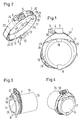
- FIG. 2 is a perspective view of a hose clamp
- FIG. 3 is a perspective view showing the hose clamp mounted on a hose.
- FIG. 4 is a perspective view of the hose clamp mounted on the hose shown from different angle.
- the sheet metal bridge is arranged relative to a diametrically oppositely located section of the clamping band 2 in such a way the sheet metal bridge is located at the distance from a section where the first positioner 8 is arranged, wherein this distance is smaller than the diameter of the hose 15 on which the hose clamp 1 is to be mounted.
- the sheet metal bridge 19 is then already slightly bent outwardly, so that the sheet metal bridge 19 rests in the area of the second position 18 with a certain tension against the circumference of the hose 15 .
- the sheet metal bridge 19 has an axial protrusion 22 whose axial length corresponds proximately to the length of the protrusion of the fastening section 9 of the first positioner.
- the second positioner 18 is bent in a U-shape at the axial end of the projection 22 , so that once again two tips 23 are formed which can claw into the inner wall 14 of the hose 15 . Of the two tips 23 , only one is visible in FIG. 2 .
- the sheet metal bridge 19 has in circumferential direction on both sides of the second positioner 18 an axial stop 24 , 25 which interacts with the end face 17 of the hose 15 when the hose clamp 1 is mounted.
- the two axial stops 24 , 25 are arranged in axial direction at the same distance from the sheet metal bridge 19 as the base 26 of the U of the second positioner 18 .
- Arranged in the same axial position is also the base 10 of the first positioner 8 , so that, when the hose clamp body is pushed onto the circumference of the hose 15 , the hose clamp 1 can be supported such that altogether four positions at the end fan 17 of the hose 15 . This effectively prevents tilting of the hose clamp 1 relative to the circumferential direction of the hose 15 .
- a spring device 26 which tensions the hose clamp even when the tensioning force of the hose clamp 1 would otherwise be diminished in the case of a thermally caused diameter change.
- a spring arrangement is already known from DE 41 27 017 C1.
- diameter change is already known from DE 41 27 017 C1.
Landscapes
- Engineering & Computer Science (AREA)
- General Engineering & Computer Science (AREA)
- Mechanical Engineering (AREA)
- Clamps And Clips (AREA)
- Joints That Cut Off Fluids, And Hose Joints (AREA)
- Supports For Pipes And Cables (AREA)
- Pharmaceuticals Containing Other Organic And Inorganic Compounds (AREA)
- Plural Heterocyclic Compounds (AREA)
- Hand Tools For Fitting Together And Separating, Or Other Hand Tools (AREA)
Abstract
Description
- 1. Field of the Invention
- The present invention relates to a hose clamp with a clamping band, a clamping device and a positioning arrangement for positioning the hose clamp on a hose.
- 2. Description of the Related Art
- A hose clamp of this type is known, for example, from WO 2004/044474A1. The positioning arrangement includes a positioner which is attached to the clamping band or is integrally formed in one piece with the clamping band. The positioner has two claw-like protrusions which can be pressed into the circumferential wall of a hose.
- A hose clamp has the primary purpose of fastening the end of a hose on a connection piece. The hose is pushed onto the connection piece and the hose clamp, which advantageously has already been mounted on the hose before the hose is pushed onto the connection piece, is tensioned by actuating the tensioning device. This procedure has to be repeated relatively frequently in the manufacture of an automobile.
- Clamping of the hose clamp usually requires the use of a tool. It is advantageous in this connection if the clamping device is arranged in a certain position. In order to ensure this position, the positioning arrangement is provided which makes it possible to secure the hose clamp on the circumference of the hose in a predetermined angular position relative to the hose.
- The use of such a positioning arrangement has already made it easier to some extent to fasten a hose on a connection piece. However, the actuation of the clamping device still requires a certain skill.
- Therefore, it is the object of the present invention to simply the assembly of a hose.
- In a hose clamp of the above-described type, the above object is met by providing the positioning arrangement with at least two positioners.
- Using two positioners, it is not only possible to secure the angular position of the hose clamp and, thus, the position of the clamping device in the circumferential direction of the hose. It is also possible to adjust with greater certainty the angular position which is assumed by the clamping band relative to the circumferential direction of the hose. As a result, tilting of the hose clamp relative to the hose becomes less likely or is even avoided, so that an inaccurate tightening of the hose clamp can be prevented. The person who is mounting the hose with the hose clamp on the connection piece has to use less care in order to tighten the hose clamp in the desired manner. A non-uniform axial deformation of the material of the hose can be avoided or reduced.
- In accordance with an advantageous feature, two positioners are spaced at a distance from each other in circumferential direction which is at least 120°. In the case of such an angular distance, the risk is relatively small that the clamping band tilts relative to the circumferential direction of the hose.
- In accordance with a preferred feature, if at least one positioner is arranged, axial stops are provided on both sides of the positioner in the circumferential direction.
- This makes it possible to reliably prevent tilting of the hose clamp relative to the circumferential direction of the hose in almost all directions.
- In accordance with a preferred feature, none of the positioners is fastened fixedly in the circumferential direction and the at least one other positioner is movable relative to the clamping band in the circumferential direction. Thus, the hose clamp has a stationary positioner and a positioner which is mounted in a “floating manner”. This makes it possible that the floating positioner can remain in the same location at the hose when the clamping band is tensioned, even if the inner diameter of the clamping band is reduces. To the extent that the internal diameter of the clamping band is reduced, the floating positioner travels relative to the clamping band.
- In accordance with a preferred feature, the movable positioner is arranged on a sheet metal bridge which is arranged in the interior of the clamping band. The sheet metal bridge has several advantageous. First, the sheet metal bridge supports the positioner in the circumferential direction at two positions relative to the clamping band, so that tilting of the clamping band relative to the circumferential direction of the hose can be avoided even if the positioner is not yet arranged immediately at the clamping band. In addition, it can be ensured that the positioner can be mounted from the beginning at the correct location on the hose because the positioner may actually have a certain distance from the clamping band in the untensioned state.
- In accordance with a preferred feature, the sheet metal bridge is constructed as a spring. This makes it easier to spread the hose clamp when the hose clamp is being disassembled.
- The movable positioner is preferably formed integrally with the sheet metal bridge. This makes the manufacture simpler. For example, the positioner and the sheet metal bridge can be punched as a single piece. The sheet metal bridge is preferably arranged in an area of the clamping device. This makes it possible to use the sheet metal bridge for another purpose, namely for covering the material gap in the area of the clamping device. The two ends of the clamping band have to overlap, wherein the inner end of the clamping band is displaced on the circumferential surface of the hose when the clamping band is tensioned. If the sheet metal bridge is arranged in this area, the inner end is not displaced immediately on the material of the hose when the clamping band is tensioned, but rather the inner end can travel on the outer side of the sheet metal bridge. Accordingly, the danger that the hose is damaged by the tensioning procedure is very small.
- Another advantage is the fact that the hose clamp has a nominal dimension and a distance between the sheet metal bridge and a diametrically oppositely located section of the clamping band is smaller than the nominal dimension. This feature makes it possible that the hose clamp is already in the untensioned state of the clamping device placed on the circumference of the hose with a certain pretension. Accordingly, the hose is clamped between the sheet metal bridge and the diametrically oppositely located section of the clamping band. The clamping forces to be used for this procedure do not have to be large. They only have to be sufficient for achieving a prepositioning of the clamp.
- The various features of novelty which characterize the invention are pointed out with particularity in the claims annexed to and forming a part of the disclosure. For a better understanding of the invention, its operating advantages, specific objects attained by its use, reference should be had to the drawing and descriptive matter in which there are illustrated and described preferred embodiments of the invention.
- In the drawing:
-
FIG. 1 is a front elevational view of a hose clamp; -
FIG. 2 is a perspective view of a hose clamp; -
FIG. 3 is a perspective view showing the hose clamp mounted on a hose; and -
FIG. 4 is a perspective view of the hose clamp mounted on the hose shown from different angle. - The hose clamp 1 shown in the drawings includes a
clamping band 2 whose ends are placed one on top of the other in such a way that there is an inner end 3 and anouter end 4. The twoends 3, 4 are connected to each other through aclamping device 5. Theclamping device 5 is fixedly connected to the inner end 3 of the clamping band and includes aclamping screw 6 which is in engagement with a threadedembossment 7 on the outer side of theouter end 4 of the clamping band. By rotating the tightening screw, theouter end 4 is displaced in the circumferential direction relative to the inner end 3 of theclamping band 2. - Diametrically oppositely arranged of the
clamping device 5 is afirst positioner 8 which is connected fixedly to theclamping band 2. The positioner may be welded or glued to theclamping band 2, or may be connected by clinching or embossing theclamping band 2. It is also possible to construct thefirst positioner 8 in a single piece with theclamping band 2. - As can be seen particularly from FIGS. 2 to 4, the
first positioner 8 has a fastening section 9 extending transversely of the circumferential direction of theclamping band 2, wherein the fasting section 9 protrudes in axial direction of theclamping band 2 by a certain distance beyond the clampingband 2. The fastening section 9 is bent at the protruding end into a U-shape, so that abase 10 and aleg 11 are formed. Theleg 11 has twotips inner wall 14 of ahose 15 on acircumferential wall 16 the hose clamp is mounted. The protrusion of the fastening section 9 defines an axial distance which is assumed by the hose clamp 1 relative to theend face 17 of thehose 15. - A
second positioner 18 is arranged diametrically opposite thefirst positioner 8. Thesecond positioner 18 is constructed in one piece with asheet metal bridge 19 which is mounted on theclamping band 2 in a floating manner. In other words, thesheet metal bridge 19 has at both its ends a pair ofbent lugs clamping band 2 in such a way that thesheet metal bridge 19 can be displaced relative to theclamping band 2. The sheet metal bridge is manufactured of a resilient material, preferably of spring steel. The sheet metal bridge is arranged relative to a diametrically oppositely located section of theclamping band 2 in such a way the sheet metal bridge is located at the distance from a section where thefirst positioner 8 is arranged, wherein this distance is smaller than the diameter of thehose 15 on which the hose clamp 1 is to be mounted. In the untensioned state, thesheet metal bridge 19 is then already slightly bent outwardly, so that thesheet metal bridge 19 rests in the area of thesecond position 18 with a certain tension against the circumference of thehose 15. - The
sheet metal bridge 19 has anaxial protrusion 22 whose axial length corresponds proximately to the length of the protrusion of the fastening section 9 of the first positioner. Thesecond positioner 18 is bent in a U-shape at the axial end of theprojection 22, so that once again twotips 23 are formed which can claw into theinner wall 14 of thehose 15. Of the twotips 23, only one is visible inFIG. 2 . - The
sheet metal bridge 19 has in circumferential direction on both sides of thesecond positioner 18 anaxial stop end face 17 of thehose 15 when the hose clamp 1 is mounted. The twoaxial stops sheet metal bridge 19 as thebase 26 of the U of thesecond positioner 18. Arranged in the same axial position is also thebase 10 of thefirst positioner 8, so that, when the hose clamp body is pushed onto the circumference of thehose 15, the hose clamp 1 can be supported such that altogether four positions at theend fan 17 of thehose 15. This effectively prevents tilting of the hose clamp 1 relative to the circumferential direction of thehose 15. - The
tips hose 15, so that the preassembled hose clamp 1 remains in the position it has once assumed until the hose clamp 1 is tightened on thehose 15. - The spring or
sheet metal bridge 19 is arranged in circumferential direction in that area where thetensioning device 5 is also located. During tensioning, the inner end 3 of theclamping band 2 moves relative to theouter end 4. This movement is kept away from thecircumferential wall 16 of thehose 15 because the inner end 3 slides on the outer surface of thesheet metal bridge 19 when thehose clamp 19 is tensioned. - A movement of the two ends 3, 4 of the
clamping band 2 is possible even though thesecond position 18 is present because thesheet metal bridge 19 is mounted in a floating manner on theclamping band 2. Accordingly, theclamping band 2 can move relative to thesheet metal bridge 19. - Additionally arranged at the inner side of the
clamping band 2 is aspring device 26 which tensions the hose clamp even when the tensioning force of the hose clamp 1 would otherwise be diminished in the case of a thermally caused diameter change. Such a spring arrangement is already known from DE 41 27 017 C1. diameter change. Such a spring arrangement is already known from DE 41 27 017 C1. - When the hose clamp 1 is tensioned, the
sheet metal bridge 19 places itself around the circumference of thehose 15. Since thesheet metal bridge 19 is made of a resilient material, it reinforces the spreading of theclamping band 2 when the clamping device is released, so that the disassembly of thehose 15 from a connection piece is facilitated. - Two
positioners tips - While specific embodiments of the invention have been shown and described in detail to illustrate the inventive principles, it will be understood that the invention may be embodied otherwise without departing from such principles.
Claims (10)
Applications Claiming Priority (3)
| Application Number | Priority Date | Filing Date | Title |
|---|---|---|---|
| DE102006048336A DE102006048336B4 (en) | 2006-10-12 | 2006-10-12 | hose clamp |
| DE102006048336.7 | 2006-10-12 | ||
| DE102006048336 | 2006-10-12 |
Publications (2)
| Publication Number | Publication Date |
|---|---|
| US20080098575A1 true US20080098575A1 (en) | 2008-05-01 |
| US7761962B2 US7761962B2 (en) | 2010-07-27 |
Family
ID=38949507
Family Applications (1)
| Application Number | Title | Priority Date | Filing Date |
|---|---|---|---|
| US11/974,167 Active 2027-11-15 US7761962B2 (en) | 2006-10-12 | 2007-10-10 | Hose clamp |
Country Status (10)
| Country | Link |
|---|---|
| US (1) | US7761962B2 (en) |
| EP (1) | EP1912008B1 (en) |
| JP (1) | JP2008095960A (en) |
| CN (1) | CN101266006B (en) |
| DE (1) | DE102006048336B4 (en) |
| ES (1) | ES2624802T3 (en) |
| HU (1) | HUE032233T2 (en) |
| PL (1) | PL1912008T3 (en) |
| RS (1) | RS55902B1 (en) |
| RU (1) | RU2358181C1 (en) |
Cited By (9)
| Publication number | Priority date | Publication date | Assignee | Title |
|---|---|---|---|---|
| US20110005040A1 (en) * | 2008-03-07 | 2011-01-13 | Veritas Ag | Clamp Fitting for a Hose End |
| US20130125347A1 (en) * | 2011-11-18 | 2013-05-23 | Honeywell International Inc. | Band clamp installation markers |
| CN105423031A (en) * | 2015-12-03 | 2016-03-23 | 安徽江淮汽车股份有限公司 | Anti-loosening clamp |
| CN107743563A (en) * | 2015-06-15 | 2018-02-27 | 德国诺玛公司 | Fixture with clamping band and pre-determined bit part |
| US20180259104A1 (en) * | 2015-11-26 | 2018-09-13 | Martin Hielscher | Hose Clamp |
| US20190049047A1 (en) * | 2017-08-11 | 2019-02-14 | Tread Enterprises Ltd | Hose Clamp with Integral Claws |
| US20190186514A1 (en) * | 2017-12-20 | 2019-06-20 | Yueqing Dongbo Electromechanical Co., Ltd. | Positioning error prevention hoop |
| KR20210145411A (en) * | 2020-05-25 | 2021-12-02 | 현대자동차주식회사 | Clamp for hose and method for assembling hose using the same |
| US20240229532A1 (en) * | 2019-10-28 | 2024-07-11 | Schlage Lock Company Llc | Door operator armature connections |
Families Citing this family (21)
| Publication number | Priority date | Publication date | Assignee | Title |
|---|---|---|---|---|
| US20060170215A1 (en) * | 2002-11-29 | 2006-08-03 | Martin Cousineau | Hose clamp |
| KR100867746B1 (en) * | 2008-02-15 | 2008-11-10 | 안국인더스트리 주식회사 | Hose clamp |
| DE102008046893A1 (en) * | 2008-09-11 | 2010-03-25 | Veritas Ag | clamp fitting |
| US9084511B2 (en) | 2009-10-22 | 2015-07-21 | Bunn-O-Matic Corporation | Flexible spray head |
| FR2959294B1 (en) * | 2010-04-21 | 2012-03-30 | Delphi Tech Inc | SEAL NECKLACE |
| US9523449B2 (en) | 2011-03-22 | 2016-12-20 | Airvac, Inc. | Pipe coupling |
| US8607422B2 (en) * | 2011-03-29 | 2013-12-17 | Ford Global Technologies, Llc | Hose clamp with wrap-around hose clamp positioner |
| US8650719B2 (en) * | 2011-07-21 | 2014-02-18 | Ideal Clamp Products, Inc. | Hose clamp with flat spring liner |
| US9541226B2 (en) | 2012-01-10 | 2017-01-10 | Ford Global Technologies, Llc | Anti-rotation worm gear clamp |
| CN103016870B (en) * | 2012-04-16 | 2015-03-18 | 上海英伦帝华汽车部件有限公司 | Hoop |
| DE102014107442A1 (en) * | 2014-05-27 | 2015-12-03 | Norma Germany Gmbh | clamp |
| CN105627002A (en) * | 2014-10-29 | 2016-06-01 | 安徽中鼎胶管制品有限公司 | Worm wheel-worm hoop and rubber pipe assembly and installation method thereof |
| US10584813B2 (en) * | 2015-09-10 | 2020-03-10 | Entegris, Inc. | Anti-rotation device for hydraulic connectors |
| US10584817B2 (en) | 2015-12-28 | 2020-03-10 | Ideal Clamp Products, Inc. | Hose clamp with retaining bracket |
| DE102016109548A1 (en) * | 2016-05-24 | 2017-11-30 | Norma Germany Gmbh | hose clamp |
| DE102016115527A1 (en) * | 2016-08-22 | 2018-02-22 | Norma Germany Gmbh | hose clamp |
| DE102017110629B4 (en) | 2017-05-16 | 2021-05-20 | Norma Germany Gmbh | Positioning device for a spring band clamp |
| US10495244B2 (en) | 2017-08-20 | 2019-12-03 | Mann+Hummel Gmbh | Positionally fixed clamp and a hose or duct having a positionally fixed clamp |
| US11460132B2 (en) * | 2019-03-25 | 2022-10-04 | Ideal Clamp Products, Inc. | Locator systems and methods for hose clamps |
| CN113825937A (en) * | 2019-04-11 | 2021-12-21 | 卡莱链接技术产业贸易公告公司 | Hose Clamps |
| US12173832B2 (en) * | 2021-05-13 | 2024-12-24 | Lincoln Industries, Inc. | Clamp insulation systems and methods |
Citations (5)
| Publication number | Priority date | Publication date | Assignee | Title |
|---|---|---|---|---|
| US3365218A (en) * | 1965-01-25 | 1968-01-23 | Richard T. Denyes | Hose and clamp preassembly |
| US3407448A (en) * | 1967-03-03 | 1968-10-29 | Wittek Mfg Company | Hose clamp with hose-attaching means |
| US3454996A (en) * | 1967-09-19 | 1969-07-15 | Wittek Mfg Co | Wire hose clamps |
| US3477106A (en) * | 1968-03-22 | 1969-11-11 | Wittek Mfg Co | Hose clamp with hose attaching means |
| US4483556A (en) * | 1982-09-22 | 1984-11-20 | Dayco Corporation | Hose clamp for a wire reinforced hose |
Family Cites Families (21)
| Publication number | Priority date | Publication date | Assignee | Title |
|---|---|---|---|---|
| JPS6439906A (en) * | 1987-08-06 | 1989-02-10 | Mitsubishi Electric Corp | Sowing of plant seed and apparatus therefor |
| FR2630808B1 (en) * | 1988-04-27 | 1990-06-22 | Peugeot | CONNECTION DEVICE |
| SU1559235A1 (en) * | 1988-06-20 | 1990-04-23 | Предприятие П/Я Г-4190 | Hose clip |
| DE4127017C1 (en) | 1990-02-22 | 1992-04-23 | Rasmussen Gmbh, 6457 Maintal, De | Hose clip with clamping strip and radial spring - which is integrally formed with clamping strip lug |
| JP2561820Y2 (en) * | 1991-07-24 | 1998-02-04 | 株式会社東郷製作所 | Hose clip |
| JPH0726712B2 (en) * | 1991-08-16 | 1995-03-29 | ラスムッセン ジイエムビイエイチ | Hose clip |
| JP3080187B2 (en) | 1991-09-27 | 2000-08-21 | 東芝キヤリア株式会社 | Control device for air conditioner |
| DE4235325C1 (en) * | 1992-10-20 | 1994-03-31 | Bayerische Motoren Werke Ag | Holding part for a hose clamp |
| US5548876A (en) * | 1995-03-01 | 1996-08-27 | Hans Oetiker Ag Maschinen- Und Apparatefabrik | Lever-type clamp |
| JP4243744B2 (en) * | 1999-03-02 | 2009-03-25 | 株式会社東郷製作所 | Hose clip with positioning tool |
| RU2155292C1 (en) * | 1999-08-03 | 2000-08-27 | Открытое акционерное общество "ГАЗ" | Hose-fastening clip |
| EP1191270B1 (en) * | 2000-09-26 | 2004-11-24 | Hans Oetiker AG Maschinen- und Apparatefabrik | Hose clamp |
| DE10249474A1 (en) * | 2002-10-24 | 2004-05-13 | Rasmussen Gmbh | Connection of a clamp with a hose for prepositioning the clamp |
| US6824169B2 (en) | 2002-11-14 | 2004-11-30 | Dayco Products, Llc | Hose and clamp assembly, clamp subassembly and method |
| DE10324236A1 (en) * | 2003-02-04 | 2004-08-12 | Veritas Ag | Pipe connecting unit fits on a pipe end and has a cylindrical middle section that has a cross-sectional sleeve with a rear circular ring |
| DE10304514B4 (en) * | 2003-02-04 | 2009-04-02 | Veritas Ag | Fixing part for a hose clamp |
| US6942253B2 (en) * | 2003-04-18 | 2005-09-13 | Epicor Industries, Inc. | Locator tab and associated hose clamp |
| DE10349527B4 (en) * | 2003-10-22 | 2009-04-23 | Veritas Ag | Hose and clamp fixation for this hose |
| DE20321371U1 (en) * | 2003-10-22 | 2006-12-28 | Veritas Ag | Tubing for fixing a tubing clip comprises recesses arranged directly below the edge and on the inner side of the end of the tubing |
| DE102004006658B3 (en) * | 2004-02-11 | 2005-02-03 | Rasmussen Gmbh | Connecting clip for hose has projections on edges of rubber-elastic ring below clip band, releasable under elastic pre-stressing |
| DE202005011542U1 (en) * | 2005-07-22 | 2005-10-06 | Rasmussen Gmbh | Clamp has add-on element connected to clamping band by clinch connection which has polygonal base surface and outwards protruding forming on outer side |
-
2006
- 2006-10-12 DE DE102006048336A patent/DE102006048336B4/en active Active
-
2007
- 2007-09-26 ES ES07018886.7T patent/ES2624802T3/en active Active
- 2007-09-26 EP EP07018886.7A patent/EP1912008B1/en active Active
- 2007-09-26 PL PL07018886T patent/PL1912008T3/en unknown
- 2007-09-26 RS RS20170440A patent/RS55902B1/en unknown
- 2007-09-26 HU HUE07018886A patent/HUE032233T2/en unknown
- 2007-10-10 US US11/974,167 patent/US7761962B2/en active Active
- 2007-10-11 RU RU2007137561/06A patent/RU2358181C1/en active
- 2007-10-11 JP JP2007265426A patent/JP2008095960A/en active Pending
- 2007-10-12 CN CN2007103071935A patent/CN101266006B/en active Active
Patent Citations (5)
| Publication number | Priority date | Publication date | Assignee | Title |
|---|---|---|---|---|
| US3365218A (en) * | 1965-01-25 | 1968-01-23 | Richard T. Denyes | Hose and clamp preassembly |
| US3407448A (en) * | 1967-03-03 | 1968-10-29 | Wittek Mfg Company | Hose clamp with hose-attaching means |
| US3454996A (en) * | 1967-09-19 | 1969-07-15 | Wittek Mfg Co | Wire hose clamps |
| US3477106A (en) * | 1968-03-22 | 1969-11-11 | Wittek Mfg Co | Hose clamp with hose attaching means |
| US4483556A (en) * | 1982-09-22 | 1984-11-20 | Dayco Corporation | Hose clamp for a wire reinforced hose |
Cited By (18)
| Publication number | Priority date | Publication date | Assignee | Title |
|---|---|---|---|---|
| US8607421B2 (en) * | 2008-03-07 | 2013-12-17 | Veritas Ag | Clamp fitting for a hose end |
| US20110005040A1 (en) * | 2008-03-07 | 2011-01-13 | Veritas Ag | Clamp Fitting for a Hose End |
| US20130125347A1 (en) * | 2011-11-18 | 2013-05-23 | Honeywell International Inc. | Band clamp installation markers |
| US8819899B2 (en) * | 2011-11-18 | 2014-09-02 | Boguslaw J Fietkiewicz | Band clamp installation markers |
| CN107743563A (en) * | 2015-06-15 | 2018-02-27 | 德国诺玛公司 | Fixture with clamping band and pre-determined bit part |
| US20180156368A1 (en) * | 2015-06-15 | 2018-06-07 | Norma Germany Gmbh | Clamp having a clamp band and a pre-positioner |
| US10571056B2 (en) * | 2015-06-15 | 2020-02-25 | Norma Germany Gmbh | Clamp having a clamp band and a pre-positioner |
| US10539260B2 (en) * | 2015-11-26 | 2020-01-21 | Norma Germany Gmbh | Hose clamp |
| US20180259104A1 (en) * | 2015-11-26 | 2018-09-13 | Martin Hielscher | Hose Clamp |
| CN105423031A (en) * | 2015-12-03 | 2016-03-23 | 安徽江淮汽车股份有限公司 | Anti-loosening clamp |
| US20190049047A1 (en) * | 2017-08-11 | 2019-02-14 | Tread Enterprises Ltd | Hose Clamp with Integral Claws |
| US10627029B2 (en) * | 2017-08-11 | 2020-04-21 | Tread Enterprises Ltd. | Hose clamp with integral claws |
| US10415610B2 (en) * | 2017-12-20 | 2019-09-17 | Yueqing Dongbo Electromechanical Co., Ltd. | Positioning error prevention hoop |
| US20190186514A1 (en) * | 2017-12-20 | 2019-06-20 | Yueqing Dongbo Electromechanical Co., Ltd. | Positioning error prevention hoop |
| US20240229532A1 (en) * | 2019-10-28 | 2024-07-11 | Schlage Lock Company Llc | Door operator armature connections |
| US12577821B2 (en) * | 2019-10-28 | 2026-03-17 | Schlage Lock Company Llc | Door operator armature connections |
| KR20210145411A (en) * | 2020-05-25 | 2021-12-02 | 현대자동차주식회사 | Clamp for hose and method for assembling hose using the same |
| KR102869239B1 (en) * | 2020-05-25 | 2025-10-10 | 현대자동차주식회사 | Clamp for hose and method for assembling hose using the same |
Also Published As
| Publication number | Publication date |
|---|---|
| EP1912008A2 (en) | 2008-04-16 |
| JP2008095960A (en) | 2008-04-24 |
| CN101266006B (en) | 2011-06-08 |
| RU2358181C1 (en) | 2009-06-10 |
| DE102006048336A1 (en) | 2008-04-17 |
| EP1912008B1 (en) | 2017-03-01 |
| HUE032233T2 (en) | 2017-09-28 |
| US7761962B2 (en) | 2010-07-27 |
| EP1912008A3 (en) | 2016-05-25 |
| DE102006048336B4 (en) | 2013-07-04 |
| ES2624802T3 (en) | 2017-07-17 |
| RS55902B1 (en) | 2017-09-29 |
| CN101266006A (en) | 2008-09-17 |
| PL1912008T3 (en) | 2017-08-31 |
Similar Documents
| Publication | Publication Date | Title |
|---|---|---|
| US7761962B2 (en) | Hose clamp | |
| US7946001B2 (en) | Hose clamp | |
| US5655865A (en) | Attachment arrangement | |
| CN108700235B (en) | Profile fixture | |
| JP4582316B2 (en) | Hose clamp holding structure | |
| CN109964071B (en) | Profile fixture | |
| JPH11315981A (en) | clip | |
| JP5580446B2 (en) | Connection configuration for conical flange connection and conical flange connection | |
| US5706558A (en) | Hose clamp | |
| US7178204B2 (en) | Hose clamp and spring liner | |
| JP2019090526A (en) | Profile clamp with seal member | |
| US6854944B2 (en) | Quick mounting nut | |
| EP0775838B1 (en) | A device for fastening an object, more particularly a pipe, to a wall | |
| KR102190946B1 (en) | Hose clamp | |
| KR102691938B1 (en) | Tightening device comprising a belt and two tightening lugs added thereon | |
| JP2007016990A (en) | Hose clamp holding structure | |
| JP2006329427A (en) | Clamp, especially profile clamp or hose clamp | |
| JPH0218411Y2 (en) | ||
| RU2789362C2 (en) | Clamping device containing a tape and two clamping legs installed on it | |
| JPH0746465Y2 (en) | Single-purpose torque wrench | |
| KR101862031B1 (en) | Hose clamp | |
| JPH0631546U (en) | Furniture leg support | |
| JPH0571413U (en) | Tightening band |
Legal Events
| Date | Code | Title | Description |
|---|---|---|---|
| AS | Assignment |
Owner name: NORMA GERMANY GMBH, GERMANY Free format text: ASSIGNMENT OF ASSIGNORS INTEREST;ASSIGNORS:KRAUSS, MATHIAS;MANN, STEPHAN;RODER, GUNTER;AND OTHERS;REEL/FRAME:020545/0012;SIGNING DATES FROM 20071005 TO 20071017 Owner name: NORMA GERMANY GMBH, GERMANY Free format text: ASSIGNMENT OF ASSIGNORS INTEREST;ASSIGNORS:KRAUSS, MATHIAS;MANN, STEPHAN;RODER, GUNTER;AND OTHERS;SIGNING DATES FROM 20071005 TO 20071017;REEL/FRAME:020545/0012 |
|
| STCF | Information on status: patent grant |
Free format text: PATENTED CASE |
|
| FPAY | Fee payment |
Year of fee payment: 4 |
|
| FEPP | Fee payment procedure |
Free format text: PAYER NUMBER DE-ASSIGNED (ORIGINAL EVENT CODE: RMPN); ENTITY STATUS OF PATENT OWNER: LARGE ENTITY Free format text: PAYOR NUMBER ASSIGNED (ORIGINAL EVENT CODE: ASPN); ENTITY STATUS OF PATENT OWNER: LARGE ENTITY |
|
| MAFP | Maintenance fee payment |
Free format text: PAYMENT OF MAINTENANCE FEE, 8TH YEAR, LARGE ENTITY (ORIGINAL EVENT CODE: M1552) Year of fee payment: 8 |
|
| MAFP | Maintenance fee payment |
Free format text: PAYMENT OF MAINTENANCE FEE, 12TH YEAR, LARGE ENTITY (ORIGINAL EVENT CODE: M1553); ENTITY STATUS OF PATENT OWNER: LARGE ENTITY Year of fee payment: 12 |