US20080098574A1 - Cord Lock - Google Patents
Cord Lock Download PDFInfo
- Publication number
- US20080098574A1 US20080098574A1 US11/632,237 US63223704A US2008098574A1 US 20080098574 A1 US20080098574 A1 US 20080098574A1 US 63223704 A US63223704 A US 63223704A US 2008098574 A1 US2008098574 A1 US 2008098574A1
- Authority
- US
- United States
- Prior art keywords
- cord
- cover portion
- connecting means
- control means
- main body
- Prior art date
- Legal status (The legal status is an assumption and is not a legal conclusion. Google has not performed a legal analysis and makes no representation as to the accuracy of the status listed.)
- Abandoned
Links
- 238000005034 decoration Methods 0.000 claims abstract description 24
- 238000001746 injection moulding Methods 0.000 claims abstract description 8
- 230000003014 reinforcing effect Effects 0.000 claims description 3
- 238000004519 manufacturing process Methods 0.000 abstract description 6
- 230000003247 decreasing effect Effects 0.000 abstract description 4
- 241000254173 Coleoptera Species 0.000 description 4
- 238000005452 bending Methods 0.000 description 3
- 230000000694 effects Effects 0.000 description 2
- 238000007792 addition Methods 0.000 description 1
- 230000002542 deteriorative effect Effects 0.000 description 1
- 230000004048 modification Effects 0.000 description 1
- 238000012986 modification Methods 0.000 description 1
- 238000000926 separation method Methods 0.000 description 1
- 239000000243 solution Substances 0.000 description 1
- 238000006467 substitution reaction Methods 0.000 description 1
Images


Classifications
-
- A—HUMAN NECESSITIES
- A44—HABERDASHERY; JEWELLERY
- A44B—BUTTONS, PINS, BUCKLES, SLIDE FASTENERS, OR THE LIKE
- A44B99/00—Subject matter not provided for in other groups of this subclass
-
- F—MECHANICAL ENGINEERING; LIGHTING; HEATING; WEAPONS; BLASTING
- F16—ENGINEERING ELEMENTS AND UNITS; GENERAL MEASURES FOR PRODUCING AND MAINTAINING EFFECTIVE FUNCTIONING OF MACHINES OR INSTALLATIONS; THERMAL INSULATION IN GENERAL
- F16G—BELTS, CABLES, OR ROPES, PREDOMINANTLY USED FOR DRIVING PURPOSES; CHAINS; FITTINGS PREDOMINANTLY USED THEREFOR
- F16G11/00—Means for fastening cables or ropes to one another or to other objects; Caps or sleeves for fixing on cables or ropes
- F16G11/10—Quick-acting fastenings; Clamps holding in one direction only
- F16G11/101—Quick-acting fastenings; Clamps holding in one direction only deforming the cable by moving a part of the fastener
-
- Y—GENERAL TAGGING OF NEW TECHNOLOGICAL DEVELOPMENTS; GENERAL TAGGING OF CROSS-SECTIONAL TECHNOLOGIES SPANNING OVER SEVERAL SECTIONS OF THE IPC; TECHNICAL SUBJECTS COVERED BY FORMER USPC CROSS-REFERENCE ART COLLECTIONS [XRACs] AND DIGESTS
- Y10—TECHNICAL SUBJECTS COVERED BY FORMER USPC
- Y10T—TECHNICAL SUBJECTS COVERED BY FORMER US CLASSIFICATION
- Y10T24/00—Buckles, buttons, clasps, etc.
- Y10T24/39—Cord and rope holders
- Y10T24/3936—Pivoted part
- Y10T24/3956—Jaws locked together by cam, wedge, lever, or screw
Definitions
- the present invention relates to a cord lock for adjusting the length of a cord used in clothes or bags, and more particularly, to a cord lock having a high quality, a compact structure, and an appearance of a beetle for adjusting the length of the cord, thereby increasing convenience in use.
- cord locks for adjusting the length of a cord used in clothes or bags are widely used and have various types.
- Japanese Patent Laid-open Publication No. 2001-70012 filed Mar. 31, 2001 discloses a cord lock.
- the cord lock disclosed by Japanese Patent Laid-open Publication No. 2001-70012 comprises a cylindrical body 1 , a lock member 2 , and a pair of elastic bending pieces 3 .
- the cylindrical body 1 includes a through hole 10 formed through the side surface thereof for passing a cord, and one opened end and the other closed end 14 .
- the lock member 2 slidably moves into and is received by the cylindrical body 1 through the opened end of the cylindrical body 1 , and includes a through hole 20 in the orthogonal relation to the movement direction thereof.
- the conventional cord lock comprises a plurality of complicated components, thereby increasing production costs and deteriorating productivity, and causes a difficulty in assembling it, thereby being incapable of having an attractive appearance.
- the present invention has been made in view of the above problems, and it is an object of the present invention to provide a cord lock with a high quality, which has a compact structure to be easily manufactured, improve productivity, and be simply used, and has an appearance of a beetle.
- a cord lock for adjusting the length of a cord used in clothes or bags, comprising: a main body for receiving the cord, including a bottom cover portion, an outer cover portion and an inner portion formed on the bottom cover portion, a control space portion formed between the outer cover portion and the inner portion, and an oval-shaped first receptor hole and an oval-shaped second receptor hole respectively formed through the outer cover portion and the inner portion for passing the cord; control means for adjusting the length of the cord, which had passed through the first receptor hole and the second receptor hole of the main body, including an upper cover portion provided with a plurality of protrusions, and a control portion protruded approximately perpendicularly from the end of the upper cover portion, received by the control space portion, and provided with a third receptor hole for passing the cord; connecting means produced integrally with the control means and the main body by injection molding for integrally connecting the control means and the main body, and provided with a fourth receptor hole for passing the cord; elastic means assembled
- the cord lock comprises the main body, the control means, and the connecting means, which are produced into one integral component by injection molding, thereby having decreased production costs and improved productivity. Further, the cord lock of the present invention comprises decoration means, which serves to ornament the external appearance thereof, and is pressed by an one-touch manner so as to release the holding of the cord, thereby being capable of easily adjusting the length of the cord and increasing convenience in use.
- FIG. 1 is a plan view of a conventional cord lock
- FIG. 2 is a longitudinal-sectional view illustrating the internal structure of the conventional cord lock
- FIG. 3 is a perspective view of a cord lock in accordance with one embodiment of the present invention.
- FIG. 4 is an exploded perspective view of the cord lock in accordance with one embodiment of the present invention.
- FIG. 5 is an exploded perspective view of the cord lock, in a state in which control means is bent, in accordance with one embodiment of the present invention
- FIG. 6 is a cross-sectional view of the cord lock, in a state in which a stopper of the control means is fastened by a main body, in accordance with one embodiment of the present invention
- FIG. 7 is a cross-sectional view of the cord lock, in a state in which the length of a cord is varied, in accordance with one embodiment of the present invention.
- FIG. 8 is a longitudinal-sectional view of the cord lock, by which a cord is held, in accordance with one embodiment of the present invention.
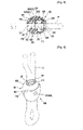
- FIG. 9 is a perspective view of a cord lock in accordance with another embodiment of the present invention.
- FIG. 3 is a perspective view of a cord lock in accordance with one embodiment of the present invention
- FIG. 4 is an exploded perspective view of the cord lock in accordance with one embodiment of the present invention
- FIG. 5 is an exploded perspective view of the cord lock, in a state in which control means is bent
- FIG. 6 is a cross-sectional view of the cord lock, in a state in which a stopper of the control means is fastened by a main body, in accordance with one embodiment of the present invention
- FIG. 7 is a cross-sectional view of the cord lock, in a state in which the length of a cord is varied, in accordance with one embodiment of the present invention
- FIG. 8 is a longitudinal-sectional view of the cord lock, by which a cord is held, in accordance with one embodiment of the present invention
- FIG. 9 is a perspective view of a cord lock in accordance with another embodiment of the present invention.
- reference numeral 100 represents a main body, for receiving a cord C used in clothes or bags, including a bottom cover portion 110 , an outer cover portion 120 and an inner portion 130 formed on the bottom cover portion 110 , a control space portion 150 formed between the outer cover portion 120 and the inner portion 130 , and an oval-shaped first receptor hole 121 and an oval-shaped second receptor hole 131 respectively formed through the outer cover portion 120 and the inner portion 130 so that the cord C passes through the first and second receptor hole 121 and 131 .
- side cover portions 140 are respectively provided on both sides of the outer cover portion 120 and the inner portion 130 , thereby defining the external appearance of the main body 100 .
- a control unit 160 for controlling the movement of decoration means, which will be described later, is provided on the upper surface of the outer cover portion 120 .
- Reference numeral 200 represents control means for adjusting the length of the cord C, which had passed through the first receptor hole 121 and the second receptor hole 131 of the main body 100 .
- the control means 200 includes an upper cover portion 210 covering the upper portion of the bottom cover portion 110 , and a control portion 220 protruded approximately perpendicularly from the end of the upper cover portion 210 and received by the control space portion 150 .
- a plurality of protrusions 211 are formed on the surface of the upper cover portion 210 of the control means 200 so that the control means 200 is assembled into the decoration means.
- An oval-shaped third receptor hole 221 for passing the cord C is formed through the control portion 220 .
- a stopper 222 which is inserted into the first receptor hole 12 of the outer cover portion 120 so that the control portion 220 is not separated from the control space portion 150 , is protruded from one surface of the control portion 220 of the control means 200 , and a concave groove 223 , through which the decoration means is firmly assembled with the control portion 220 , is formed on the other surface of the control portion 220 in opposite to the stopper 22 .
- Reference numeral 300 represents connecting means, for integrally connecting the main body 100 and the control means 200 , which is formed integrally with the main body 100 and the control means 200 by injection molding, and includes an oval-shaped fourth receptor hole 310 for passing the cord C.
- a protuberance 320 is protruded from the periphery of the fourth receptor hole 310 of the connecting means 300 , thereby allowing elastic means, which will be described later, to be firmly assembled with the connecting means 300 .
- Hinge portions 340 and 340 ′ are respectively provided on a boundary space between the connecting means 300 and the control means 200 and a boundary space between the connecting means 300 and the main body 100 .
- the hinge portions 340 and 340 ′ have thicknesses (T) larger than those of other members and widths (W) smaller than those of other members so that the connecting means 300 and the control means 200 are located at their normal positions when the control portion 220 of the control means 200 is placed in the control space portion 150 of the main body 100 and the cord C is received by the first, second, third, and fourth receptor holes 121 , 221 , 131 , and 310 .
- the hinge portions 340 and 340 ′ having large thicknesses (T) and small widths (W) are respectively provided on the boundary space between the connecting means 300 and the control means 200 and the boundary space between the connecting means 300 and the main body 100 , when the control portion 220 of the control means 200 is placed in the control space portion 150 of the main body 100 from the state as shown in FIG. 4 to the state as shown in FIG. 7 , the control portion 220 can be easily placed in the control space portion 150 .
- Reference numeral 400 represents elastic means, which is assembled with the connecting means 300 to hold, as shown in FIG. 8 , the cord (C), having passed the first receptor hole 121 and the second receptor hole 131 of the main body 100 , as shown in FIG. 7 , for applying an elastic force to the control means 200 .
- a through hole 410 is formed through the elastic means 400 so that the elastic means 400 is firmly assembled with the connecting means 300 .
- Reinforcing protuberances 420 for preventing the through hole 410 from being deformed are protruded from both sides of the through hole 410 of the elastic means 400 .
- Reference numeral 500 represents decoration means for covering the outer surfaces of the control means 200 and the connecting means 300 for ornamenting the outer appearance of the cord lock.
- the decoration means 500 includes through holes 510 , into which the protrusions 211 formed on the surface of the upper cover portion 210 are inserted by interference fit, formed through a portion thereof covering the control means 200 , and a fifth receptor hole 520 , which communicates with the fourth receptor hole 310 of the connecting means 300 , formed through a portion thereof covering the connecting means 300 .
- An insert protrusion 530 is protruded from the upper portion of the inner surface of the decoration means 500 , and is inserted into the concave groove 223 of the control means 200 so as not to separate the decoration means 500 from the control means 200 when the decoration means 500 covers the control means 200 and the connecting means 300 by inserting the protrusions 211 into the through holes 510 by interference fit.
- the protrusions 211 of the control means 200 are inserted into the through holes 510 of the decoration means 500 by interference fit, and the insert protrusion 530 of the decoration means 500 is inserted into the concave groove 223 of the control means 200 , thereby allowing the decoration means 500 to be firmly assembled with the control means 200 and the connecting means 300 without any separation.
- the number of each of the protrusions 211 and the through holes 510 is four so that the cord lock has a shape of a beetle.
- the numbers of the protrusions 211 and the through holes 510 do not limited thereto. That is, as shown in FIG. 9 , the number of each of the protrusions 211 and the through holes 510 may be one. Accordingly, the present invention is not limited to the numbers and shapes of the protrusions 211 and the through holes 510 .
- the main body 100 , the control means 200 , and the connecting means 300 are produced into one integral component by injection molding the cord lock of the present invention has decreased production costs and improved productivity.
- the cord lock of the present invention is easily assembled by anyone.
- the cord lock of the present invention has an appearance of a beetle by inserting the protrusions 211 formed on the upper cover portion 210 of the control means 200 into the through holes 510 of the decoration means 500 by the interference fit, thereby having an attractive appearance while having a high quality.
- the protuberance 320 which is protruded from the connecting means 300 , is inserted into the elastic means 400 when the elastic means 400 is assembled with the connecting means 300 , thereby being capable of firmly assembling the elastic means 400 with the connecting means 300 .
- the reinforcing protuberances 420 are protruded from both sides of the through hole 410 of the elastic means 400 , thereby increasing the endurance of the elastic means 400 without any deformation.
- the control means 200 is elevated by the elastic force of the elastic means 400 , as shown in FIG. 8 , thereby easily controlling the length of the cord C by an one-touch manner when a user wants to adjust the length of the cord C, which was held by the cord lock of the present invention.
- the third receptor hole 221 of the control means 200 coincides with the first and second receptor holes 121 and 131 of the main body 100 , as shown in FIG. 7 , thereby being capable of easily adjusting the length of the cord C.
- the control unit 160 of the main body 100 contacts the surface of the decoration means 500 , thereby being capable of more easily and efficiently adjusting the length of the cord C.
- the present invention provides a cord lock comprising a main body, control means, and connecting means, which are produced into one integral component by injection molding thereby having decreased production costs and improved productivity.
- the cord lock of the present invention comprises decoration means, which serves to ornament the external appearance thereof, and is pressed by an one-touch manner so as to release the holding of a cord, thereby being capable of easily adjusting the length of the cord and increasing convenience in use.
Landscapes
- Engineering & Computer Science (AREA)
- General Engineering & Computer Science (AREA)
- Mechanical Engineering (AREA)
- Purses, Travelling Bags, Baskets, Or Suitcases (AREA)
- Adornments (AREA)
Abstract
A cord lock for adjusting the length of a cord used in clothes or bags, including: a main body for receiving the cord, including a bottom cover portion, an outer cover portion and an inner portion formed on the bottom cover portion, a control space portion formed between the outer cover portion and the inner portion, and an oval-shaped first receptor hole and an oval-shaped second receptor hole respectively formed through the outer cover portion and the inner portion for passing the cord; control means for adjusting the length of the cord, which had passed through the first receptor hole and the second receptor hole of the main body, including an upper cover portion provided with a plurality of protrusions, and a control portion protruded approximately perpendicularly from the end of the upper cover portion, received by the control space portion, and provided with a third receptor hole for passing the cord; connecting means produced integrally with the control means and the main body by injection molding for integrally connecting the control means and the main body, and provided with a fourth receptor hole for passing the cord; elastic means assembled with the connecting means to hold the cord, having passed through the first receptor hole and the second receptor hole of the main body, for applying an elastic force to the control means, and provided with a through hole, the outer circumference of which contacts a protuberance of the connecting means, so that the elastic means is firmly assembled with the connecting means; and decoration means for covering the outer surfaces of the control means and the connecting means to ornament the outer appearance of the cord lock, and including through holes, into which the protrusions formed on the surface of the upper cover portion of the control means are inserted by interference fit, and a fifth receptor hole, formed through a portion thereof covering the connecting means, which communicates with the fourth receptor hole of the connecting means. The cord lock includes the main body, the control means, and the connecting means, which are produced into one integral component by injection molding, thereby having decreased production costs and improved productivity. Further, the cord lock comprises decoration means, which serves to ornament the external appearance thereof, and is pressed by an one-touch manner so as to release the holding of the cord, thereby being capable of easily adjusting the length of the cord and increasing convenience in use.
Description
- The present invention relates to a cord lock for adjusting the length of a cord used in clothes or bags, and more particularly, to a cord lock having a high quality, a compact structure, and an appearance of a beetle for adjusting the length of the cord, thereby increasing convenience in use.
- Generally, cord locks for adjusting the length of a cord used in clothes or bags are widely used and have various types.
- For example, Japanese Patent Laid-open Publication No. 2001-70012 filed Mar. 31, 2001 discloses a cord lock.
- As shown in
FIGS. 1 and 2 , the cord lock disclosed by Japanese Patent Laid-open Publication No. 2001-70012 comprises acylindrical body 1, a lock member 2, and a pair of elastic bending pieces 3. Thecylindrical body 1 includes a throughhole 10 formed through the side surface thereof for passing a cord, and one opened end and the other closed end 14. The lock member 2 slidably moves into and is received by thecylindrical body 1 through the opened end of thecylindrical body 1, and includes a throughhole 20 in the orthogonal relation to the movement direction thereof. Lower ends of the elastic bending pieces 3 contact the closed end 14 of thecylindrical body 1, and apply an elastic force in the direction of protruding the lock member 2, in a pressed position in which the throughhole 20 of the lock member 2 coincides with the throughhole 10 of thecylindrical body 1 so that the cord passes through the throughholes cylindrical body 1. - Since the above-described conventional cord lock, which is disclosed by Japanese Patent Laid-open Publication No. 2001-70012, comprises the
cylindrical body 1, the lock member 2, and a pair of the elastic bending pieces 3, such a conventional cord lock has a complicated structure, thereby having increased production costs and deteriorated productivity. - In case that the cord is not accommodated by the through
hole 10 of thecylindrical body 1 and the throughhole 20 of the lock member 2, thecylindrical body 1 and the lock member 2 are separated from each other, thereby causing a possibility in missing them and a difficulty in assembling the cord lock. - That is, the conventional cord lock comprises a plurality of complicated components, thereby increasing production costs and deteriorating productivity, and causes a difficulty in assembling it, thereby being incapable of having an attractive appearance.
- Therefore, the present invention has been made in view of the above problems, and it is an object of the present invention to provide a cord lock with a high quality, which has a compact structure to be easily manufactured, improve productivity, and be simply used, and has an appearance of a beetle.
- In accordance with the present invention, the above and other objects can be accomplished by the provision of a cord lock for adjusting the length of a cord used in clothes or bags, comprising: a main body for receiving the cord, including a bottom cover portion, an outer cover portion and an inner portion formed on the bottom cover portion, a control space portion formed between the outer cover portion and the inner portion, and an oval-shaped first receptor hole and an oval-shaped second receptor hole respectively formed through the outer cover portion and the inner portion for passing the cord; control means for adjusting the length of the cord, which had passed through the first receptor hole and the second receptor hole of the main body, including an upper cover portion provided with a plurality of protrusions, and a control portion protruded approximately perpendicularly from the end of the upper cover portion, received by the control space portion, and provided with a third receptor hole for passing the cord; connecting means produced integrally with the control means and the main body by injection molding for integrally connecting the control means and the main body, and provided with a fourth receptor hole for passing the cord; elastic means assembled with the connecting means to hold the cord, having passed through the first receptor hole and the second receptor hole of the main body, for applying an elastic force to the control means, and provided with a through hole, the outer circumference of which contacts a protuberance of the connecting means, so that the elastic means is firmly assembled with the connecting means; and decoration means for covering the outer surfaces of the control means and the connecting means to ornament the outer appearance of the cord lock, and including through holes, into which the protrusions formed on the surface of the upper cover portion of the control means are inserted by interference fit, and a fifth receptor hole, formed through a portion thereof covering the connecting means, which communicates with the fourth receptor hole of the connecting means.
- The cord lock comprises the main body, the control means, and the connecting means, which are produced into one integral component by injection molding, thereby having decreased production costs and improved productivity. Further, the cord lock of the present invention comprises decoration means, which serves to ornament the external appearance thereof, and is pressed by an one-touch manner so as to release the holding of the cord, thereby being capable of easily adjusting the length of the cord and increasing convenience in use.
- The above and other objects, features and other advantages of the present invention will be more clearly understood from the following detailed description taken in conjunction with the accompanying drawings, in which:
-
FIG. 1 is a plan view of a conventional cord lock; -
FIG. 2 is a longitudinal-sectional view illustrating the internal structure of the conventional cord lock; -
FIG. 3 is a perspective view of a cord lock in accordance with one embodiment of the present invention; -
FIG. 4 is an exploded perspective view of the cord lock in accordance with one embodiment of the present invention; -
FIG. 5 is an exploded perspective view of the cord lock, in a state in which control means is bent, in accordance with one embodiment of the present invention; -
FIG. 6 is a cross-sectional view of the cord lock, in a state in which a stopper of the control means is fastened by a main body, in accordance with one embodiment of the present invention; -
FIG. 7 is a cross-sectional view of the cord lock, in a state in which the length of a cord is varied, in accordance with one embodiment of the present invention; -
FIG. 8 is a longitudinal-sectional view of the cord lock, by which a cord is held, in accordance with one embodiment of the present invention; and -
FIG. 9 is a perspective view of a cord lock in accordance with another embodiment of the present invention. - Now, preferred embodiments of the present invention will be described in detail with reference to the annexed drawings.
-
FIG. 3 is a perspective view of a cord lock in accordance with one embodiment of the present invention,FIG. 4 is an exploded perspective view of the cord lock in accordance with one embodiment of the present invention,FIG. 5 is an exploded perspective view of the cord lock, in a state in which control means is bent, in accordance with one embodiment of the present invention,FIG. 6 is a cross-sectional view of the cord lock, in a state in which a stopper of the control means is fastened by a main body, in accordance with one embodiment of the present invention,FIG. 7 is a cross-sectional view of the cord lock, in a state in which the length of a cord is varied, in accordance with one embodiment of the present invention,FIG. 8 is a longitudinal-sectional view of the cord lock, by which a cord is held, in accordance with one embodiment of the present invention, andFIG. 9 is a perspective view of a cord lock in accordance with another embodiment of the present invention. - With reference to
FIGS. 3 to 9 ,reference numeral 100 represents a main body, for receiving a cord C used in clothes or bags, including abottom cover portion 110, anouter cover portion 120 and aninner portion 130 formed on thebottom cover portion 110, acontrol space portion 150 formed between theouter cover portion 120 and theinner portion 130, and an oval-shapedfirst receptor hole 121 and an oval-shapedsecond receptor hole 131 respectively formed through theouter cover portion 120 and theinner portion 130 so that the cord C passes through the first andsecond receptor hole - Further,
side cover portions 140 are respectively provided on both sides of theouter cover portion 120 and theinner portion 130, thereby defining the external appearance of themain body 100. Acontrol unit 160 for controlling the movement of decoration means, which will be described later, is provided on the upper surface of theouter cover portion 120. -
Reference numeral 200 represents control means for adjusting the length of the cord C, which had passed through thefirst receptor hole 121 and thesecond receptor hole 131 of themain body 100. The control means 200 includes anupper cover portion 210 covering the upper portion of thebottom cover portion 110, and acontrol portion 220 protruded approximately perpendicularly from the end of theupper cover portion 210 and received by thecontrol space portion 150. - A plurality of
protrusions 211 are formed on the surface of theupper cover portion 210 of the control means 200 so that the control means 200 is assembled into the decoration means. An oval-shapedthird receptor hole 221 for passing the cord C is formed through thecontrol portion 220. - A
stopper 222, which is inserted into the first receptor hole 12 of theouter cover portion 120 so that thecontrol portion 220 is not separated from thecontrol space portion 150, is protruded from one surface of thecontrol portion 220 of the control means 200, and aconcave groove 223, through which the decoration means is firmly assembled with thecontrol portion 220, is formed on the other surface of thecontrol portion 220 in opposite to the stopper 22. -
Reference numeral 300 represents connecting means, for integrally connecting themain body 100 and the control means 200, which is formed integrally with themain body 100 and the control means 200 by injection molding, and includes an oval-shapedfourth receptor hole 310 for passing the cord C. - A
protuberance 320 is protruded from the periphery of thefourth receptor hole 310 of the connectingmeans 300, thereby allowing elastic means, which will be described later, to be firmly assembled with the connectingmeans 300. -
Hinge portions means 300 and the control means 200 and a boundary space between the connectingmeans 300 and themain body 100. Thehinge portions connecting means 300 and the control means 200 are located at their normal positions when thecontrol portion 220 of the control means 200 is placed in thecontrol space portion 150 of themain body 100 and the cord C is received by the first, second, third, andfourth receptor holes - That is, since the
hinge portions connecting means 300 and the control means 200 and the boundary space between the connectingmeans 300 and themain body 100, when thecontrol portion 220 of thecontrol means 200 is placed in thecontrol space portion 150 of themain body 100 from the state as shown inFIG. 4 to the state as shown inFIG. 7 , thecontrol portion 220 can be easily placed in thecontrol space portion 150. -
Reference numeral 400 represents elastic means, which is assembled with theconnecting means 300 to hold, as shown inFIG. 8 , the cord (C), having passed thefirst receptor hole 121 and thesecond receptor hole 131 of themain body 100, as shown inFIG. 7 , for applying an elastic force to the control means 200. A throughhole 410, the outer circumference of which contacts theprotuberance 320 of the connectingmeans 300, is formed through theelastic means 400 so that theelastic means 400 is firmly assembled with the connectingmeans 300. - Reinforcing
protuberances 420 for preventing the throughhole 410 from being deformed are protruded from both sides of thethrough hole 410 of theelastic means 400. -
Reference numeral 500 represents decoration means for covering the outer surfaces of the control means 200 and theconnecting means 300 for ornamenting the outer appearance of the cord lock. The decoration means 500 includes throughholes 510, into which theprotrusions 211 formed on the surface of theupper cover portion 210 are inserted by interference fit, formed through a portion thereof covering the control means 200, and afifth receptor hole 520, which communicates with thefourth receptor hole 310 of the connectingmeans 300, formed through a portion thereof covering theconnecting means 300. - An
insert protrusion 530 is protruded from the upper portion of the inner surface of the decoration means 500, and is inserted into theconcave groove 223 of the control means 200 so as not to separate the decoration means 500 from the control means 200 when the decoration means 500 covers the control means 200 and theconnecting means 300 by inserting theprotrusions 211 into the throughholes 510 by interference fit. - That is, the
protrusions 211 of the control means 200 are inserted into the throughholes 510 of the decoration means 500 by interference fit, and theinsert protrusion 530 of the decoration means 500 is inserted into theconcave groove 223 of the control means 200, thereby allowing the decoration means 500 to be firmly assembled with the control means 200 and the connectingmeans 300 without any separation. - With reference to
FIGS. 3 to 8 , the number of each of theprotrusions 211 and the throughholes 510 is four so that the cord lock has a shape of a beetle. However, the numbers of theprotrusions 211 and the throughholes 510 do not limited thereto. That is, as shown inFIG. 9 , the number of each of theprotrusions 211 and the throughholes 510 may be one. Accordingly, the present invention is not limited to the numbers and shapes of theprotrusions 211 and the throughholes 510. - Hereinafter, the functions and effects of the above-described cord lock of the present invention will be described.
- Since the
main body 100, the control means 200, and the connectingmeans 300 are produced into one integral component by injection molding the cord lock of the present invention has decreased production costs and improved productivity. - Since the
control portion 220 of the control means 200 is received by thecontrol space portion 150 of themain body 100 by assembling theelastic means 400 with the connectingmeans 300 and applying a force to the control means 200 in the direction of an arrow A as shown inFIG. 6 , the cord lock of the present invention is easily assembled by anyone. - The cord lock of the present invention has an appearance of a beetle by inserting the
protrusions 211 formed on theupper cover portion 210 of the control means 200 into the throughholes 510 of the decoration means 500 by the interference fit, thereby having an attractive appearance while having a high quality. - The
protuberance 320, which is protruded from the connectingmeans 300, is inserted into theelastic means 400 when theelastic means 400 is assembled with the connectingmeans 300, thereby being capable of firmly assembling theelastic means 400 with the connectingmeans 300. - The reinforcing
protuberances 420 are protruded from both sides of thethrough hole 410 of theelastic means 400, thereby increasing the endurance of theelastic means 400 without any deformation. - The control means 200 is elevated by the elastic force of the elastic means 400, as shown in
FIG. 8 , thereby easily controlling the length of the cord C by an one-touch manner when a user wants to adjust the length of the cord C, which was held by the cord lock of the present invention. - That is, when the decoration means 500 is pressed by the one-touch manner in order to control the length of the cord C, the
third receptor hole 221 of the control means 200 coincides with the first andsecond receptor holes main body 100, as shown inFIG. 7 , thereby being capable of easily adjusting the length of the cord C. - When the decoration means 500 is pressed by the one-touch manner, the
control unit 160 of themain body 100 contacts the surface of the decoration means 500, thereby being capable of more easily and efficiently adjusting the length of the cord C. - As apparent from the above description, the present invention provides a cord lock comprising a main body, control means, and connecting means, which are produced into one integral component by injection molding thereby having decreased production costs and improved productivity. Further, the cord lock of the present invention comprises decoration means, which serves to ornament the external appearance thereof, and is pressed by an one-touch manner so as to release the holding of a cord, thereby being capable of easily adjusting the length of the cord and increasing convenience in use.
- Although the preferred embodiments of the present invention have been disclosed for illustrative purposes, those skilled in the art will appreciate that various modifications, additions and substitutions are possible, without departing from the scope and spirit of the invention as disclosed in the accompanying claims.
Claims (6)
1. A cord lock for adjusting the length of a cord used in clothes or bags, comprising:
a main body for receiving the cord, including a bottom cover portion, an outer cover portion and an inner portion formed on the bottom cover portion, a control space portion formed between the outer cover portion and the inner portion, and an oval-shaped first receptor hole and an oval-shaped second receptor hole respectively formed through the outer cover portion and the inner portion for passing the cord;
control means for adjusting the length of the cord, which had passed through the first receptor hole and the second receptor hole of the main body, including an upper cover portion provided with a plurality of protrusions, and a control portion protruded approximately perpendicularly from the end of the upper cover portion, received by the control space portion, and provided with a third receptor hole for passing the cord;
connecting means produced integrally with the control means and the main body by injection molding for integrally connecting the control means and the main body, and provided with a fourth receptor hole for passing the cord;
elastic means assembled with the connecting means to hold the cord, having passed through the first receptor hole and the second receptor hole of the main body, for applying an elastic force to the control means, and provided with a through hole, the outer circumference of which contacts a protuberance of the connecting means, so that the elastic means is firmly assembled with the connecting means; and
decoration means for covering the outer surfaces of the control means and the connecting means to ornament the outer appearance of the cord lock, and including through holes, into which the protrusions formed on the surface of the upper cover portion of the control means are inserted by interference fit, and a fifth receptor hole, which if formed through a portion thereof covering the connecting means so as to communicate with the fourth receptor hole of the connecting means.
2. The cord lock as set forth in claim 1 , wherein:
side cover portions are respectively provided on both sides of the outer cover portion and the inner portion to define the external appearance of the main body; and
a control unit for controlling the movement of the decoration means is provided on the upper surface of the outer cover portion.
3. The cord lock as set forth in claim 1 , wherein the protuberance is protruded from the periphery of the fourth receptor hole of the connecting means so that the elastic means is firmly assembled with the connecting means therethrough.
4. The cord lock as set forth in claim 1 , wherein hinge portions, which have thicknesses larger than those of other members and widths smaller than those of other members so that the connecting means and the control means are located at their normal positions when the control portion of the control means is placed in the control space portion of the main body and the cord is received by the first, second, third, and fourth receptor holes, are respectively provided on a boundary space between the connecting means and the control means and a boundary space between the connecting means and the main body.
5. The cord lock as set forth in claim 1 , wherein reinforcing protuberances for preventing the through hole from being deformed are protruded from both sides of the through hole of the elastic means.
6. The cord lock as set forth in claim 1 , wherein an insert protrusion, which is inserted into a concave groove of the control means so as not to separate the decoration means from the control means when the decoration means covers the control means and the connecting means by inserting the protrusions into the through holes by interference fit.
Applications Claiming Priority (3)
| Application Number | Priority Date | Filing Date | Title |
|---|---|---|---|
| KR1020040054094 | 2004-07-12 | ||
| KR1020040054094A KR20060005206A (en) | 2004-07-12 | 2004-07-12 | Cord lock |
| PCT/KR2004/002950 WO2006006754A1 (en) | 2004-07-12 | 2004-11-15 | Cord lock |
Publications (1)
| Publication Number | Publication Date |
|---|---|
| US20080098574A1 true US20080098574A1 (en) | 2008-05-01 |
Family
ID=35784078
Family Applications (1)
| Application Number | Title | Priority Date | Filing Date |
|---|---|---|---|
| US11/632,237 Abandoned US20080098574A1 (en) | 2004-07-12 | 2004-11-15 | Cord Lock |
Country Status (4)
| Country | Link |
|---|---|
| US (1) | US20080098574A1 (en) |
| JP (1) | JP2008505725A (en) |
| KR (1) | KR20060005206A (en) |
| WO (1) | WO2006006754A1 (en) |
Cited By (8)
| Publication number | Priority date | Publication date | Assignee | Title |
|---|---|---|---|---|
| US20100319169A1 (en) * | 2009-06-19 | 2010-12-23 | Chieh-Jen Lin | Tension cord fastener structure |
| US20140310919A1 (en) * | 2013-01-18 | 2014-10-23 | Nikhil Gupta | Crimping Bead with Plunger |
| USD773923S1 (en) * | 2014-12-22 | 2016-12-13 | Nifco Inc. | Cord lock |
| USD773924S1 (en) * | 2014-12-22 | 2016-12-13 | Nifco Inc. | Cord lock |
| US9686972B2 (en) | 2013-03-05 | 2017-06-27 | Edward G. SCOPELITIS | Fishing float and method |
| CN107205529A (en) * | 2015-01-20 | 2017-09-26 | 株式会社利富高 | Sling |
| US11172736B1 (en) * | 2020-05-14 | 2021-11-16 | Hongfujin Precision Electronics (Zhengzhou) Co., Ltd. | Locking device |
| USD954547S1 (en) * | 2019-12-17 | 2022-06-14 | Xiao Zhang | Cord fastener |
Families Citing this family (2)
| Publication number | Priority date | Publication date | Assignee | Title |
|---|---|---|---|---|
| FR2995052A1 (en) * | 2012-08-31 | 2014-03-07 | Breton Yann Le | Device for ensuring tightening of greenhouse cords and ropes that are utilized for supporting accessories, has multiple borings provided to retain anchoring nozzles, and opening finishing cord channel, where nozzles fit tightening part |
| WO2016117456A1 (en) * | 2015-01-20 | 2016-07-28 | 株式会社ニフコ | Cord lock |
Citations (4)
| Publication number | Priority date | Publication date | Assignee | Title |
|---|---|---|---|---|
| US4270491A (en) * | 1979-10-16 | 1981-06-02 | Cox Jack R | Animal leash |
| US5193252A (en) * | 1992-04-20 | 1993-03-16 | Svehaug Oswald C | Quick-release cleat |
| US6189186B1 (en) * | 1999-03-29 | 2001-02-20 | Robert O. Boden | Elastomeric cord lock with dual cord passages |
| US6305053B1 (en) * | 2000-02-01 | 2001-10-23 | John A. Galbreath | Cord lock |
Family Cites Families (6)
| Publication number | Priority date | Publication date | Assignee | Title |
|---|---|---|---|---|
| JPH0539309U (en) * | 1991-10-31 | 1993-05-28 | 吉田工業株式会社 | Cord stopper |
| JPH08173217A (en) * | 1994-12-27 | 1996-07-09 | Ykk Kk | String fixing device and method for attaching the string fixing device |
| JP3439291B2 (en) * | 1995-12-15 | 2003-08-25 | ワイケイケイ株式会社 | Tethers |
| JP3416437B2 (en) * | 1996-12-16 | 2003-06-16 | ワイケイケイ株式会社 | String end stopper |
| KR100346957B1 (en) * | 2000-05-25 | 2002-07-31 | 타이완인더스트리얼파스너코포레이션 | Cord lock |
| JP4519313B2 (en) * | 2000-12-21 | 2010-08-04 | 株式会社ニフコ | Tie fastener |
-
2004
- 2004-07-12 KR KR1020040054094A patent/KR20060005206A/en not_active Abandoned
- 2004-11-15 WO PCT/KR2004/002950 patent/WO2006006754A1/en not_active Ceased
- 2004-11-15 US US11/632,237 patent/US20080098574A1/en not_active Abandoned
- 2004-11-15 JP JP2007521388A patent/JP2008505725A/en active Pending
Patent Citations (4)
| Publication number | Priority date | Publication date | Assignee | Title |
|---|---|---|---|---|
| US4270491A (en) * | 1979-10-16 | 1981-06-02 | Cox Jack R | Animal leash |
| US5193252A (en) * | 1992-04-20 | 1993-03-16 | Svehaug Oswald C | Quick-release cleat |
| US6189186B1 (en) * | 1999-03-29 | 2001-02-20 | Robert O. Boden | Elastomeric cord lock with dual cord passages |
| US6305053B1 (en) * | 2000-02-01 | 2001-10-23 | John A. Galbreath | Cord lock |
Cited By (10)
| Publication number | Priority date | Publication date | Assignee | Title |
|---|---|---|---|---|
| US20100319169A1 (en) * | 2009-06-19 | 2010-12-23 | Chieh-Jen Lin | Tension cord fastener structure |
| US20140310919A1 (en) * | 2013-01-18 | 2014-10-23 | Nikhil Gupta | Crimping Bead with Plunger |
| US9631698B2 (en) * | 2013-01-18 | 2017-04-25 | Nikhil Gupta | Crimping bead with plunger |
| US9686972B2 (en) | 2013-03-05 | 2017-06-27 | Edward G. SCOPELITIS | Fishing float and method |
| USD773923S1 (en) * | 2014-12-22 | 2016-12-13 | Nifco Inc. | Cord lock |
| USD773924S1 (en) * | 2014-12-22 | 2016-12-13 | Nifco Inc. | Cord lock |
| CN107205529A (en) * | 2015-01-20 | 2017-09-26 | 株式会社利富高 | Sling |
| US10125845B2 (en) | 2015-01-20 | 2018-11-13 | Nifco Inc. | Cord Lock |
| USD954547S1 (en) * | 2019-12-17 | 2022-06-14 | Xiao Zhang | Cord fastener |
| US11172736B1 (en) * | 2020-05-14 | 2021-11-16 | Hongfujin Precision Electronics (Zhengzhou) Co., Ltd. | Locking device |
Also Published As
| Publication number | Publication date |
|---|---|
| KR20060005206A (en) | 2006-01-17 |
| JP2008505725A (en) | 2008-02-28 |
| WO2006006754A1 (en) | 2006-01-19 |
Similar Documents
| Publication | Publication Date | Title |
|---|---|---|
| US10398197B2 (en) | Cord lock | |
| US6170131B1 (en) | Magnetic buttons and structures thereof | |
| US20080098574A1 (en) | Cord Lock | |
| JP6659468B2 (en) | Code lock | |
| JPH08182152A (en) | Connector cover | |
| KR100380249B1 (en) | Method of operating plastic clip, and plastic clip using same method | |
| JP2981744B1 (en) | Plastic clip | |
| KR960014743B1 (en) | Fixture | |
| JPS6492Y2 (en) | ||
| KR200363097Y1 (en) | cord lock | |
| JP3140096U (en) | Zipper slider cover structure | |
| KR100230993B1 (en) | Cord closure | |
| JP2020141521A (en) | Cable guide and wire harness device | |
| JP3552315B2 (en) | headphone | |
| KR100476994B1 (en) | Hinge device | |
| JPH0715986Y2 (en) | Resin spring hinges and cases using resin spring hinges | |
| JP3506637B2 (en) | Vehicle door handle device | |
| CN221478194U (en) | Packaging box | |
| KR200315186Y1 (en) | a hairpin | |
| KR200270253Y1 (en) | The moving structure of a nose-pad | |
| KR102266883B1 (en) | Compact with Opening and Closing Structure Using Shape Deformation | |
| CN121057525A (en) | Vehicle key retention device | |
| KR200242494Y1 (en) | Hinge mounting structure of fancy button case | |
| KR200208048Y1 (en) | A key ring | |
| KR200264834Y1 (en) | Dial type lock |
Legal Events
| Date | Code | Title | Description |
|---|---|---|---|
| STCB | Information on status: application discontinuation |
Free format text: ABANDONED -- FAILURE TO RESPOND TO AN OFFICE ACTION |