US20080098506A1 - Drain cover with fluid flow enhancer - Google Patents
Drain cover with fluid flow enhancer Download PDFInfo
- Publication number
- US20080098506A1 US20080098506A1 US11/588,050 US58805006A US2008098506A1 US 20080098506 A1 US20080098506 A1 US 20080098506A1 US 58805006 A US58805006 A US 58805006A US 2008098506 A1 US2008098506 A1 US 2008098506A1
- Authority
- US
- United States
- Prior art keywords
- blades
- fluid
- drain
- vortex
- component
- Prior art date
- Legal status (The legal status is an assumption and is not a legal conclusion. Google has not performed a legal analysis and makes no representation as to the accuracy of the status listed.)
- Abandoned
Links
- 239000012530 fluid Substances 0.000 title claims abstract description 131
- 239000003623 enhancer Substances 0.000 title 1
- 230000001939 inductive effect Effects 0.000 claims abstract description 37
- XLYOFNOQVPJJNP-UHFFFAOYSA-N water Substances O XLYOFNOQVPJJNP-UHFFFAOYSA-N 0.000 claims abstract description 28
- 238000000034 method Methods 0.000 claims abstract description 8
- 238000009420 retrofitting Methods 0.000 claims abstract 2
- 230000006378 damage Effects 0.000 claims description 5
- 230000037361 pathway Effects 0.000 claims description 4
- 230000005465 channeling Effects 0.000 claims 1
- 238000010276 construction Methods 0.000 description 9
- 238000003260 vortexing Methods 0.000 description 6
- 238000001914 filtration Methods 0.000 description 5
- 230000003466 anti-cipated effect Effects 0.000 description 3
- 230000015572 biosynthetic process Effects 0.000 description 3
- 239000000463 material Substances 0.000 description 3
- 238000009428 plumbing Methods 0.000 description 3
- 206010013647 Drowning Diseases 0.000 description 2
- 208000027418 Wounds and injury Diseases 0.000 description 2
- 239000000853 adhesive Substances 0.000 description 2
- 230000001070 adhesive effect Effects 0.000 description 2
- 238000005336 cracking Methods 0.000 description 2
- 230000007423 decrease Effects 0.000 description 2
- 230000008030 elimination Effects 0.000 description 2
- 238000003379 elimination reaction Methods 0.000 description 2
- 208000014674 injury Diseases 0.000 description 2
- 238000012986 modification Methods 0.000 description 2
- 230000004048 modification Effects 0.000 description 2
- 239000011378 shotcrete Substances 0.000 description 2
- 230000009471 action Effects 0.000 description 1
- 238000005452 bending Methods 0.000 description 1
- 239000004568 cement Substances 0.000 description 1
- 238000002224 dissection Methods 0.000 description 1
- 230000002708 enhancing effect Effects 0.000 description 1
- 239000011152 fibreglass Substances 0.000 description 1
- 239000003292 glue Substances 0.000 description 1
- 238000002347 injection Methods 0.000 description 1
- 239000007924 injection Substances 0.000 description 1
- 238000001746 injection moulding Methods 0.000 description 1
- 238000007689 inspection Methods 0.000 description 1
- 239000011505 plaster Substances 0.000 description 1
- 230000002265 prevention Effects 0.000 description 1
- 238000005086 pumping Methods 0.000 description 1
- 230000009182 swimming Effects 0.000 description 1
Images


Classifications
-
- E—FIXED CONSTRUCTIONS
- E04—BUILDING
- E04H—BUILDINGS OR LIKE STRUCTURES FOR PARTICULAR PURPOSES; SWIMMING OR SPLASH BATHS OR POOLS; MASTS; FENCING; TENTS OR CANOPIES, IN GENERAL
- E04H4/00—Swimming or splash baths or pools
- E04H4/12—Devices or arrangements for circulating water, i.e. devices for removal of polluted water, cleaning baths or for water treatment
- E04H4/1209—Treatment of water for swimming pools
- E04H4/1218—Devices for removal of polluted water; Circumferential gutters
Definitions
- the invention herein disclosed relates to drains for pools, ponds, and spas. More particularly it relates to a device and method for providing a drain cover which provides anti-siphon characteristics above the drain cover to protect users of swimming pools and spas and provides improved fluid flow characteristics of fluid having traversed the drain cover and entering the underlying drain.
- Conventional pools, spas, ponds, and similar artificial water holders are conventionally formed with a drain opening on their bottoms at the lowest point on the bottom surface.
- these drain openings communicate through the cement or gunite or other material forming the pool or spa and connect the interior of the pool or spa with an underlying conduit into which water may be drained or is communicated to the filtration system to keep the water clean.
- water communicated through the drain opening will be pumped through a filter and back into the pool or spa through return lines which communicate therein.
- U.S. Pat. No. 6,209,586 (Wright) teaches a drain cover that is engageable over a drain opening that provides an overriding top surface that allows the user to adhere surface material thereon to match the surrounding surface.
- Wright's device is designed to break up water flow through the cover into many small linear flows substantially perpendicular to the center axis of the drain. This is typical of conventional drain covers which reduce suction and vortexing, inherently impeding water flow into and through the aperture opening of the underlying drain. As noted above, this decreases efficiency of the fluid flow and filtering system of the pool or spa resulting in increased energy use.
- a pool and spa drain cover which is engageable over the conventional drain opening communicating with the bottom of a pool or spa and prevents suction and vortexing of water that might injure or harm users and swimmers.
- Such a device should, however, in addition to substantially eliminating the suction and vortexing above the cover, enhance fluid flow once past the cover, to thereby enhance the fluid flow into the drain aperture and onto the filtering system.
- Such a device should also be adapted for easy engagement to new pool and spa construction, or as a retrofit to the millions of installed pool drains in the USA and throughout the world to thereby decrease energy use through enhanced fluid flow generated by the drain cover itself.
- the device herein disclosed and described provides an anti-vortex drain cover adapted to engage the drain opening communicating with the bottom of a pool or spa or other water holding component which has a drain and/or filtering system attached. Above the top surface of the device all safety requirements for suction and vortex elimination are met by the dissection of fluid flow into smaller linear flows to provide a safe environment for users of the pool or spa or other contained water body.
- the drain cover is provided with a base having a circumference adapted to engage the attaching ring or other engaging mount that interfaces between the drain cover and the underlying drain below the plaster or gunite or fiberglass surface that defines most pools and spas.
- a planar top component having a top surface and a lower surface is engaged to a mounting base by a plurality of ribs communicating between the top component and the base. In between the ribs are defined a plurality of passages which allow for water or fluid flow therebetween, to communicate with the cavity formed below the planar top component and above the underlying drain of the pool or spa and onto the filtering system. Breaking up the fluid flow traversing the cover by employing this plurality of blades creates a plurality of small liner fluid flows through the cover and into the cavity below the top component and above the underlying drain. These small liner flows thereby prevent the formation of a fluid vortex and suctional area adjacent to the top surface of the cover and the surrounding pool or spa surface when the device is operatively engaged to the drain.
- the blades are formed in a first preferred embodiment as part of the top planar component and project away from the lower surface of the top planar component toward the underlying drain.
- the blades radiate from a generally central portion of the bottom surface and curve to their distal ends adjacent to the passages formed between the ribs supporting the top component above the base.
- the top component is injection molded or otherwise formed in a unitary structure with the blades projecting from the bottom surface toward the underlying drain in a manner where each pair of blades at their distal ends is adjacent to two or three individual passages defined by the ribs.
- the two or three individualized and linear fluid flows through the passages between the ribs are induced to be become a portion of the total aggregate fluid flow vortex.
- This rotational vortex fluid flow is induced by the blades radiating from the center of the bottom surface of the drain cover.
- more blades can be employed to channelize fewer individual, or each, of the individual passages between the ribs, and such is anticipated.
- the blades projecting from the bottom surface of the top component also provide means to reinforce the central area of the top component from fracture. This is especially important when the device is employed in a pool or spa where users might kick or stand on the cover during use and a crack or other structural failure could have drastic consequences.
- a second preferred embodiment is also provided as either a retrofit to existing drains to induce a vortex fluid flow dynamic to fluid having traversed past the ribs supporting the top surface of the cover.
- This embodiment features a planar insert adapted for mounting above the underlying drain and below the overlying drain cover.
- a plurality of projecting tabs provide a means to hold the insert in position; however, other means can be used to position it properly in a sandwiched engagement.
- the central area of the insert would have blades projecting away from the generally smooth planar surface in a similar manner as noted above with each pair of blades, at their distal ends, being adjacent to one or more individual passages defined by the ribs.
- the individualized linear fluid flows through the passages between the ribs are induced by the blades to become a portion of the total aggregate fluid flow flowing in a vortex.
- more blades can be employed to channelize fewer individual fluid flows through the small passages between the ribs, and such is anticipated.
- the blades of the insert project upward away from the underlying drain in this preferred mode of the device, they would also work if projecting downward from the lower surface of the insert so long as the distal ends of the blades are aligned to capture and coerce the individual fluid flows coming from the passages between the ribs.
- An object of this invention is to provide a drain cover for a pool or spa or fountain that substantially eliminates suction and vortexing above the cover when installed with water flowing through it to protect bathers.
- Another object of this invention is to provide a drain cover that employs a series of axis-traverse blades positioned below the top surface of the drain cover and behind its supporting ribs which induce a vortex to the fluid once safely past the drain cover.
- An additional object of this invention is the provision of such a drain cover that induces such a vortex to increase fluid flow efficiency by imparting a cyclonic rotation to it in the underlying drain and filter system to save energy.
- a still further object of this invention is the provision of such a drain cover with a finned bottom surface to provide additional strength to the cover itself to resist cracking and failure during use.
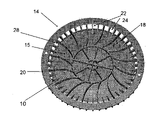
- FIG. 1 is a perspective top view of a conventional anti-vortex drain cover device showing the assembled device with the base engaged over a conventional drain aperture and underlying drain of a pool, spa, or fountain.
- FIG. 2 depicts a side view through a conventional pool cover exploded from a base mount on an underlying drain.
- FIG. 3 depicts a bottom view of one favored embodiment of the disclosed device showing the blades projecting from the bottom surface of the cover shown similarly to FIG. 1 , to coerce incoming fluid through the rib defined passages of the side surface.
- the blades may be radial, backwards curving or forwards curving depending on the alignment with the incoming water streams and vortex desired.
- FIG. 4 depicts a perspective view of another favored embodiment of the device adapted for positioning between existing conventional drain covers and underlying drains to enhance fluid flow.
- FIG. 5 depicts a perspective view of the device in an embodiment that may be affixed to the lower surface of the conventional drain covers shown in FIGS. 1-2 with adhesive or other means of attachment for retrofit or formed thereon in a new construction thereby becoming a new lower surface.
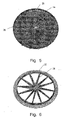
- FIG. 6 depicts an embodiment of the device having angled radially oriented blades engaged from a center portion to distal ends engaged to a mounting ring.
- FIGS. 1-6 disclose the preferred embodiments of the disclosed drain fluid flow enhancing device over the prior art of conventional anti-suction drain covers shown in FIGS. 1-2 .
- drain opening 12 or openings in the bottom of the pool or spa tends to create a suctional vortex adjacent to these drains.
- most plumbing and construction codes require that such drains are conventionally overlaid with a drain cover 14 that substantially eliminates this vortex or suction that can hold swimmers underwater.
- the drain cover 14 generally has a top component 15 having a top surface 16 and a lower surface 18 engaged to a mounting base 20 by a plurality of ribs 22 communicating between the top component 15 and the base 20 .
- a plurality of passages 24 which allow for water or fluid flow therebetween, to communicate with the cavity 26 formed below the planar top component 15 and above the underlying drain 12 or drain aperture of the pool or spa.
- the plurality of ribs 22 creates a plurality of small liner fluid flows through the passages 24 and into the cavity 26 below the top component 15 and above the underlying drain, and thereby prevents the formation of a fluid vortex and suctional area adjacent to the top surface of the cover 14 as noted.
- a plurality of blades 28 are operatively positioned in the cavity 26 under the top planar component 15 with their distal ends adjacent to and behind the ribs 22 defining the passages 24 .
- the blades may be radial and angled, backwards curving, or forwards curving, or of other configuration depending on the alignment with the incoming water streams from the passages 24 and vortex desired and the vertical placement between the drain 12 and the top component 15 . Consequently, any placement of blades 28 and the angling and curving thereof which provides a means to create a fluid vortex or cyclonic flow from incoming fluid from the passages 24 , is anticipated within the scope of this invention.
- the blades 28 are formed in a first preferred embodiment as part of the top planar component 15 and project away from the lower surface 18 of the top planar component 15 toward the underlying drain 12 . As depicted, the blades 28 radiate from a generally central portion of the cavity 26 and curve to their distal ends adjacent to the passages 24 formed between the ribs 22 . The blades 28 thus provide means to coerce the many small individual linear fluid flows from individual passages 24 to impart a vortex fluid flow to the aggregate flow of fluid resulting from the total individual fluid flows of the passages 24 . Fluid flow into the drain 12 from the cavity 26 has an efficiency-inducing vortex or cyclonic flow imparted to it.
- blades project from the bottom surface 18 toward the underlying drain in a manner where each pair of blades 28 , at their distal ends, is adjacent to two or three individual passages 24 thereby coercing the individualized linear fluid flows through the passages 24 into the vortexed fluid flow to the drain 12 .
- the blades 28 projecting from the bottom surface 18 also provide means to reinforce the top component 15 against bending or cracking if deflected by pressure.
- a second preferred embodiment of the device is provided as either a retrofit to existing drains such as in FIGS. 1-2 to induce a vortex fluid flow dynamic to fluid flow having traversed the cover.
- This embodiment features an insert style planar component 15 adapted for mounting above the underlying drain 12 and below the overlying drain cover 14 .
- a plurality of projecting tabs 32 provide a means to position the planar component 15 in the chamber 26 with the blades 28 operatively positioned to intercept and coerce the fluid flow from the passages 24 .
- the individualized linear fluid flows through the passages 24 are induced by the blades 28 to be become a portion of the total aggregate fluid flow flowing in a vortex.
- blades of the insert project upward away from the underlying drain 12 in this preferred mode of this embodiment, they would also work if projecting downward from the lower surface of the planar component 15 of the insert so long as the distal ends of the blades are aligned to capture and coerce the individual fluid flows coming from the passages 14 between the ribs 22 .
- FIG. 5 a perspective view of the device 10 using another mode of curved and radially extending blades 28 extending substantially to the center of the surface.
- This mode may be formed to the bottom surface 18 much like that of FIG. 3 to gain the improved flow, or may be formed into a base adapted for adhesion to the bottom surface 18 that may be employed to retrofit existing pool covers such as shown in FIGS. 1 and 2 .
- This mode of the device 10 provides the curved radially extending blades 28 with distal ends adapted for positioning to intercept one or preferably a plurality of the individualized fluid flows from the passages 24 much like the other modes of the device.
- the number of blades 28 is determinate of their spacing at their distal ends opposite the center of the device, and therefor the number of passages 24 from which the flow is intercepted and enhanced. If many blades 28 are formed, the device 10 could intercept each flow from each passage 24 ; however, the current preferred mode intercepts from two to four flows from passages 24 .
- FIG. 6 depicts an embodiment of the device 10 which is also adapted for retrofit of older drain covers or can be installed with new ones. While in this embodiment of the device the blades 28 do not provide reenforcement to the planar component 15 of the drain cover which is preferred, the blades 28 may be angled to impart a vortex to the water passing therebetween.
- a planar mounting ring 35 defines a perimeter edge and would be adapted to engage between the drain cover and the underlying drain 12 in a sandwiched engagement. Or, the tabs 32 of FIG. 4 might also be employed to provide support under the drain cover and above the drain 12 .
- the angled radially oriented blades 28 have their first ends engaged from a center portion and extend to distal ends engaged to the mounting ring 35 and would be positioned to engage and coerce one or preferably a plurality of the individual incoming water streams through the passages 24 into a cyclonic or vortex motion to increase water flow through the system.
- FIGS. 4-6 are shown as modes of the device 10 especially adapted for retrofit of existing anti-vortex drain covers to improve efficiency to induce cyclonic flow to the individual linear water flows through individual ribbed fluid passages on the drain cover.
- the finish depicted could be employed on the device shown in FIG. 3 where all fins 28 depend from the center point in a curved path toward the perimeter edge.
- the user would take the appropriate vortex inducing component having the plurality of blades 28 extending away from a surface of a planar component 15 with the blades 28 having first ends adjacent to a central area and distal ends positioned to terminate adjacent to one or preferably on both sides of a plurality of the 24 fluid passages.
- the spacing of the paired distal ends would be appropriate to coerce one or preferably a plurality of the individual linear flows through fluid passages 24 into a single vortex or cyclonic flow of the total aggregate fluid flow form all the passages 24 , to the underlying drain.
- the existing drain cover 14 would be dismounted and the vortex inducing component engaged to be situated between the underlying drain 12 and the drain cover 14 with the distal ends of the blades 28 aligned to corral the individual linear fluid flows from the passages 24 .
- the drain cover would then be remounted.
- the vortex inducing component would of course be adapted to the mounting and the blades 28 appropriately shaped to the size of the drain cover 14 being improved. For standard sized drains this can be done easily on a mass scale where the devices are adapted to fit the standard drain and cover engagements and the length and number of blades 28 forming pathways for the fluid flows from the passages 24 made appropriate to the task.
- the overriding concern being positioning the distal ends of the blades 28 to properly encounter and coerce fluid flows through the passages 24 into the vortex communicated to the underlying drain.
Landscapes
- Engineering & Computer Science (AREA)
- Architecture (AREA)
- Water Supply & Treatment (AREA)
- Civil Engineering (AREA)
- Structural Engineering (AREA)
- Structures Of Non-Positive Displacement Pumps (AREA)
Abstract
A fluid vortex inducing component adapted for placement between an anti-vortex drain cover of a pool or spa and the underlying drain. The device employs radially oriented blades to induce a cyclonic or vortex flow to the plurality of individual linear fluid streams traversing passages in the sidewall of the drain cover to enhance fluid flow in the underlying drain. It may be installed as a new part to existing or new drains or in a method for retrofitting existing drains a component to induce the vortex to drained water can be installed.
Description
- The invention herein disclosed relates to drains for pools, ponds, and spas. More particularly it relates to a device and method for providing a drain cover which provides anti-siphon characteristics above the drain cover to protect users of swimming pools and spas and provides improved fluid flow characteristics of fluid having traversed the drain cover and entering the underlying drain.
- Conventional pools, spas, ponds, and similar artificial water holders are conventionally formed with a drain opening on their bottoms at the lowest point on the bottom surface. Generally, these drain openings communicate through the cement or gunite or other material forming the pool or spa and connect the interior of the pool or spa with an underlying conduit into which water may be drained or is communicated to the filtration system to keep the water clean. Typically water communicated through the drain opening will be pumped through a filter and back into the pool or spa through return lines which communicate therein.
- The constant circulation of water through the drain opening or openings in the bottom of the pool or spa tends to create a suctional vortex adjacent to these drains. In order to prevent injury or worse yet, drowning, most plumbing and safety codes require that such drains are conventionally overlaid with a cover that substantially eliminates this vortex action.
- Unfortunately, most such covers tend to be utilitarian and not pleasing to the eye. In order to meed conventional plumbing and building and other applicable code requirements for vortex prevention, anti-vortex drains and covers have been developed which feature water flow characteristics that also tend to substantially eliminate the suction and vortex formation above the mounted drain cover. However, the structures which provide the vortex elimination in existing drain covers also impede water flow into the underlying drain below the drain cover once the water has traversed the drain cover.
- Consequently, because of the great attention paid to eliminate water suction and vortexing adjacent to pool and spa drains, water flow in the drain itself continues to be impeded thereby requiring additional pumping of the fluid with increased energy use resulting in reduced efficiency of the system.
- U.S. Pat. No. 6,209,586 (Wright) teaches a drain cover that is engageable over a drain opening that provides an overriding top surface that allows the user to adhere surface material thereon to match the surrounding surface. However, Wright's device is designed to break up water flow through the cover into many small linear flows substantially perpendicular to the center axis of the drain. This is typical of conventional drain covers which reduce suction and vortexing, inherently impeding water flow into and through the aperture opening of the underlying drain. As noted above, this decreases efficiency of the fluid flow and filtering system of the pool or spa resulting in increased energy use.
- U.S. Pat. No. 3,378,758 (Jacuzzi) discloses a similar anti-vortex type cover which prevents the suction and vortexing that could injure or harm swimmers. However, Jacuzzi too lacks any provision to enhance the fluid flow once it has traversed the drain cover.
- As such, there is an ongoing need for a pool and spa drain cover which is engageable over the conventional drain opening communicating with the bottom of a pool or spa and prevents suction and vortexing of water that might injure or harm users and swimmers. Such a device should, however, in addition to substantially eliminating the suction and vortexing above the cover, enhance fluid flow once past the cover, to thereby enhance the fluid flow into the drain aperture and onto the filtering system. Such a device should also be adapted for easy engagement to new pool and spa construction, or as a retrofit to the millions of installed pool drains in the USA and throughout the world to thereby decrease energy use through enhanced fluid flow generated by the drain cover itself.
- With respect to the above description, before explaining at least one preferred embodiment of the invention in detail, it is to be understood that the invention is not limited in its application to the details of construction and to the arrangement of the components or steps set forth in the following description or illustrated in the drawings. The various apparatus and methods of the invention are capable of other embodiments and of being practiced and carried out in various ways which will be obvious to those skilled in the art once they review this disclosure. Also, it is to be understood that the phraseology and terminology employed herein are for the purpose of description and should not be regarded as limiting.
- Therefore, those skilled in the art will appreciate that the conception upon which this disclosure is based may readily be utilized as a basis for designing of other devices, methods and systems for carrying out the several purposes of the present disclosed device. It is important, therefore, that the objects and claims be regarded as including such equivalent construction and methodology insofar as they do not depart from the spirit and scope of the present invention.
- Further objectives of this invention will be brought out in the following part of the specification wherein detailed description is for the purpose of fully disclosing the invention without placing limitations thereon.
- The device herein disclosed and described provides an anti-vortex drain cover adapted to engage the drain opening communicating with the bottom of a pool or spa or other water holding component which has a drain and/or filtering system attached. Above the top surface of the device all safety requirements for suction and vortex elimination are met by the dissection of fluid flow into smaller linear flows to provide a safe environment for users of the pool or spa or other contained water body.
- The drain cover is provided with a base having a circumference adapted to engage the attaching ring or other engaging mount that interfaces between the drain cover and the underlying drain below the plaster or gunite or fiberglass surface that defines most pools and spas.
- A planar top component having a top surface and a lower surface is engaged to a mounting base by a plurality of ribs communicating between the top component and the base. In between the ribs are defined a plurality of passages which allow for water or fluid flow therebetween, to communicate with the cavity formed below the planar top component and above the underlying drain of the pool or spa and onto the filtering system. Breaking up the fluid flow traversing the cover by employing this plurality of blades creates a plurality of small liner fluid flows through the cover and into the cavity below the top component and above the underlying drain. These small liner flows thereby prevent the formation of a fluid vortex and suctional area adjacent to the top surface of the cover and the surrounding pool or spa surface when the device is operatively engaged to the drain.
- In the cavity under the top planar component and behind the ribs are positioned a plurality of straight and angled or preferably curved blades, vanes or fins, (hereinafter blades) depending on the construction and alignment with the incoming water streams. The blades are formed in a first preferred embodiment as part of the top planar component and project away from the lower surface of the top planar component toward the underlying drain. The blades radiate from a generally central portion of the bottom surface and curve to their distal ends adjacent to the passages formed between the ribs supporting the top component above the base. These blades engage and coerce the many small individual fluid flows past the ribs from the individual passages between the ribs to a vortex or cyclonic flow of the fluid, to thereby provide a means to induce a vortex to the aggregate fluid flow resulting from the total individual fluid flows from all the individual passages. The fluid flow into the drain as such has an efficiency inducing vortex imparted to it, while the fluid flow above the drain cover still has the safety factor of anti-vortex and suction components.
- In a first preferred mode of the device, the top component is injection molded or otherwise formed in a unitary structure with the blades projecting from the bottom surface toward the underlying drain in a manner where each pair of blades at their distal ends is adjacent to two or three individual passages defined by the ribs. Thus, the two or three individualized and linear fluid flows through the passages between the ribs are induced to be become a portion of the total aggregate fluid flow vortex. This rotational vortex fluid flow is induced by the blades radiating from the center of the bottom surface of the drain cover. Of course more blades can be employed to channelize fewer individual, or each, of the individual passages between the ribs, and such is anticipated. Experimentation has found that a fluid vortex is generated to increase fluid flow in the underlying drain using the current preferred mode and also saves material for the injection molding process by using fewer blades. Of course more or fewer blades might also be employed so long as they generate a vortex style flow in the fluid flowing into the cavity below the top planar surface and past the ribs supporting it.
- Still further, the blades projecting from the bottom surface of the top component also provide means to reinforce the central area of the top component from fracture. This is especially important when the device is employed in a pool or spa where users might kick or stand on the cover during use and a crack or other structural failure could have drastic consequences.
- A second preferred embodiment is also provided as either a retrofit to existing drains to induce a vortex fluid flow dynamic to fluid having traversed past the ribs supporting the top surface of the cover. This embodiment features a planar insert adapted for mounting above the underlying drain and below the overlying drain cover. A plurality of projecting tabs provide a means to hold the insert in position; however, other means can be used to position it properly in a sandwiched engagement. In this embodiment, the central area of the insert would have blades projecting away from the generally smooth planar surface in a similar manner as noted above with each pair of blades, at their distal ends, being adjacent to one or more individual passages defined by the ribs. Thus, the individualized linear fluid flows through the passages between the ribs are induced by the blades to become a portion of the total aggregate fluid flow flowing in a vortex. Of course more blades can be employed to channelize fewer individual fluid flows through the small passages between the ribs, and such is anticipated. Further, while the blades of the insert project upward away from the underlying drain in this preferred mode of the device, they would also work if projecting downward from the lower surface of the insert so long as the distal ends of the blades are aligned to capture and coerce the individual fluid flows coming from the passages between the ribs.
- An object of this invention is to provide a drain cover for a pool or spa or fountain that substantially eliminates suction and vortexing above the cover when installed with water flowing through it to protect bathers.
- Another object of this invention is to provide a drain cover that employs a series of axis-traverse blades positioned below the top surface of the drain cover and behind its supporting ribs which induce a vortex to the fluid once safely past the drain cover.
- An additional object of this invention is the provision of such a drain cover that induces such a vortex to increase fluid flow efficiency by imparting a cyclonic rotation to it in the underlying drain and filter system to save energy.
- A still further object of this invention is the provision of such a drain cover with a finned bottom surface to provide additional strength to the cover itself to resist cracking and failure during use.
- These together with other objects and advantages which become subsequently apparent reside in the details of the construction and operation as more fully hereinafter described and claimed, reference being had to the accompanying drawings forming a part thereof, wherein like numerals refer to like parts throughout.
-
FIG. 1 is a perspective top view of a conventional anti-vortex drain cover device showing the assembled device with the base engaged over a conventional drain aperture and underlying drain of a pool, spa, or fountain. -
FIG. 2 depicts a side view through a conventional pool cover exploded from a base mount on an underlying drain. -
FIG. 3 depicts a bottom view of one favored embodiment of the disclosed device showing the blades projecting from the bottom surface of the cover shown similarly toFIG. 1 , to coerce incoming fluid through the rib defined passages of the side surface. The blades may be radial, backwards curving or forwards curving depending on the alignment with the incoming water streams and vortex desired. -
FIG. 4 depicts a perspective view of another favored embodiment of the device adapted for positioning between existing conventional drain covers and underlying drains to enhance fluid flow. -
FIG. 5 depicts a perspective view of the device in an embodiment that may be affixed to the lower surface of the conventional drain covers shown inFIGS. 1-2 with adhesive or other means of attachment for retrofit or formed thereon in a new construction thereby becoming a new lower surface. -
FIG. 6 depicts an embodiment of the device having angled radially oriented blades engaged from a center portion to distal ends engaged to a mounting ring. - Referring now to the drawings,
FIGS. 1-6 disclose the preferred embodiments of the disclosed drain fluid flow enhancing device over the prior art of conventional anti-suction drain covers shown inFIGS. 1-2 . - As noted, the constant circulation of water through the
drain opening 12 or openings in the bottom of the pool or spa tends to create a suctional vortex adjacent to these drains. In order to prevent injury or worse yet, drowning, most plumbing and construction codes require that such drains are conventionally overlaid with adrain cover 14 that substantially eliminates this vortex or suction that can hold swimmers underwater. - The drain cover 14 generally has a
top component 15 having atop surface 16 and alower surface 18 engaged to a mountingbase 20 by a plurality ofribs 22 communicating between thetop component 15 and thebase 20. In between theribs 22 are defined a plurality ofpassages 24 which allow for water or fluid flow therebetween, to communicate with thecavity 26 formed below the planartop component 15 and above theunderlying drain 12 or drain aperture of the pool or spa. The plurality ofribs 22 creates a plurality of small liner fluid flows through thepassages 24 and into thecavity 26 below thetop component 15 and above the underlying drain, and thereby prevents the formation of a fluid vortex and suctional area adjacent to the top surface of thecover 14 as noted. - In all preferred embodiments of the
device 10, a plurality ofblades 28 are operatively positioned in thecavity 26 under the topplanar component 15 with their distal ends adjacent to and behind theribs 22 defining thepassages 24. Those skilled in the art will realize the blades may be radial and angled, backwards curving, or forwards curving, or of other configuration depending on the alignment with the incoming water streams from thepassages 24 and vortex desired and the vertical placement between thedrain 12 and thetop component 15. Consequently, any placement ofblades 28 and the angling and curving thereof which provides a means to create a fluid vortex or cyclonic flow from incoming fluid from thepassages 24, is anticipated within the scope of this invention. - The
blades 28 are formed in a first preferred embodiment as part of the topplanar component 15 and project away from thelower surface 18 of the topplanar component 15 toward theunderlying drain 12. As depicted, theblades 28 radiate from a generally central portion of thecavity 26 and curve to their distal ends adjacent to thepassages 24 formed between theribs 22. Theblades 28 thus provide means to coerce the many small individual linear fluid flows fromindividual passages 24 to impart a vortex fluid flow to the aggregate flow of fluid resulting from the total individual fluid flows of thepassages 24. Fluid flow into thedrain 12 from thecavity 26 has an efficiency-inducing vortex or cyclonic flow imparted to it. - In a particularly preferred mode of the
device 10 ofFIG. 1 , blades project from thebottom surface 18 toward the underlying drain in a manner where each pair ofblades 28, at their distal ends, is adjacent to two or threeindividual passages 24 thereby coercing the individualized linear fluid flows through thepassages 24 into the vortexed fluid flow to thedrain 12. Theblades 28 projecting from thebottom surface 18 also provide means to reinforce thetop component 15 against bending or cracking if deflected by pressure. - A second preferred embodiment of the device is provided as either a retrofit to existing drains such as in
FIGS. 1-2 to induce a vortex fluid flow dynamic to fluid flow having traversed the cover. This embodiment features an insert styleplanar component 15 adapted for mounting above theunderlying drain 12 and below theoverlying drain cover 14. A plurality of projectingtabs 32 provide a means to position theplanar component 15 in thechamber 26 with theblades 28 operatively positioned to intercept and coerce the fluid flow from thepassages 24. Thus, the individualized linear fluid flows through thepassages 24 are induced by theblades 28 to be become a portion of the total aggregate fluid flow flowing in a vortex. Further, while the blades of the insert project upward away from theunderlying drain 12 in this preferred mode of this embodiment, they would also work if projecting downward from the lower surface of theplanar component 15 of the insert so long as the distal ends of the blades are aligned to capture and coerce the individual fluid flows coming from thepassages 14 between theribs 22. - There is seen in
FIG. 5 , a perspective view of thedevice 10 using another mode of curved and radially extendingblades 28 extending substantially to the center of the surface. This mode may be formed to thebottom surface 18 much like that ofFIG. 3 to gain the improved flow, or may be formed into a base adapted for adhesion to thebottom surface 18 that may be employed to retrofit existing pool covers such as shown inFIGS. 1 and 2 . This mode of thedevice 10 provides the curved radially extendingblades 28 with distal ends adapted for positioning to intercept one or preferably a plurality of the individualized fluid flows from thepassages 24 much like the other modes of the device. It may be engaged to thebottom surface 18 of the conventional cover using glue or adhesive or other means of attachment and impart the improved fluid flow to existing covers. As with all embodiments of the device, the number ofblades 28 is determinate of their spacing at their distal ends opposite the center of the device, and therefor the number ofpassages 24 from which the flow is intercepted and enhanced. Ifmany blades 28 are formed, thedevice 10 could intercept each flow from eachpassage 24; however, the current preferred mode intercepts from two to four flows frompassages 24. -
FIG. 6 depicts an embodiment of thedevice 10 which is also adapted for retrofit of older drain covers or can be installed with new ones. While in this embodiment of the device theblades 28 do not provide reenforcement to theplanar component 15 of the drain cover which is preferred, theblades 28 may be angled to impart a vortex to the water passing therebetween. A planar mountingring 35 defines a perimeter edge and would be adapted to engage between the drain cover and theunderlying drain 12 in a sandwiched engagement. Or, thetabs 32 ofFIG. 4 might also be employed to provide support under the drain cover and above thedrain 12. The angled radially orientedblades 28 have their first ends engaged from a center portion and extend to distal ends engaged to the mountingring 35 and would be positioned to engage and coerce one or preferably a plurality of the individual incoming water streams through thepassages 24 into a cyclonic or vortex motion to increase water flow through the system. - The components of
FIGS. 4-6 are shown as modes of thedevice 10 especially adapted for retrofit of existing anti-vortex drain covers to improve efficiency to induce cyclonic flow to the individual linear water flows through individual ribbed fluid passages on the drain cover. Also, the finish depicted could be employed on the device shown inFIG. 3 where allfins 28 depend from the center point in a curved path toward the perimeter edge. - In a retrofit, as a method of accomplishing this task the user would take the appropriate vortex inducing component having the plurality of
blades 28 extending away from a surface of aplanar component 15 with theblades 28 having first ends adjacent to a central area and distal ends positioned to terminate adjacent to one or preferably on both sides of a plurality of the 24 fluid passages. The spacing of the paired distal ends would be appropriate to coerce one or preferably a plurality of the individual linear flows throughfluid passages 24 into a single vortex or cyclonic flow of the total aggregate fluid flow form all thepassages 24, to the underlying drain. The existingdrain cover 14 would be dismounted and the vortex inducing component engaged to be situated between theunderlying drain 12 and thedrain cover 14 with the distal ends of theblades 28 aligned to corral the individual linear fluid flows from thepassages 24. The drain cover would then be remounted. The vortex inducing component would of course be adapted to the mounting and theblades 28 appropriately shaped to the size of thedrain cover 14 being improved. For standard sized drains this can be done easily on a mass scale where the devices are adapted to fit the standard drain and cover engagements and the length and number ofblades 28 forming pathways for the fluid flows from thepassages 24 made appropriate to the task. The overriding concern being positioning the distal ends of theblades 28 to properly encounter and coerce fluid flows through thepassages 24 into the vortex communicated to the underlying drain. - Further as noted above, the number of
blades 28 can be adjusted to form the number of pathways between the distal ends of theblades 28 to direct the number of individual fluid flows fromrespective passages 28. Currently between two and four individual flows works very well, but depending on the size of thepassages 24 and other factors, the number of individual flows fromindividual passages 24 intercepted could be changed. - Although the invention has been described with respect to particular embodiments thereof, it should be realized that various changes and modifications may be made therein without departing from the spirit and scope of the invention. While the invention as shown in the drawings and described in detail herein discloses arrangements of elements of particular construction and configuration for illustrating preferred embodiments of structure and method of operation of the present invention, it is to be understood, however, that elements of different construction and configuration and other arrangements thereof, other than those illustrated and described, may be employed in accordance with the spirit of this invention. Any and all such changes, alternations and modifications as would occur to those skilled in the art are considered to be within the scope of this invention as broadly defined in the appended claims.
- Further, the purpose of the attached abstract is to enable the U.S. Patent and Trademark Office and the public generally and especially the scientists, engineers and practitioners in the art who are not familiar with patent or legal terms or phraseology to determine quickly from a cursory inspection the nature and essence of the technical disclosure of the application. The abstract is neither intended to define the invention of the application which is measured by the claims, nor is it intended to be limiting as to the scope of the invention in any way.
Claims (21)
1. A fluid vortex inducing component adapted for positioning between a drain cover having a planar top component and a plurality of fluid passages communicating through a sidewall forming a plurality of linear fluid flows, and an underlying drain, comprising:
a plurality of blades extending from first ends adjacent to a central portion of a cavity formed between said drain cover and an engaged underlying drain, to distal ends adjacent to said fluid passages communicating through said sidewall;
said blades having width extending in the direction of a central axis of said underlying drain;
pathways formed between pairs of said blades, said pathways providing means to coerce fluid flow communicated therein from said fluid passages to a rotational fluid flow exiting toward said drain.
2. The fluid vortex inducing component of claim 1 further comprising:
said blades extending from a planar member; and
said planar member positioned between said planar top component of said drain cover and said underlying drain.
3. The fluid vortex inducing component of claim 1 further comprising:
said blades extending for said width from an engagement with a planar member, said planar member being a bottom surface of said planar top component of said drain cover.
4. The fluid vortex inducing component of claim 3 further comprising:
said blades and said planar top component being a unitary structure.
5. The fluid vortex inducing component of claim 3 further comprising:
said plurality of blades being adhesively engageable to said bottom surface of said top component.
6. The fluid vortex inducing component of claim 2 further comprising:
means for positioning said planar member adapted between said drain cover and said underlying drain and with said distal ends of said blades positioned adjacent to said fluid passages.
7. The fluid vortex inducing component of claim 6 wherein said means for positioning said planar member comprises:
a plurality of tabs extending from a circumference of said planar member; and
said tabs adapted for sandwiched engagement between a base portion of said drain cover and a mount for said base portion which surrounds a communication with said underlying drain.
8. The fluid vortex inducing component of claim 1 wherein said blades are substantially linear form said first ends to said distal ends and radially oriented around said central axis at an angle to said central axis, said radial orientation and said angle thereby inducing said vortex to a single fluid flow communicated to said drain formed of a plurality of individual fluid flows communicated from said fluid passages between pairs of said distal ends of said blades.
9. The fluid vortex inducing component of claim 1 wherein said blades are curved between their first ends and their distal ends and radially oriented around said central axis at an angle to said central axis, said radial orientation and said angle thereby inducing said vortex to a single fluid flow communicated to said drain formed of a plurality of individual fluid flows communicated from said fluid passages between pairs of said distal ends of said blades.
10. The fluid vortex inducing component of claim 2 wherein said blades are substantially straight and radially oriented at an angle to said central axis adapted induce said vortex in fluid communicated from said fluid passages;
said planar member having a mounting ring extending around a circumference of the distal ends of said blades; and
said mounting ring adapted for sandwiched engagement between a base of said said drain cover and an underlying mount for said base of drain cover.
11. The fluid vortex inducing component of claim 2 wherein said blades are substantially linear form said first ends to said distal ends and radially oriented around said central axis at an angle to said central axis, said radial orientation and said angle thereby inducing said vortex to a single fluid flow communicated to said drain formed of a plurality of individual fluid flows communicated from said fluid passages between pairs of said distal ends of said blades.
12. The fluid vortex inducing component of claim 3 wherein said blades are substantially linear from said first ends to said distal ends and radially oriented around said central axis at an angle to said central axis, said radial orientation and said angle thereby inducing said vortex to a single fluid flow communicated to said drain formed of a plurality of individual fluid flows communicated from said fluid passages between pairs of said distal ends of said blades.
13. The fluid vortex inducing component of claim 3 wherein said blades are curved between their first ends and their distal ends and radially oriented around said central axis at an angle to said central axis, said radial orientation and said angle thereby inducing said vortex to a single fluid flow communicated to said drain formed of a plurality of individual fluid flows communicated from said fluid passages between pairs of said distal ends of said blades.
14. The fluid vortex inducing component of claim 4 wherein said blades are substantially linear form said first ends to said distal ends and radially oriented around said central axis at an angle to said central axis, said radial orientation and said angle thereby inducing said vortex to a single fluid flow communicated to said drain formed of a plurality of individual fluid flows communicated from said fluid passages between pairs of said distal ends of said blades.
15. The fluid vortex inducing component of claim 4 wherein said blades are curved between their first ends and their distal ends and radially oriented around said central axis at an angle to said central axis, said radial orientation and said angle thereby inducing said vortex to a single fluid flow communicated to said drain formed of a plurality of individual fluid flows communicated from said fluid passages between pairs of said distal ends of said blades.
16. The fluid vortex inducing component of claim 5 wherein said blades are substantially linear form said first ends to said distal ends and radially oriented around said central axis at an angle to said central axis, said radial orientation and said angle thereby inducing said vortex to a single fluid flow communicated to said drain formed of a plurality of individual fluid flows communicated from said fluid passages between pairs of said distal ends of said blades.
17. The fluid vortex inducing component of claim 5 wherein said blades are curved between their first ends and their distal ends and radially oriented around said central axis at an angle to said central axis, said radial orientation and said angle thereby inducing said vortex to a single fluid flow communicated to said drain formed of a plurality of individual fluid flows communicated from said fluid passages between pairs of said distal ends of said blades.
18. The fluid vortex inducing component of claim 3 wherein said blades additionally provide means to reinforce said planar component against damage from deflection.
19. An anti-vortex drain cover for a pool and spa comprising:
a drain cover adapted for engagement to a drain underlying a pool or spa;
said drain cover having a planar top planar component supported by a plurality of ribs engaged to a base;
said top planar component having a top surface exposed to said pool when engaged to an underlying drain, and having a bottom surface opposite said top surface;
said ribs defining a plurality of individual fluid passages communicating through said sidewall;
a plurality of blades extending away from said bottom surface of said planar component;
said blades having first ends adjacent to a central portion of said bottom surface and having distal ends opposite said first ends;
said distal ends terminating adjacent to said fluid passages communicating through said sidewall;
said distal ends of said blades arranged in a plurality of pairs of similarly shaped said blades;
at least one of said passages positioned between each of said pairs; and
a rotational substantially singular fluid flow being communicated to an underlying drain formed by a channeling of a plurality of individual fluid flows communicated from said fluid passages between each of a respective of said pairs, into said singular fluid flow.
20. The fluid vortex inducing component of claim 19 further comprising:
said blades extending from said bottom surface of said planar component providing means to reinforce said planar component against deflection.
21. A method of retrofitting an anti-vortex drain cover mounted in a pool or spa over an underlying drain to induce a singular cyclonic flow form the product of individual linear water flows communicating through individual fluid passages of said drain cover using a vortex inducing component having a plurality of blades extending away from a surface of a planar component with said blades having first ends adjacent to a central portion of said planar component and distal ends terminating adjacent to said fluid passages, comprising the steps of:
dismounting the drain cover from its engagement to said underlying drain;
positioning said vortex inducing component to a mount between said drain cover and an underlying drain; and
remounting said drain cover to sandwich said vortex inducing component between said drain cover and said underlying drain.
Priority Applications (1)
| Application Number | Priority Date | Filing Date | Title |
|---|---|---|---|
| US11/588,050 US20080098506A1 (en) | 2006-10-25 | 2006-10-25 | Drain cover with fluid flow enhancer |
Applications Claiming Priority (1)
| Application Number | Priority Date | Filing Date | Title |
|---|---|---|---|
| US11/588,050 US20080098506A1 (en) | 2006-10-25 | 2006-10-25 | Drain cover with fluid flow enhancer |
Publications (1)
| Publication Number | Publication Date |
|---|---|
| US20080098506A1 true US20080098506A1 (en) | 2008-05-01 |
Family
ID=39328382
Family Applications (1)
| Application Number | Title | Priority Date | Filing Date |
|---|---|---|---|
| US11/588,050 Abandoned US20080098506A1 (en) | 2006-10-25 | 2006-10-25 | Drain cover with fluid flow enhancer |
Country Status (1)
| Country | Link |
|---|---|
| US (1) | US20080098506A1 (en) |
Cited By (13)
| Publication number | Priority date | Publication date | Assignee | Title |
|---|---|---|---|---|
| US20150230438A1 (en) * | 2012-09-06 | 2015-08-20 | Glynn Barber | Aquaponics system and method thereof |
| CN105863312A (en) * | 2016-06-11 | 2016-08-17 | 黄丽贤 | Safety outlet cover and water pool using same |
| US9540837B2 (en) | 2012-06-15 | 2017-01-10 | Olaf Mjelde | Low profile circular drain with water stop for swimming pools |
| CN106567564A (en) * | 2015-10-10 | 2017-04-19 | 上海荣威塑胶工业有限公司 | Pool apparatus |
| CN106703455A (en) * | 2015-11-17 | 2017-05-24 | 德州盛邦复合材料有限公司 | Disassembling and assembling type swimming pool drainer |
| US9822539B1 (en) * | 2015-01-09 | 2017-11-21 | Todd Krombein | High flow interchangeable drain cover assembly |
| USD851224S1 (en) * | 2017-02-27 | 2019-06-11 | Todd Krombein | Riser ring for drain covers |
| US10934730B2 (en) | 2018-01-15 | 2021-03-02 | Hayward Industries, Inc. | In-floor swimming pool drain and sump assembly |
| US11072916B2 (en) * | 2018-08-21 | 2021-07-27 | Carl D Coy | Shower drain with non-threaded throat |
| US11643832B1 (en) | 2012-06-15 | 2023-05-09 | Aquastar Pool Products, Inc. | Low profile circular drain with water stop for swimming pool and diverter for use therein |
| USD1077146S1 (en) | 2024-01-03 | 2025-05-27 | Revel Innovations, Llc | Drain strainer |
| USD1077992S1 (en) | 2024-10-24 | 2025-06-03 | Revel Innovations, Llc | Drain strainer |
| USD1081923S1 (en) | 2024-08-09 | 2025-07-01 | Aquastar Pool Products, Inc. | Adjustable return eyeball valve for flow synchronization |
Citations (15)
| Publication number | Priority date | Publication date | Assignee | Title |
|---|---|---|---|---|
| US3378858A (en) * | 1965-06-17 | 1968-04-23 | Jacuzzi Bros Inc | Drain assembly |
| US3753496A (en) * | 1971-12-20 | 1973-08-21 | E Boyd | Converging vortex apparatus for separating oil from water |
| US4429832A (en) * | 1981-10-16 | 1984-02-07 | Sheets Kerney T | Projectable lawn sprinkler |
| US4844403A (en) * | 1988-05-02 | 1989-07-04 | Carl Orser | Reusable form for storm sewer collection box inlets |
| US5427417A (en) * | 1994-05-18 | 1995-06-27 | Lechuga; Gabriel | Protective cover for use with drain pipes |
| US5860173A (en) * | 1996-12-09 | 1999-01-19 | Herring; Gregory L. | Bubble bath dispenser |
| US6209586B1 (en) * | 1999-12-01 | 2001-04-03 | James R. Wright | Aggregate retaining device for drain covers |
| US6340035B2 (en) * | 1999-12-01 | 2002-01-22 | James R. Wright | Aggregate retaining device for drain covers |
| US20020088347A1 (en) * | 2001-01-10 | 2002-07-11 | Kinsel John W. | Blade and skirt assembly for directional gas cleaning and drying system |
| US20020192028A1 (en) * | 2001-06-18 | 2002-12-19 | Raymond Carston | Composite pond apparatus |
| US6643857B1 (en) * | 2002-06-26 | 2003-11-11 | Caretaker Systems, Inc. | Decorative cover for swimming pool pop-up cleaning heads |
| US20040144328A1 (en) * | 2003-01-28 | 2004-07-29 | Bonner Ronald K. | Animal habitat and display system |
| US20070107119A1 (en) * | 2005-11-17 | 2007-05-17 | Plette Allison S | Pool drain safety devices and related methods |
| US7823538B1 (en) * | 2008-06-13 | 2010-11-02 | Merager Randall S | Hydration system for animals |
| US7857879B2 (en) * | 2006-11-13 | 2010-12-28 | Sulzer Chemtech Ag | Droplet separator |
-
2006
- 2006-10-25 US US11/588,050 patent/US20080098506A1/en not_active Abandoned
Patent Citations (16)
| Publication number | Priority date | Publication date | Assignee | Title |
|---|---|---|---|---|
| US3378858A (en) * | 1965-06-17 | 1968-04-23 | Jacuzzi Bros Inc | Drain assembly |
| US3753496A (en) * | 1971-12-20 | 1973-08-21 | E Boyd | Converging vortex apparatus for separating oil from water |
| US4429832A (en) * | 1981-10-16 | 1984-02-07 | Sheets Kerney T | Projectable lawn sprinkler |
| US4844403A (en) * | 1988-05-02 | 1989-07-04 | Carl Orser | Reusable form for storm sewer collection box inlets |
| US5427417A (en) * | 1994-05-18 | 1995-06-27 | Lechuga; Gabriel | Protective cover for use with drain pipes |
| US5860173A (en) * | 1996-12-09 | 1999-01-19 | Herring; Gregory L. | Bubble bath dispenser |
| US6557588B2 (en) * | 1999-12-01 | 2003-05-06 | Splash Pool Plastics, Inc. | Aggregate retaining device for drain covers |
| US6209586B1 (en) * | 1999-12-01 | 2001-04-03 | James R. Wright | Aggregate retaining device for drain covers |
| US6340035B2 (en) * | 1999-12-01 | 2002-01-22 | James R. Wright | Aggregate retaining device for drain covers |
| US20020088347A1 (en) * | 2001-01-10 | 2002-07-11 | Kinsel John W. | Blade and skirt assembly for directional gas cleaning and drying system |
| US20020192028A1 (en) * | 2001-06-18 | 2002-12-19 | Raymond Carston | Composite pond apparatus |
| US6643857B1 (en) * | 2002-06-26 | 2003-11-11 | Caretaker Systems, Inc. | Decorative cover for swimming pool pop-up cleaning heads |
| US20040144328A1 (en) * | 2003-01-28 | 2004-07-29 | Bonner Ronald K. | Animal habitat and display system |
| US20070107119A1 (en) * | 2005-11-17 | 2007-05-17 | Plette Allison S | Pool drain safety devices and related methods |
| US7857879B2 (en) * | 2006-11-13 | 2010-12-28 | Sulzer Chemtech Ag | Droplet separator |
| US7823538B1 (en) * | 2008-06-13 | 2010-11-02 | Merager Randall S | Hydration system for animals |
Cited By (21)
| Publication number | Priority date | Publication date | Assignee | Title |
|---|---|---|---|---|
| US11396759B2 (en) | 2012-06-15 | 2022-07-26 | Aquastar Pool Products, Inc. | Low profile circular drain with water stop for swimming pool |
| US10323429B1 (en) | 2012-06-15 | 2019-06-18 | Olaf Mjelde | Low profile circular drain with water stop for swimming pool |
| US9540837B2 (en) | 2012-06-15 | 2017-01-10 | Olaf Mjelde | Low profile circular drain with water stop for swimming pools |
| US11643832B1 (en) | 2012-06-15 | 2023-05-09 | Aquastar Pool Products, Inc. | Low profile circular drain with water stop for swimming pool and diverter for use therein |
| US11555321B1 (en) | 2012-06-15 | 2023-01-17 | Aquastar Pool Products, Inc. | Low profile circular drain with water stop for swimming pool |
| US11225806B1 (en) | 2012-06-15 | 2022-01-18 | Olaf Mjelde | Low profile circular drain with water stop for swimming pool |
| US10745926B1 (en) | 2012-06-15 | 2020-08-18 | Olaf Mjelde | Low profile circular drain with water stop for swimming pool |
| US10206377B2 (en) * | 2012-09-06 | 2019-02-19 | Glynn Barber | Aquaponics system and method thereof |
| US20150230438A1 (en) * | 2012-09-06 | 2015-08-20 | Glynn Barber | Aquaponics system and method thereof |
| US10428544B1 (en) * | 2015-01-09 | 2019-10-01 | Todd Krombein | High flow interchangeable drain cover assembly |
| US9822539B1 (en) * | 2015-01-09 | 2017-11-21 | Todd Krombein | High flow interchangeable drain cover assembly |
| CN106567564A (en) * | 2015-10-10 | 2017-04-19 | 上海荣威塑胶工业有限公司 | Pool apparatus |
| CN106703455A (en) * | 2015-11-17 | 2017-05-24 | 德州盛邦复合材料有限公司 | Disassembling and assembling type swimming pool drainer |
| CN105863312A (en) * | 2016-06-11 | 2016-08-17 | 黄丽贤 | Safety outlet cover and water pool using same |
| USD851224S1 (en) * | 2017-02-27 | 2019-06-11 | Todd Krombein | Riser ring for drain covers |
| US10934730B2 (en) | 2018-01-15 | 2021-03-02 | Hayward Industries, Inc. | In-floor swimming pool drain and sump assembly |
| US11319698B2 (en) * | 2018-08-21 | 2022-05-03 | Carl D Coy | Shower drain with a clamping collar |
| US11072916B2 (en) * | 2018-08-21 | 2021-07-27 | Carl D Coy | Shower drain with non-threaded throat |
| USD1077146S1 (en) | 2024-01-03 | 2025-05-27 | Revel Innovations, Llc | Drain strainer |
| USD1081923S1 (en) | 2024-08-09 | 2025-07-01 | Aquastar Pool Products, Inc. | Adjustable return eyeball valve for flow synchronization |
| USD1077992S1 (en) | 2024-10-24 | 2025-06-03 | Revel Innovations, Llc | Drain strainer |
Similar Documents
| Publication | Publication Date | Title |
|---|---|---|
| US20080098506A1 (en) | Drain cover with fluid flow enhancer | |
| US10428544B1 (en) | High flow interchangeable drain cover assembly | |
| US7531092B2 (en) | Pump | |
| US6817043B2 (en) | Safety swimming pool replacement drain cover apparatus and method | |
| US7594997B1 (en) | Portable skimmer, motor and pump protector for a swimming pool or hot tub | |
| US10036174B2 (en) | Pool skimmer system | |
| US8123469B2 (en) | Hydraulic pump comprising a prefilter body in two portions which may be oriented in rotation | |
| US11708701B1 (en) | Swimming pool skimmer with adjustable face | |
| US10718337B2 (en) | Self-priming dedicated water feature pump | |
| US10738494B1 (en) | Channel drain assembly | |
| EA011460B1 (en) | Kit for a counter current swimming pool | |
| KR102348400B1 (en) | The linear drainge appartus with point drainge function | |
| US20050172390A1 (en) | Pool cover drain system | |
| KR200444012Y1 (en) | Drain trap | |
| ES2330308T3 (en) | INSTALLATION PROCEDURE OF A SUCTION WITH PUMP. | |
| DK2014849T3 (en) | Surface suction for swimming pools or bathing ponds | |
| US10428543B2 (en) | Endless pool assembly | |
| GB2340767A (en) | Pond skimmer | |
| US20050254963A1 (en) | Water play pump | |
| KR100789284B1 (en) | Underwater Structure for River Fountain | |
| JP5041921B2 (en) | Drainage pump equipment | |
| EP4116521B1 (en) | Suction and filtering device for swimming pools and procedure for the installation of said suction and filtering device | |
| US10648188B1 (en) | Aggregate retaining devices for drains and drain covers | |
| US20060236447A1 (en) | Swimming pool steps having integrated spa | |
| US7306718B2 (en) | Skimmer with flexible weir gate for spas and pools |
Legal Events
| Date | Code | Title | Description |
|---|---|---|---|
| STCB | Information on status: application discontinuation |
Free format text: ABANDONED -- FAILURE TO RESPOND TO AN OFFICE ACTION |