US20080098503A1 - Accessory attachments for a welding garment - Google Patents
Accessory attachments for a welding garment Download PDFInfo
- Publication number
- US20080098503A1 US20080098503A1 US11/740,814 US74081407A US2008098503A1 US 20080098503 A1 US20080098503 A1 US 20080098503A1 US 74081407 A US74081407 A US 74081407A US 2008098503 A1 US2008098503 A1 US 2008098503A1
- Authority
- US
- United States
- Prior art keywords
- garment
- flame
- clothing
- resistant
- aramid
- Prior art date
- Legal status (The legal status is an assumption and is not a legal conclusion. Google has not performed a legal analysis and makes no representation as to the accuracy of the status listed.)
- Granted
Links
- 238000003466 welding Methods 0.000 title claims abstract description 49
- 239000011241 protective layer Substances 0.000 claims abstract description 29
- 230000000153 supplemental effect Effects 0.000 claims abstract description 5
- 230000007246 mechanism Effects 0.000 claims description 51
- 239000000463 material Substances 0.000 claims description 50
- 239000000203 mixture Substances 0.000 claims description 28
- 229920003235 aromatic polyamide Polymers 0.000 claims description 25
- 239000004744 fabric Substances 0.000 claims description 16
- 239000010410 layer Substances 0.000 claims description 16
- 239000004760 aramid Substances 0.000 claims description 15
- 229920000742 Cotton Polymers 0.000 claims description 11
- 230000001681 protective effect Effects 0.000 claims description 11
- 239000000835 fiber Substances 0.000 claims description 10
- RNFJDJUURJAICM-UHFFFAOYSA-N 2,2,4,4,6,6-hexaphenoxy-1,3,5-triaza-2$l^{5},4$l^{5},6$l^{5}-triphosphacyclohexa-1,3,5-triene Chemical compound N=1P(OC=2C=CC=CC=2)(OC=2C=CC=CC=2)=NP(OC=2C=CC=CC=2)(OC=2C=CC=CC=2)=NP=1(OC=1C=CC=CC=1)OC1=CC=CC=C1 RNFJDJUURJAICM-UHFFFAOYSA-N 0.000 claims description 9
- 239000003063 flame retardant Substances 0.000 claims description 9
- 238000000034 method Methods 0.000 claims description 9
- 239000000126 substance Substances 0.000 claims description 9
- 229920002994 synthetic fiber Polymers 0.000 claims description 9
- 239000012209 synthetic fiber Substances 0.000 claims description 9
- 239000010985 leather Substances 0.000 claims description 8
- 229920002821 Modacrylic Polymers 0.000 claims description 5
- 229920001407 Modal (textile) Polymers 0.000 claims description 5
- 229920000297 Rayon Polymers 0.000 claims description 5
- 229920006231 aramid fiber Polymers 0.000 claims description 5
- 229920002239 polyacrylonitrile Polymers 0.000 claims description 5
- 239000002964 rayon Substances 0.000 claims description 5
- 239000004677 Nylon Substances 0.000 claims description 4
- 229920001778 nylon Polymers 0.000 claims description 4
- 230000001502 supplementing effect Effects 0.000 claims 2
- 230000009286 beneficial effect Effects 0.000 description 3
- 239000002184 metal Substances 0.000 description 3
- 229920000784 Nomex Polymers 0.000 description 2
- 238000012986 modification Methods 0.000 description 2
- 230000004048 modification Effects 0.000 description 2
- 239000004763 nomex Substances 0.000 description 2
- 241001223864 Sphyraena barracuda Species 0.000 description 1
- 238000005299 abrasion Methods 0.000 description 1
- 230000003203 everyday effect Effects 0.000 description 1
- 238000006467 substitution reaction Methods 0.000 description 1
- 239000002699 waste material Substances 0.000 description 1
Images


Classifications
-
- A—HUMAN NECESSITIES
- A62—LIFE-SAVING; FIRE-FIGHTING
- A62B—DEVICES, APPARATUS OR METHODS FOR LIFE-SAVING
- A62B17/00—Protective clothing affording protection against heat or harmful chemical agents or for use at high altitudes
- A62B17/003—Fire-resistant or fire-fighters' clothes
-
- A—HUMAN NECESSITIES
- A41—WEARING APPAREL
- A41D—OUTERWEAR; PROTECTIVE GARMENTS; ACCESSORIES
- A41D13/00—Professional, industrial or sporting protective garments, e.g. surgeons' gowns or garments protecting against blows or punches
-
- A—HUMAN NECESSITIES
- A41—WEARING APPAREL
- A41D—OUTERWEAR; PROTECTIVE GARMENTS; ACCESSORIES
- A41D13/00—Professional, industrial or sporting protective garments, e.g. surgeons' gowns or garments protecting against blows or punches
- A41D13/04—Aprons; Fastening devices for aprons
-
- A—HUMAN NECESSITIES
- A41—WEARING APPAREL
- A41D—OUTERWEAR; PROTECTIVE GARMENTS; ACCESSORIES
- A41D2400/00—Functions or special features of garments
- A41D2400/70—Removability
-
- A—HUMAN NECESSITIES
- A41—WEARING APPAREL
- A41D—OUTERWEAR; PROTECTIVE GARMENTS; ACCESSORIES
- A41D2600/00—Uses of garments specially adapted for specific purposes
- A41D2600/20—Uses of garments specially adapted for specific purposes for working activities
- A41D2600/202—Welding
Definitions
- the invention relates generally to a welding garment. More specifically, the invention relates to a flame-resistant welding garment, such as a welding jacket or another article of clothing, configured to receive a supplemental flame-resistant protective layer or other accessory attachments.
- Welding garments are typically a one-piece garment, which can be bulky and likely to retain body heat. If the welding garment is not worn by an operator, then the heat, sparks, or molten metal associated with a welding procedure may injure the operator due to a lack of flame resistance of normal clothing. However, in many facilities and applications, the operator may perform welding procedures intermittently rather than continuously throughout the day. Thus, the welding garment is not continuously needed for protection. Welding procedures often occur in uncontrollable, unpredictable, or extreme weather conditions, for example, high temperature and high humidity. These weather conditions can make the existing welding garments uncomfortable or unbearable to wear. As a result, the operator may be inclined to perform the welding procedures without the proper welding garment. In addition, if the welding garment becomes overly worn, damaged, or ineffective to protect against the welding conditions, then the entire welding garment is typically replaced at a significant cost.
- a flame resistant garment may include multiple garment portions to provide different degrees of protection for welding or another application.
- the flame-resistant garment may include a base garment and one or more supplemental protective layers or garments.
- the base garment may include a jacket, a vest, a coverall, a jumpsuit, an overall, pants, trousers, a smock, a hat, a hood, or a combination thereof.
- the protective layer may include a bib or any other suitable attachment to add further flame resistance.
- the multiple garment portions may be coupled together via a snap fastener system, a hook-and-loop system, a button system, a zipper system, a buckle system, or a clip system, or a combination thereof.
- FIG. 1 illustrates a front elevational view and a back elevational view of an embodiment of a flame-resistant article of clothing, wherein the clothing includes a jacket having upper and lower portions made from first and second materials, respectively;
- FIG. 2 illustrates a front elevational view and a back elevational view of an alternate embodiment of the jacket shown in FIG. 1 ;
- FIG. 3 is a front elevational view of an embodiment of the jacket shown in FIGS. 1 and 2 , further illustrating a fastening mechanism located at an upper attachment area and a lower attachment area;
- FIG. 4 is a back elevational view of an embodiment of a flame-resistant protective layer of clothing, such as a bib, configured to couple with the jacket shown in FIGS. 1-3 ;
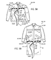
- FIG. 5A illustrates the bib of FIG. 4 removably attached to the jacket of FIGS. 1-3 at the upper attachment area;
- FIG. 5B illustrates the bib of FIG. 4 removably attached to the jacket of FIGS. 1-3 at the lower attachment area;
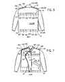
- FIG. 6 is a back elevational view of an alternate embodiment of the jacket of FIG. 1 , wherein the jacket includes a shoulder attachment region, a mid-back attachment region, and a lower waist-line attachment region;
- FIG. 7 illustrates the bib of FIG. 4 removably attached to the jacket of FIG. 6 at the shoulder attachment region
- FIG. 8 illustrates an alternate embodiment of a bib removably attached to the jacket of FIG. 6 at the mid-back attachment region, wherein the bib wraps around the entire lower portion of the jacket;
- FIG. 9A is an alternate embodiment of a jacket system illustrating a smock and a vest configuration
- FIG. 9B shows the jacket system of FIG. 9A , illustrating the smock attached to the vest;
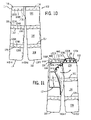
- FIG. 10 illustrates a front elevational view of an alternate embodiment of a flame-resistant article of clothing, wherein the clothing includes pants having a waist attachment section, a mid-thigh section, and a shin section;
- FIG. 11 illustrates the bib of FIG. 4 removably attached to the pants of FIG. 10 at the waist attachment section
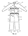
- FIG. 12 illustrates a front elevational view of an alternate embodiment of a flame-resistant article of clothing, wherein the clothing includes a jumpsuit or overalls.
- the garment may include a flame-resistant article of clothing that is configured to receive a protective layer of clothing via a fastening mechanism.
- the article of clothing may include a jacket, a vest, a coverall, a jumpsuit, an overall, pants, trousers, smock, a hat, a hood, or a combination thereof.
- the protective layer of clothing may include a bib or other accessory attachments.
- the accessory attachments provide for modularity or layering of flame-resistant material, thereby enabling the wearer to increase or decrease flame-resistant layers as desired. This is beneficial because it enables the operator to customize flame-resistant protection from one application to the next.
- the article of clothing is a welding jacket that includes a top section and a bottom section that may be made from the same or different flame-resistant materials.
- the wearer In a first operation, the wearer might be engaged in an over-head welding operation, thereby exposing his or her upper body to the heat intensive operation. Therefore, the wearer may desire more protection for the shoulder area during this operation as compared to a lower level welding operation, e.g., at a bench or in a bent over position.
- the multi-layered system enables the user to wear the article of clothing in a fitted manner which may be more comfortable than a standard protective garment that only provides “one size fits all” protection.
- embodiments of the present invention reduce the cost of flame-resistant protection by enabling the user to replace worn or abraded accessory attachments without having to replace the entire article of clothing. This may also reduce the initial cost of the article of clothing by enabling the substitution of a less expensive material given it may only need to serve as a redundant layer to the attached accessory. Therefore, the article of clothing may not only be less expensive but may also be made from a lighter weight material to provide additional comfort for the wearer when he/she is not engaged in a welding operation.
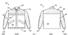
- FIG. 1 illustrates a front view 12 A and a back view 14 A of a flame-resistant article of clothing in the form of jacket 10 A.
- Welding jacket 10 A may be made from any number of materials, including leather, in whole or in part. Additionally, welding jacket may be made from flame-resistant materials that may include a chemically treated natural fabric, a chemically treated natural fabric and synthetic fiber blend, a flame-resistant synthetic fiber blend, a flame-resistant leather, or a combination thereof.
- Welding jacket 10 A includes a top section or upper portion 16 A and a bottom section or lower portion 18 A.
- Top section 16 A includes a collar 20 A, shoulder area 22 A, a left sleeve 24 , and a right sleeve 26 .
- the top section 16 A terminates at a first bottom edge or upper attachment area 28 A.
- Bottom section 18 A substantially covers the torso of the wearer and terminates in a second bottom edge or lower attachment area 30 A.
- Lower attachment area 30 A may be located at or below the waist of the person wearing the jacket, when the jacket is worn.
- top section 16 A may be made of leather and bottom section 18 A may be made of a flame-resistant cotton fabric or any other suitable material.
- Jacket 10 A may be worn by the wearer in a standard fashion, and has a vertical zipper or vertical array of buttons that crosses the top section 16 A and bottom section 18 A to enable opening or closing of jacket 10 A about the wearer. Additionally, collar 20 A may include a number of different configurations, such as a barracuda style or square edged turned down style.
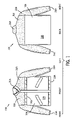
- FIG. 2 illustrates a front view 12 B and a back view 14 B of an alternate embodiment of a welding jacket 10 B.
- Welding jacket 10 B includes a top section 16 B, a bottom section 18 B, a collar 20 B, a shoulder area 22 B, a left sleeve 24 B, a right sleeve 26 B, a first bottom edge 28 B, and a second bottom edge 30 B.
- jacket 10 B may include a hat or hood attached at or near collar 20 B.
- top section 16 B and bottom section 18 B are made from a single flame-resistant material, such as a flame-resistant cotton fabric, that is suitable for jacket 10 B.
- top section 16 B and bottom section 18 B may include more than one flame-resistant material.
- the top section 16 B, the bottom section 18 B, or both may be made of a flame-resistant material including a cotton fabric impregnated with a flame retardant chemical; a vinal and polynosic rayon blend; an aramid synthetic fiber; a meta-aramid and para-aramid fiber blend; a meta-aramid, para-aramid, and modacrylic fiber blend; an oxidized polyacrylonitrile and aramid fiber blend; or a combination thereof.
- a cotton fabric impregnated with a flame retardant chemical is available from Westex Inc. in Chicago, Ill., and may be identified under the trademark INDURA.
- An exemplary embodiment of a cotton and high tenacity nylon fabric blend impregnated with a flame retardant chemical is also available from Westex Inc. and may be identified under the trademark INDURA Ultra Soft.
- Westex also provides an exemplary embodiment of a vinal and polynosic rayon blend that may be identified under the trademark Vinex.
- an exemplary embodiment of an aramid synthetic fiber is available from DuPont in Richmond, Va., and may be identified under the trademark NOMEX.
- An exemplary embodiment of a meta-aramid and para-aramid fiber blend is also available from DuPont and may be identified under the trademark NOMEX IIIA.
- DuPont also provides an exemplary embodiment of a meta-aramid, para-aramid, and modacrylic fiber blend that may be identified under the trademark Protera.
- an exemplary embodiment of an oxidized polyacrylonitrile and aramid fiber blend is available from Chapman Thermal Products in Salt Lake City, Utah, and may be identified under the trademark CarbonX.
- the flame-resistant material may include leather, such as pigskin or goatskin leather.
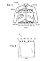
- FIG. 3 illustrates another front view 12 of the jacket 10 shown in FIGS. 1 and 2 , further illustrating a fastening mechanism located at an upper attachment area and a lower attachment area.
- FIG. 3 illustrates jacket 10 having top section 16 and bottom section 18 .
- Flame-resistant layers or flaps 32 and 38 are located at first bottom edge 28 and second bottom edge 30 , respectively. Flaps 32 , 38 may be lifted to expose a fastening mechanism located on jacket 10 .
- flaps 32 , 38 are made from a flame-resistant material and provide a protective layer to cover the fastening mechanism.
- flaps 32 , 38 protect the fastening mechanism from molten metal, sparks, or BB's originating from a weld location during a welding procedure.
- one of the contemplated embodiments of the flame-resistant garment includes male snaps 36 A, 36 B, 36 C, 40 A, 40 B, and 40 C as the fastening mechanism.
- flaps 32 , 38 helps to prevent the male snaps from becoming damaged or made inoperable as a result of refracted material that may lodge within the snaps and/or melt the snaps.
- the present embodiments are not limited to snaps, and flaps 32 , 38 may provide protection for various fastening mechanisms.
- the fastening mechanisms may include a hook-and-loop system, a button system, a zipper system, a buckle system, a clip system, a snap fastener system, or a combination system thereof.
- FIG. 4 is a back view of an embodiment of a flame-resistant protective layer of clothing or protective garment 42 in the form of a bib.
- Bib 42 is an accessory attachment having an attachment mechanism located along a top periphery of the bib.
- the attachment mechanism includes female snaps 44 A, 44 B, 44 C, 44 D, 44 E, and 44 F.
- Female snaps 44 A, 44 B, and 44 C are separated or spaced apart so that they mate with male snaps 36 A, 36 B, 36 C, located on the right side of top section 16 of jacket 10 .
- female snaps 44 D, 44 E, and 44 F are separated or spaced apart so that they mate with male snaps 36 A, 36 B, 36 C, located on the left side of top section 16 of jacket 10 .
- Bib accessory 42 may be sized to substantially or entirely cover jacket 10 about the torso of the wearer when attached to the jacket at this location.
- male snaps 40 A, 40 B, 40 C may be spaced similar to male snaps 36 A, 36 B, and 36 C, such that bib 42 can be attached at this location of jacket 10 .
- FIG. 5A illustrates bib 42 partially attached to the right side of jacket 10 at upper attachment area 28 .
- the figure shows flaps 32 lifted to expose the fastening mechanism thereby enabling bib 42 to be removably attached to jacket 10 .
- FIG. 5B illustrates bib 42 partially attached to the right side of jacket 10 at the lower attachment area 30 .
- male snaps 40 A, 40 B and 40 C are equally spaced to align with female snaps 44 A, 44 B, and 44 C.
- accessory attachment 42 may be sized to substantially or entirely cover the waste area and a portion of the legs down to the shin of the wearer.
- jacket 10 enables the wearer to use more than one protective garment or bib by including both upper attachment area 28 and lower attachment area 30 that enables simultaneous attachment of two separate welding accessories 42 .
- the bib 42 may attach to both the upper and lower attachment areas 28 , 30 .
- the bib 42 may extend entirely or partially along the pants of a wearer, around the body of the wearer, or over the shoulders to cover the front and back of a wearer, or a combination thereof.
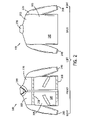
- FIG. 6 is a back view 14 of an alternate embodiment of the jacket 10 having a shoulder attachment region 45 , a mid-back attachment region 46 , and a waist-line attachment region 47 .
- the jacket 10 includes top section 16 , bottom section 18 , and collar 20 .
- the jacket 10 includes flaps 48 located at shoulder attachment region 45 that provide a flame-resistant protective layer to cover fastening mechanisms 49 A, 49 B, and 49 C.
- the jacket 10 similarly includes a flap 50 and fastening mechanisms 52 A, 52 B, 52 C, 52 D, 52 E, 52 F located at mid-back attachment region 46 .
- the jacket may include flap 54 as well as fastening mechanism 56 A, 56 B, 56 C, 56 D, 56 E, and 56 F located at waist-line attachment region 47 .
- flaps 48 , 50 , and 54 may include a flame-resistant layer to cover and protect the fastening mechanisms.
- FIG. 6 further illustrates male snaps as the fastening mechanism.
- fastening mechanisms 49 , 52 , and 56 may include a hook-and-loop system, a button system, a zipper system, a buckle system, a clip system, or a combination thereof.
- FIG. 7 illustrates bib 42 partially attached to the right side of jacket 10 at shoulder attachment region 45 .
- the figure shows flap 48 lifted to expose the fastening mechanism thereby enabling bib 42 to be removably attached to the jacket 10 .
- Female snaps 44 A, 44 B, and 44 C are separated or spaced apart so that they mate with male snaps 49 A, 49 B, and 49 C located on the right side of the jacket.
- female snaps 44 D, 44 E, and 44 F are separated or spaced apart so that they mate with male snaps 49 A, 49 B, 49 C, located on the left side of the jacket.
- Bib accessory 42 may be sized to substantially or entirely cover the shoulder region and upper torso of the wearer. This may be especially beneficial in over head welding applications.
- male snaps 52 A- 52 F and 56 A- 56 F may be spaced similar to female snaps 44 A- 44 F, such that bib 42 may be attached at either of these locations of jacket 10 .
- multiple fastening mechanisms enable the attachment of multiple welding accessories providing the wearer with the flexibility of multi-layering the flame-resistant garment.
- a first protective layer may be coupled to the jacket 10 at the region 45
- a second protective layer may be coupled to the jacket 10 at the region 46
- a third protective layer may be coupled to the jacket 10 at the region 47
- These protective layers on the back of the jacket 10 also may be in addition to one or more protective layers coupled to the front of the jacket 10 at areas 28 and 30 , as discussed in detail above.
- FIG. 8 illustrates an alternate bib 58 partially attached to the jacket 10 of FIG. 6 at the mid-back attachment region 46 .
- the figure illustrates bib 58 wrapping around the entire lower portion of the jacket 10 .
- alternate bib 58 includes attachment mechanisms 60 A, 60 B, 60 C, 60 D, 60 E, and 60 F arranged in a similar configuration to that of bib 42 .
- Bib 58 is attached to the mid-back attachment region 46 of the jacket 10 via male snaps 52 A, 52 B, 52 C, 52 D, 52 E, and 52 F.
- bib 58 is partially attached to the right side of the jacket with female snaps 60 A, 60 B, and 60 C coupled to male snaps 52 A, 52 B, and 52 C.
- the figure further illustrates bib 58 extending from the back right side of the jacket around to the front side of the jacket, and further around to the back left side of the jacket were the bib may be attached thereto.
- the bib provides 360 degree protection to a user as illustrated by the figure.
- FIG. 9A illustrate a front view of an alternate embodiment of a jacket system 62 that includes a sleeveless vest 64 and a sleeved bib or smock 66 .
- Sleeveless vest 64 includes a top section 68 , bottom section 70 , collar 72 , and sleeveless shoulder area 74 .
- Top section 68 includes collar 72 and shoulder area 74 , and terminates at a first bottom edge or upper attachment area 76 .
- Bottom section 70 extends from first bottom edge 76 and terminates at a second bottom edge or lower attachment area 78 .
- Bottom section 70 may be sized to substantially or entirely cover the lower torso of the wearer.
- top flap 80 and a bottom flap 82 are located at first bottom edge 76 and second bottom edge 78 , respectively.
- Top flap 80 and bottom flap 82 are made from a flame-resistant layer that covers and protects a top fastening mechanism 84 A, 84 B, and 84 C and a bottom fastening mechanism 86 A, 86 B, and 86 C. These mechanisms are located on both the left and right side of the jacket 10 . Additionally, the figure illustrates male snaps for the fastening mechanism, but as discussed above, the fastening mechanism is not limited to a snap fastener system.
- FIG. 9A also illustrates front view 88 of the sleeved bib or smock 66 .
- a smock may be defined as loose outer garment that protects a layer of clothes or other garment.
- Sleeved bib or smock 66 includes collar 90 , shoulder area 92 , right sleeve 94 , and left sleeve 84 .
- Sleeved bib 66 extends from the collar 90 to a bottom edge 98 .
- Attachment mechanisms 100 A, 100 B, 100 C, 100 D, 100 E, and 100 F are located near the bottom portion 98 of sleeved bib 66 .
- Both sleeved bib 66 and vest 64 may be made from any of the flame-resistant materials discussed above or any other suitable material.
- FIG. 9B illustrates the welding jacket system of 9 A with the sleeved bib 66 attached to the sleeveless vest 64 .
- the sleeved bib 66 is attached via the attachment mechanisms 100 A- 100 F coupled to the fastening mechanisms 84 A, 84 B, and 84 C located on both the left and right side of sleeveless vest 64 . Additional fastening and attachment mechanisms may also be included to further removably attach bib 66 to vest 64 .
- sleeveless vest 64 or sleeved bib 66 can be made from similar materials or they may be made from different materials.
- the vest 64 may be made of a first flame resistant material, and the vest 66 may be made of a second flame resistant material.
- the first and second flame resistant materials may be the same or different from one another.
- one or more protective layers, made of the same or different materials, may be coupled to the vest 64 via the attachment mechanisms 84 and/or 88 with or without the bib 66 .
- sleeveless vest 64 can be made from a lightweight flame-resistant material, whereas sleeved bib 66 can be made from a heavier more abrasion resistant material.
- This embodiment may be particularly useful for overhead welding procedures, which can result in molten metal, sparks, and BB's dropping onto the shoulder area 92 of the wearer. Further, this embodiment may be particularly useful in warmer climates enabling the user to remove the sleeved bib 66 and use the vest 64 alone or in combination with other protective layers.
- jacket system 62 enables the owner to replace sleeved bib 66 or the vest 64 without requiring the replacement of the entire jacket system 62 . This may be beneficial in situations where sleeved bib 66 takes the brunt of normal everyday wear and tear.
- sleeveless vest 64 may be made from various flame resistant fabrics and may even be in the form of a light weight flame-resistant shirt.
- FIG. 10 illustrates a front view of an alternate embodiment of a flame-resistant article of clothing in the form of pants or trousers 102 .
- Pants 102 include a waist section 104 , mid-thigh section 106 , shin section 108 , right leg 110 , and left leg 112 .
- Waist section 104 extends from a top edge 114 to a first edge 116 .
- Mid-thigh section 106 extends from the first edge 116 to a second edge 117 .
- shin section 108 extends from second edge 117 to the end of the pants 102 .
- pants 102 may include a number of flame-resistant layers or flaps. Flap 118 is located on top edge 114 and provides a flame-resistant protective layer to cover male snaps 120 A, 120 B, and 120 C. Similarly, flap 122 is located at first edge 116 and provides a flame-resistant protective layer to cover male snaps 124 A, 124 B, and 124 C. Further, flap 126 is located at second edge 117 and provides a flame-resistant protective layer to cover male snaps 128 A, 128 B, and 128 C. In one of the contemplated embodiments, waist section 104 , mid-thigh section 106 , and shin section 108 may be made from similar or different materials. These may include any of the flame-resistant discussed above or any other suitable material.
- FIG. 11 illustrates bib 42 partially attached to the right side of pants 102 to cover waist region 104 and a portion of mid-thigh region 106 .
- flap 118 may be lifted to expose fastening mechanisms 120 A, 120 B, and 120 C.
- Attachment mechanism 44 A, 44 B, and 44 C may then be coupled to fastening mechanisms 120 A, 120 B, and 120 C.
- bib 42 provides an additional flame-resistant layer for waist section 104 and mid-thigh section 106 . This configuration may be particularly useful for a welding application where the user is in a sitting position, such as at a bench, and the user would like to obtain additional protection to these sections.
- bib 42 may also be attached at first edge 116 or second edge 117 to provide a flame-resistant layer to the entire mid-thigh section 106 and/or shin region 108 .
- bib 42 attaches to the respective snaps 124 A- 124 C and/or 128 A- 128 C located on both the right and left side of pants 102 .
- a second bib or two independent bibs may be used in conjunction with first bib 42 to provide protection for each individual leg.
- additional fastening mechanisms may be located on the back side of the pants 102 to enable the wearer to wrap and secure bib 42 around a single leg. This configuration may be particularly useful for a welding application where the user is welding in a bent over position, such as for welding installed piping, and the user would like to provide additional protection to these sections.
- FIG. 12 illustrates a front view 132 of an alternate embodiment of a flame-resistant article of clothing in the form of a jumpsuit, coverall, or overalls 130 .
- Coverall 130 includes a top section 134 , bottom section 136 , a leg section 138 , a collar 140 , shoulder area 142 , left sleeve 144 , and right sleeve 146 .
- Top section 134 includes collar 140 and shoulder area 142 and terminates at a first edge 148 .
- Bottom section 136 extends from first edge 148 to second edge 150 .
- Leg section 138 extends from second edge 150 downward to include a right leg 152 and a left leg 154 that terminate at a third edge 156 .
- overall 130 may include a number of flame-resistant layers or flaps.
- Flap 158 is located at first edge 148 and provides a flame-resistant protective layer to cover male snaps 160 A, 160 B, and 160 C.
- flap 162 is located at second edge 150 and provides a flame-resistant protective layer to cover male snaps 164 A, 164 B, and 164 C.
- top section 134 , bottom section 136 , and leg section 138 may be made from similar or different materials. These materials may include any of the flame-resistant materials discussed above or any other suitable material.
- FIG. 12 further illustrates bib 42 removably attached to coveralls 130 at second edge 150 .
- flap 162 may be lifted to expose fastening mechanisms 164 A, 164 B, and 164 C, thereby enabling attachment mechanisms 44 A- 44 F to be coupled thereto.
- bib 42 provides an additional flame-resistant layer to cover the waist region and leg section 138 .
- bib 42 may also be attached to first edge 148 to provide a flame-resistant layer to cover bottom section 136 and leg section 138 .
- coveralls 130 may include additional fastening mechanisms that enable a wearer to provide added flame-resistant protection to other areas of the garment.
- coverall 130 could include additional fastening mechanisms similar to those illustrated in FIGS. 6 and 10 , for instance, on top of the shoulder area or at different locations along right leg 152 or left leg 154 .
- the fastening mechanism is not limited to a snap fastener system.
Landscapes
- Health & Medical Sciences (AREA)
- General Health & Medical Sciences (AREA)
- Physical Education & Sports Medicine (AREA)
- Engineering & Computer Science (AREA)
- Textile Engineering (AREA)
- Toxicology (AREA)
- Business, Economics & Management (AREA)
- Emergency Management (AREA)
- Professional, Industrial, Or Sporting Protective Garments (AREA)
Abstract
Description
- This application claims priority to U.S. Provisional Patent Application No. 60/854,905, entitled “ACCESSORY ATTACHMENTS FOR A WELDING JACKET”, filed on Oct. 27, 2006.
- The invention relates generally to a welding garment. More specifically, the invention relates to a flame-resistant welding garment, such as a welding jacket or another article of clothing, configured to receive a supplemental flame-resistant protective layer or other accessory attachments.
- Welding garments are typically a one-piece garment, which can be bulky and likely to retain body heat. If the welding garment is not worn by an operator, then the heat, sparks, or molten metal associated with a welding procedure may injure the operator due to a lack of flame resistance of normal clothing. However, in many facilities and applications, the operator may perform welding procedures intermittently rather than continuously throughout the day. Thus, the welding garment is not continuously needed for protection. Welding procedures often occur in uncontrollable, unpredictable, or extreme weather conditions, for example, high temperature and high humidity. These weather conditions can make the existing welding garments uncomfortable or unbearable to wear. As a result, the operator may be inclined to perform the welding procedures without the proper welding garment. In addition, if the welding garment becomes overly worn, damaged, or ineffective to protect against the welding conditions, then the entire welding garment is typically replaced at a significant cost.
- A flame resistant garment, in certain embodiments, may include multiple garment portions to provide different degrees of protection for welding or another application. In one embodiment, the flame-resistant garment may include a base garment and one or more supplemental protective layers or garments. For example, the base garment may include a jacket, a vest, a coverall, a jumpsuit, an overall, pants, trousers, a smock, a hat, a hood, or a combination thereof. The protective layer may include a bib or any other suitable attachment to add further flame resistance. Further, the multiple garment portions may be coupled together via a snap fastener system, a hook-and-loop system, a button system, a zipper system, a buckle system, or a clip system, or a combination thereof.
- These and other features, aspects, and advantages of the present invention will become better understood when the following detailed description is read with reference to the accompanying drawings in which like characters represent like parts throughout the drawings, wherein:
-
FIG. 1 illustrates a front elevational view and a back elevational view of an embodiment of a flame-resistant article of clothing, wherein the clothing includes a jacket having upper and lower portions made from first and second materials, respectively; -
FIG. 2 illustrates a front elevational view and a back elevational view of an alternate embodiment of the jacket shown inFIG. 1 ; -
FIG. 3 is a front elevational view of an embodiment of the jacket shown inFIGS. 1 and 2 , further illustrating a fastening mechanism located at an upper attachment area and a lower attachment area; -
FIG. 4 is a back elevational view of an embodiment of a flame-resistant protective layer of clothing, such as a bib, configured to couple with the jacket shown inFIGS. 1-3 ; -
FIG. 5A illustrates the bib ofFIG. 4 removably attached to the jacket ofFIGS. 1-3 at the upper attachment area; -
FIG. 5B illustrates the bib ofFIG. 4 removably attached to the jacket ofFIGS. 1-3 at the lower attachment area; -
FIG. 6 is a back elevational view of an alternate embodiment of the jacket ofFIG. 1 , wherein the jacket includes a shoulder attachment region, a mid-back attachment region, and a lower waist-line attachment region; -
FIG. 7 illustrates the bib ofFIG. 4 removably attached to the jacket ofFIG. 6 at the shoulder attachment region; -
FIG. 8 illustrates an alternate embodiment of a bib removably attached to the jacket ofFIG. 6 at the mid-back attachment region, wherein the bib wraps around the entire lower portion of the jacket; -
FIG. 9A is an alternate embodiment of a jacket system illustrating a smock and a vest configuration; -
FIG. 9B shows the jacket system ofFIG. 9A , illustrating the smock attached to the vest; -
FIG. 10 illustrates a front elevational view of an alternate embodiment of a flame-resistant article of clothing, wherein the clothing includes pants having a waist attachment section, a mid-thigh section, and a shin section; -
FIG. 11 illustrates the bib ofFIG. 4 removably attached to the pants ofFIG. 10 at the waist attachment section; and -
FIG. 12 illustrates a front elevational view of an alternate embodiment of a flame-resistant article of clothing, wherein the clothing includes a jumpsuit or overalls. - Various embodiments of a welding garment are disclosed that provide flame-resistant protection to a wearer. The garment may include a flame-resistant article of clothing that is configured to receive a protective layer of clothing via a fastening mechanism. The article of clothing may include a jacket, a vest, a coverall, a jumpsuit, an overall, pants, trousers, smock, a hat, a hood, or a combination thereof. The protective layer of clothing may include a bib or other accessory attachments. The accessory attachments provide for modularity or layering of flame-resistant material, thereby enabling the wearer to increase or decrease flame-resistant layers as desired. This is beneficial because it enables the operator to customize flame-resistant protection from one application to the next.
- For example, in one of the contemplated embodiments, the article of clothing is a welding jacket that includes a top section and a bottom section that may be made from the same or different flame-resistant materials. In a first operation, the wearer might be engaged in an over-head welding operation, thereby exposing his or her upper body to the heat intensive operation. Therefore, the wearer may desire more protection for the shoulder area during this operation as compared to a lower level welding operation, e.g., at a bench or in a bent over position.
- Additionally, the multi-layered system enables the user to wear the article of clothing in a fitted manner which may be more comfortable than a standard protective garment that only provides “one size fits all” protection. Finally, embodiments of the present invention reduce the cost of flame-resistant protection by enabling the user to replace worn or abraded accessory attachments without having to replace the entire article of clothing. This may also reduce the initial cost of the article of clothing by enabling the substitution of a less expensive material given it may only need to serve as a redundant layer to the attached accessory. Therefore, the article of clothing may not only be less expensive but may also be made from a lighter weight material to provide additional comfort for the wearer when he/she is not engaged in a welding operation.
- Turning now to the drawings,
FIG. 1 illustrates afront view 12A and aback view 14A of a flame-resistant article of clothing in the form ofjacket 10A.Welding jacket 10A may be made from any number of materials, including leather, in whole or in part. Additionally, welding jacket may be made from flame-resistant materials that may include a chemically treated natural fabric, a chemically treated natural fabric and synthetic fiber blend, a flame-resistant synthetic fiber blend, a flame-resistant leather, or a combination thereof. -
Welding jacket 10A includes a top section orupper portion 16A and a bottom section orlower portion 18A.Top section 16A includes acollar 20A,shoulder area 22A, a left sleeve 24, and a right sleeve 26. Thetop section 16A terminates at a first bottom edge orupper attachment area 28A.Bottom section 18A substantially covers the torso of the wearer and terminates in a second bottom edge orlower attachment area 30A.Lower attachment area 30A may be located at or below the waist of the person wearing the jacket, when the jacket is worn. In the illustrated embodiment shown inFIG. 1 ,top section 16A may be made of leather andbottom section 18A may be made of a flame-resistant cotton fabric or any other suitable material.Jacket 10A may be worn by the wearer in a standard fashion, and has a vertical zipper or vertical array of buttons that crosses thetop section 16A andbottom section 18A to enable opening or closing ofjacket 10A about the wearer. Additionally,collar 20A may include a number of different configurations, such as a barracuda style or square edged turned down style. -
FIG. 2 illustrates afront view 12B and aback view 14B of an alternate embodiment of awelding jacket 10B. Weldingjacket 10B includes atop section 16B, abottom section 18B, acollar 20B, ashoulder area 22B, aleft sleeve 24B, aright sleeve 26B, a firstbottom edge 28B, and a secondbottom edge 30B. Additionally,jacket 10B may include a hat or hood attached at or nearcollar 20B. In the embodiment ofFIG. 2 ,top section 16B andbottom section 18B are made from a single flame-resistant material, such as a flame-resistant cotton fabric, that is suitable forjacket 10B. Alternatively, as discussed with the embodiment illustrated inFIG. 1 ,top section 16B andbottom section 18B may include more than one flame-resistant material. - Specifically, the
top section 16B, thebottom section 18B, or both, may be made of a flame-resistant material including a cotton fabric impregnated with a flame retardant chemical; a vinal and polynosic rayon blend; an aramid synthetic fiber; a meta-aramid and para-aramid fiber blend; a meta-aramid, para-aramid, and modacrylic fiber blend; an oxidized polyacrylonitrile and aramid fiber blend; or a combination thereof. An exemplary embodiment of a cotton fabric impregnated with a flame retardant chemical is available from Westex Inc. in Chicago, Ill., and may be identified under the trademark INDURA. An exemplary embodiment of a cotton and high tenacity nylon fabric blend impregnated with a flame retardant chemical is also available from Westex Inc. and may be identified under the trademark INDURA Ultra Soft. Finally, Westex also provides an exemplary embodiment of a vinal and polynosic rayon blend that may be identified under the trademark Vinex. - Additionally, an exemplary embodiment of an aramid synthetic fiber is available from DuPont in Richmond, Va., and may be identified under the trademark NOMEX. An exemplary embodiment of a meta-aramid and para-aramid fiber blend is also available from DuPont and may be identified under the trademark NOMEX IIIA. DuPont also provides an exemplary embodiment of a meta-aramid, para-aramid, and modacrylic fiber blend that may be identified under the trademark Protera. Finally, an exemplary embodiment of an oxidized polyacrylonitrile and aramid fiber blend is available from Chapman Thermal Products in Salt Lake City, Utah, and may be identified under the trademark CarbonX. It should be noted that even though specific example of different materials have been disclosed, embodiments of the present invention are by no means limited to these materials and may include any suitable flame-resistant material. For example, the flame-resistant material may include leather, such as pigskin or goatskin leather.
- In the following figures, the alphabetic characters “A” and “B” of similar items illustrated and described with reference to
FIGS. 1 and 2 are shown in the figures, yet the following discussion excludes these characters for simplicity. Thus, only the numeric portion of each item is referenced in the following discussion.FIG. 3 illustrates another front view 12 of the jacket 10 shown inFIGS. 1 and 2 , further illustrating a fastening mechanism located at an upper attachment area and a lower attachment area. As with the previous figures,FIG. 3 illustrates jacket 10 having top section 16 and bottom section 18. Flame-resistant layers or flaps 32 and 38 are located at first bottom edge 28 and second bottom edge 30, respectively.Flaps - Specifically, one of the contemplated embodiments of the flame-resistant garment includes
male snaps -
FIG. 4 is a back view of an embodiment of a flame-resistant protective layer of clothing orprotective garment 42 in the form of a bib.Bib 42 is an accessory attachment having an attachment mechanism located along a top periphery of the bib. In one of the contemplated embodiments, the attachment mechanism includesfemale snaps male snaps female snaps male snaps Bib accessory 42 may be sized to substantially or entirely cover jacket 10 about the torso of the wearer when attached to the jacket at this location. Finally,male snaps male snaps bib 42 can be attached at this location of jacket 10. -
FIG. 5A illustratesbib 42 partially attached to the right side of jacket 10 at upper attachment area 28. The figure showsflaps 32 lifted to expose the fastening mechanism thereby enablingbib 42 to be removably attached to jacket 10. Similarly,FIG. 5B illustratesbib 42 partially attached to the right side of jacket 10 at the lower attachment area 30. As illustrated inFIG. 5B ,male snaps female snaps accessory attachment 42 may be sized to substantially or entirely cover the waste area and a portion of the legs down to the shin of the wearer. Finally, jacket 10 enables the wearer to use more than one protective garment or bib by including both upper attachment area 28 and lower attachment area 30 that enables simultaneous attachment of twoseparate welding accessories 42. Alternatively, thebib 42 may attach to both the upper and lower attachment areas 28, 30. Furthermore, thebib 42 may extend entirely or partially along the pants of a wearer, around the body of the wearer, or over the shoulders to cover the front and back of a wearer, or a combination thereof. -
FIG. 6 is a back view 14 of an alternate embodiment of the jacket 10 having ashoulder attachment region 45, amid-back attachment region 46, and a waist-line attachment region 47. In this embodiment, the jacket 10 includes top section 16, bottom section 18, and collar 20. Further, the jacket 10 includesflaps 48 located atshoulder attachment region 45 that provide a flame-resistant protective layer to coverfastening mechanisms flap 50 andfastening mechanisms mid-back attachment region 46. Additionally, the jacket may includeflap 54 as well asfastening mechanism line attachment region 47. As with the previous embodiments, flaps 48, 50, and 54 may include a flame-resistant layer to cover and protect the fastening mechanisms.FIG. 6 further illustrates male snaps as the fastening mechanism. However, embodiments of the present invention are by no means limited to a snap fastener system. As with the embodiments discussed above, fastening mechanisms 49, 52, and 56 may include a hook-and-loop system, a button system, a zipper system, a buckle system, a clip system, or a combination thereof. -
FIG. 7 illustratesbib 42 partially attached to the right side of jacket 10 atshoulder attachment region 45. The figure showsflap 48 lifted to expose the fastening mechanism thereby enablingbib 42 to be removably attached to the jacket 10. Female snaps 44A, 44B, and 44C are separated or spaced apart so that they mate withmale snaps female snaps male snaps Bib accessory 42 may be sized to substantially or entirely cover the shoulder region and upper torso of the wearer. This may be especially beneficial in over head welding applications. Additionally,male snaps 52A-52F and 56A-56F may be spaced similar tofemale snaps 44A-44F, such thatbib 42 may be attached at either of these locations of jacket 10. Again, multiple fastening mechanisms enable the attachment of multiple welding accessories providing the wearer with the flexibility of multi-layering the flame-resistant garment. In some embodiments, a first protective layer may be coupled to the jacket 10 at theregion 45, a second protective layer may be coupled to the jacket 10 at theregion 46, and a third protective layer may be coupled to the jacket 10 at theregion 47, These protective layers on the back of the jacket 10 also may be in addition to one or more protective layers coupled to the front of the jacket 10 at areas 28 and 30, as discussed in detail above. -
FIG. 8 illustrates analternate bib 58 partially attached to the jacket 10 ofFIG. 6 at themid-back attachment region 46. The figure illustratesbib 58 wrapping around the entire lower portion of the jacket 10. In this embodiment,alternate bib 58 includesattachment mechanisms bib 42.Bib 58 is attached to themid-back attachment region 46 of the jacket 10 via male snaps 52A, 52B, 52C, 52D, 52E, and 52F. In the figure,bib 58 is partially attached to the right side of the jacket withfemale snaps male snaps bib 58 extending from the back right side of the jacket around to the front side of the jacket, and further around to the back left side of the jacket were the bib may be attached thereto. In this embodiment, the bib provides 360 degree protection to a user as illustrated by the figure. -
FIG. 9A illustrate a front view of an alternate embodiment of ajacket system 62 that includes asleeveless vest 64 and a sleeved bib orsmock 66.Sleeveless vest 64 includes atop section 68,bottom section 70,collar 72, andsleeveless shoulder area 74.Top section 68 includescollar 72 andshoulder area 74, and terminates at a first bottom edge orupper attachment area 76.Bottom section 70 extends from firstbottom edge 76 and terminates at a second bottom edge orlower attachment area 78.Bottom section 70 may be sized to substantially or entirely cover the lower torso of the wearer. - Similarly to the previous embodiments, a
top flap 80 and abottom flap 82 are located at firstbottom edge 76 and secondbottom edge 78, respectively.Top flap 80 andbottom flap 82 are made from a flame-resistant layer that covers and protects atop fastening mechanism bottom fastening mechanism -
FIG. 9A also illustratesfront view 88 of the sleeved bib orsmock 66. A smock may be defined as loose outer garment that protects a layer of clothes or other garment. Sleeved bib orsmock 66 includescollar 90,shoulder area 92,right sleeve 94, and left sleeve 84.Sleeved bib 66 extends from thecollar 90 to abottom edge 98.Attachment mechanisms bottom portion 98 ofsleeved bib 66. Bothsleeved bib 66 andvest 64 may be made from any of the flame-resistant materials discussed above or any other suitable material. -
FIG. 9B illustrates the welding jacket system of 9A with thesleeved bib 66 attached to thesleeveless vest 64. Thesleeved bib 66 is attached via theattachment mechanisms 100A-100F coupled to thefastening mechanisms sleeveless vest 64. Additional fastening and attachment mechanisms may also be included to further removably attachbib 66 to vest 64. In this embodiment,sleeveless vest 64 orsleeved bib 66 can be made from similar materials or they may be made from different materials. For example, thevest 64 may be made of a first flame resistant material, and thevest 66 may be made of a second flame resistant material. The first and second flame resistant materials may be the same or different from one another. In addition, one or more protective layers, made of the same or different materials, may be coupled to thevest 64 via the attachment mechanisms 84 and/or 88 with or without thebib 66. - In some embodiments,
sleeveless vest 64 can be made from a lightweight flame-resistant material, whereassleeved bib 66 can be made from a heavier more abrasion resistant material. This embodiment may be particularly useful for overhead welding procedures, which can result in molten metal, sparks, and BB's dropping onto theshoulder area 92 of the wearer. Further, this embodiment may be particularly useful in warmer climates enabling the user to remove thesleeved bib 66 and use thevest 64 alone or in combination with other protective layers. Additionally,jacket system 62 enables the owner to replacesleeved bib 66 or thevest 64 without requiring the replacement of theentire jacket system 62. This may be beneficial in situations wheresleeved bib 66 takes the brunt of normal everyday wear and tear. Finally,sleeveless vest 64 may be made from various flame resistant fabrics and may even be in the form of a light weight flame-resistant shirt. -
FIG. 10 illustrates a front view of an alternate embodiment of a flame-resistant article of clothing in the form of pants ortrousers 102.Pants 102 include awaist section 104,mid-thigh section 106,shin section 108,right leg 110, andleft leg 112.Waist section 104 extends from atop edge 114 to afirst edge 116.Mid-thigh section 106 extends from thefirst edge 116 to asecond edge 117. Likewise,shin section 108 extends fromsecond edge 117 to the end of thepants 102. - As with the other flame resistant articles of clothing, pants 102 may include a number of flame-resistant layers or flaps.
Flap 118 is located ontop edge 114 and provides a flame-resistant protective layer to cover male snaps 120A, 120B, and 120C. Similarly,flap 122 is located atfirst edge 116 and provides a flame-resistant protective layer to cover male snaps 124A, 124B, and 124C. Further,flap 126 is located atsecond edge 117 and provides a flame-resistant protective layer to cover male snaps 128A, 128B, and 128C. In one of the contemplated embodiments,waist section 104,mid-thigh section 106, andshin section 108 may be made from similar or different materials. These may include any of the flame-resistant discussed above or any other suitable material. -
FIG. 11 illustratesbib 42 partially attached to the right side ofpants 102 to coverwaist region 104 and a portion ofmid-thigh region 106. As illustrated,flap 118 may be lifted to exposefastening mechanisms Attachment mechanism fastening mechanisms particular configuration bib 42 provides an additional flame-resistant layer forwaist section 104 andmid-thigh section 106. This configuration may be particularly useful for a welding application where the user is in a sitting position, such as at a bench, and the user would like to obtain additional protection to these sections. - Further,
bib 42 may also be attached atfirst edge 116 orsecond edge 117 to provide a flame-resistant layer to the entiremid-thigh section 106 and/orshin region 108. In these configurations,bib 42 attaches to therespective snaps 124A-124C and/or 128A-128C located on both the right and left side ofpants 102. Additionally, a second bib or two independent bibs may be used in conjunction withfirst bib 42 to provide protection for each individual leg. For example, additional fastening mechanisms may be located on the back side of thepants 102 to enable the wearer to wrap andsecure bib 42 around a single leg. This configuration may be particularly useful for a welding application where the user is welding in a bent over position, such as for welding installed piping, and the user would like to provide additional protection to these sections. -
FIG. 12 illustrates afront view 132 of an alternate embodiment of a flame-resistant article of clothing in the form of a jumpsuit, coverall, oroveralls 130.Coverall 130 includes atop section 134,bottom section 136, aleg section 138, acollar 140,shoulder area 142,left sleeve 144, andright sleeve 146.Top section 134 includescollar 140 andshoulder area 142 and terminates at a first edge 148.Bottom section 136 extends from first edge 148 tosecond edge 150.Leg section 138 extends fromsecond edge 150 downward to include aright leg 152 and aleft leg 154 that terminate at athird edge 156. - As with the other flame resistant articles of clothing, overall 130 may include a number of flame-resistant layers or flaps.
Flap 158 is located at first edge 148 and provides a flame-resistant protective layer to cover male snaps 160A, 160B, and 160C. Similarly,flap 162 is located atsecond edge 150 and provides a flame-resistant protective layer to cover male snaps 164A, 164B, and 164C. In one of the contemplated embodiments,top section 134,bottom section 136, andleg section 138 may be made from similar or different materials. These materials may include any of the flame-resistant materials discussed above or any other suitable material. -
FIG. 12 further illustratesbib 42 removably attached tocoveralls 130 atsecond edge 150. As shown in the figure,flap 162 may be lifted to exposefastening mechanisms attachment mechanisms 44A-44F to be coupled thereto. In this particular configuration,bib 42 provides an additional flame-resistant layer to cover the waist region andleg section 138. Further,bib 42 may also be attached to first edge 148 to provide a flame-resistant layer to coverbottom section 136 andleg section 138. Finally,coveralls 130 may include additional fastening mechanisms that enable a wearer to provide added flame-resistant protection to other areas of the garment. For example,coverall 130 could include additional fastening mechanisms similar to those illustrated inFIGS. 6 and 10 , for instance, on top of the shoulder area or at different locations alongright leg 152 orleft leg 154. Additionally, although the figure illustrates male snaps, the fastening mechanism is not limited to a snap fastener system. - While only certain features of the invention have been illustrated and described herein, many modifications and changes will occur to those skilled in the art. It is, therefore, to be understood that the appended claims are intended to cover all such modifications and changes as fall within the true spirit of the invention.
Claims (28)
Priority Applications (1)
| Application Number | Priority Date | Filing Date | Title |
|---|---|---|---|
| US11/740,814 US9731152B2 (en) | 2006-10-27 | 2007-04-26 | Accessory attachments for a welding garment |
Applications Claiming Priority (2)
| Application Number | Priority Date | Filing Date | Title |
|---|---|---|---|
| US85490506P | 2006-10-27 | 2006-10-27 | |
| US11/740,814 US9731152B2 (en) | 2006-10-27 | 2007-04-26 | Accessory attachments for a welding garment |
Publications (2)
| Publication Number | Publication Date |
|---|---|
| US20080098503A1 true US20080098503A1 (en) | 2008-05-01 |
| US9731152B2 US9731152B2 (en) | 2017-08-15 |
Family
ID=39328379
Family Applications (1)
| Application Number | Title | Priority Date | Filing Date |
|---|---|---|---|
| US11/740,814 Active 2032-03-09 US9731152B2 (en) | 2006-10-27 | 2007-04-26 | Accessory attachments for a welding garment |
Country Status (1)
| Country | Link |
|---|---|
| US (1) | US9731152B2 (en) |
Cited By (18)
| Publication number | Priority date | Publication date | Assignee | Title |
|---|---|---|---|---|
| US20080289078A1 (en) * | 2007-05-08 | 2008-11-27 | Nike, Inc. | Articles of Apparel Including Zones Having Increased Thermally Insulative and Thermally Resistive Properties |
| US20090031486A1 (en) * | 2007-08-02 | 2009-02-05 | Nike, Inc. | Articles Of Base Layer Apparel Including Zones Having Different Thermal Properties |
| CN101947368A (en) * | 2010-06-02 | 2011-01-19 | 陈欣荣 | Flame-retardant body strengthening safety clothing of nano-element fiber fabric |
| US20110271419A1 (en) * | 2005-05-02 | 2011-11-10 | Vereen William C | Shirt with reinforced front |
| US20120079639A1 (en) * | 2010-10-01 | 2012-04-05 | Hughes Griffith W | Cut resistant garment |
| EP2409585A3 (en) * | 2010-07-21 | 2012-10-10 | Nigel Colin Fletcher | Chainsaw protective trousers or chaps |
| US20140261852A1 (en) * | 2013-03-13 | 2014-09-18 | Springfield Llc | Flame-Resistant Fiber Blend, Yarn, and Fabric, and Method for Making Same |
| USD721470S1 (en) * | 2013-03-21 | 2015-01-27 | Earle W. Kolb | Jacket with snakeskin-like pattern |
| CN105286120A (en) * | 2015-10-15 | 2016-02-03 | 佛山市维晨科技有限公司 | Nano protective material having synergistic function and preparation method of protective material |
| USD765351S1 (en) | 2013-05-28 | 2016-09-06 | Weldarmor Inc. | Sweater |
| US9462833B1 (en) | 2014-10-14 | 2016-10-11 | Bali Kini Co. | Interchangeable and adjustable bikini attachment and closure system |
| US20160295950A1 (en) * | 2015-04-09 | 2016-10-13 | Mackenzie D. SCHURR | Upper garment worn during overhead welding |
| USD833116S1 (en) * | 2015-05-26 | 2018-11-13 | Clothing Arts, Ltd. | Jacket |
| CN114010971A (en) * | 2021-10-29 | 2022-02-08 | 盐城华轩服装有限公司 | Rain-proof functional clothing that flame retardant effect is good |
| USD947498S1 (en) | 2018-09-06 | 2022-04-05 | Cowboys of the Sky Original Work Pants, LLC | Pair of pants |
| USD982283S1 (en) | 2021-06-08 | 2023-04-04 | Earle W. Kolb | Jacket with snakeskin-like pattern |
| US11761124B1 (en) | 2021-09-09 | 2023-09-19 | Milliken & Company | Elastic flame-resistant fabric |
| US12247329B2 (en) | 2019-09-04 | 2025-03-11 | Milliken & Company | Flame-resistant fabric |
Families Citing this family (2)
| Publication number | Priority date | Publication date | Assignee | Title |
|---|---|---|---|---|
| US12458079B2 (en) * | 2021-07-26 | 2025-11-04 | Birthings, Llc | Multifunctional labor support gown |
| USD1121269S1 (en) | 2022-07-26 | 2026-04-07 | Birthings Llc | Multifunctional labor support gown |
Citations (15)
| Publication number | Priority date | Publication date | Assignee | Title |
|---|---|---|---|---|
| US187405A (en) * | 1877-02-13 | Improvement in jackets | ||
| US380576A (en) * | 1888-04-03 | Vest-protector | ||
| US1068976A (en) * | 1912-01-03 | 1913-07-29 | William Buckler | Wearing-apparel. |
| US1165538A (en) * | 1914-02-19 | 1915-12-28 | Montgomery Washburn Company | Apron. |
| US1193545A (en) * | 1916-08-08 | James h | ||
| US2388234A (en) * | 1944-06-02 | 1945-11-06 | George H Abel | Welder's protective cape |
| US2389152A (en) * | 1942-04-15 | 1945-11-20 | American Optical Corp | Protection garment |
| US3691564A (en) * | 1970-11-04 | 1972-09-19 | American Optical Corp | Protective garment |
| US3961376A (en) * | 1975-03-06 | 1976-06-08 | Howell Evelyn M | Detachable connection for combination shorts and skirt |
| US4890336A (en) * | 1988-05-02 | 1990-01-02 | Barry Worton | Welding protected coveralls |
| US4999850A (en) * | 1989-12-26 | 1991-03-19 | Grilliot William L | Firefighter's integrated garment |
| US5727401A (en) * | 1995-08-09 | 1998-03-17 | Southern Mills, Inc. | Fire resistant fleece fabric and garment |
| US20060277651A1 (en) * | 2005-04-14 | 2006-12-14 | Ali Razzaghi | Protective garment with curved and protected extremities |
| US20070094763A1 (en) * | 2002-08-30 | 2007-05-03 | Safety-Short Workwair Inc. | Safety outerwear with fire resistant mesh |
| US20070245443A1 (en) * | 2006-04-11 | 2007-10-25 | Vereen William C | Breathable, vented, flame resistant shirt |
Family Cites Families (1)
| Publication number | Priority date | Publication date | Assignee | Title |
|---|---|---|---|---|
| GB2011244A (en) * | 1977-05-17 | 1979-07-11 | Leisurelite Ltd | Improvements in or relating to protective garments |
-
2007
- 2007-04-26 US US11/740,814 patent/US9731152B2/en active Active
Patent Citations (15)
| Publication number | Priority date | Publication date | Assignee | Title |
|---|---|---|---|---|
| US187405A (en) * | 1877-02-13 | Improvement in jackets | ||
| US380576A (en) * | 1888-04-03 | Vest-protector | ||
| US1193545A (en) * | 1916-08-08 | James h | ||
| US1068976A (en) * | 1912-01-03 | 1913-07-29 | William Buckler | Wearing-apparel. |
| US1165538A (en) * | 1914-02-19 | 1915-12-28 | Montgomery Washburn Company | Apron. |
| US2389152A (en) * | 1942-04-15 | 1945-11-20 | American Optical Corp | Protection garment |
| US2388234A (en) * | 1944-06-02 | 1945-11-06 | George H Abel | Welder's protective cape |
| US3691564A (en) * | 1970-11-04 | 1972-09-19 | American Optical Corp | Protective garment |
| US3961376A (en) * | 1975-03-06 | 1976-06-08 | Howell Evelyn M | Detachable connection for combination shorts and skirt |
| US4890336A (en) * | 1988-05-02 | 1990-01-02 | Barry Worton | Welding protected coveralls |
| US4999850A (en) * | 1989-12-26 | 1991-03-19 | Grilliot William L | Firefighter's integrated garment |
| US5727401A (en) * | 1995-08-09 | 1998-03-17 | Southern Mills, Inc. | Fire resistant fleece fabric and garment |
| US20070094763A1 (en) * | 2002-08-30 | 2007-05-03 | Safety-Short Workwair Inc. | Safety outerwear with fire resistant mesh |
| US20060277651A1 (en) * | 2005-04-14 | 2006-12-14 | Ali Razzaghi | Protective garment with curved and protected extremities |
| US20070245443A1 (en) * | 2006-04-11 | 2007-10-25 | Vereen William C | Breathable, vented, flame resistant shirt |
Cited By (27)
| Publication number | Priority date | Publication date | Assignee | Title |
|---|---|---|---|---|
| US20110271419A1 (en) * | 2005-05-02 | 2011-11-10 | Vereen William C | Shirt with reinforced front |
| US8856964B2 (en) * | 2007-05-08 | 2014-10-14 | Nike, Inc. | Articles of apparel including zones having increased thermally insulative and thermally resistive properties |
| US20080289078A1 (en) * | 2007-05-08 | 2008-11-27 | Nike, Inc. | Articles of Apparel Including Zones Having Increased Thermally Insulative and Thermally Resistive Properties |
| US10448681B2 (en) | 2007-05-08 | 2019-10-22 | Nike, Inc. | Articles of apparel including zones having increased thermally insulative and thermally resistive properties |
| US20090031486A1 (en) * | 2007-08-02 | 2009-02-05 | Nike, Inc. | Articles Of Base Layer Apparel Including Zones Having Different Thermal Properties |
| CN101947368B (en) * | 2010-06-02 | 2013-11-13 | 陈欣荣 | Flame-retardant body strengthening safety clothing of nano-element fiber fabric |
| CN101947368A (en) * | 2010-06-02 | 2011-01-19 | 陈欣荣 | Flame-retardant body strengthening safety clothing of nano-element fiber fabric |
| EP2409585A3 (en) * | 2010-07-21 | 2012-10-10 | Nigel Colin Fletcher | Chainsaw protective trousers or chaps |
| US8978162B2 (en) * | 2010-10-01 | 2015-03-17 | Banom, Inc. | Cut resistant garment |
| US20120079639A1 (en) * | 2010-10-01 | 2012-04-05 | Hughes Griffith W | Cut resistant garment |
| US9920474B2 (en) * | 2013-03-13 | 2018-03-20 | Milliken & Company | Flame-resistant fiber blend, yarn, and fabric, and method for making same |
| US20140261852A1 (en) * | 2013-03-13 | 2014-09-18 | Springfield Llc | Flame-Resistant Fiber Blend, Yarn, and Fabric, and Method for Making Same |
| USD721470S1 (en) * | 2013-03-21 | 2015-01-27 | Earle W. Kolb | Jacket with snakeskin-like pattern |
| USD765351S1 (en) | 2013-05-28 | 2016-09-06 | Weldarmor Inc. | Sweater |
| US9462833B1 (en) | 2014-10-14 | 2016-10-11 | Bali Kini Co. | Interchangeable and adjustable bikini attachment and closure system |
| US11350690B2 (en) * | 2015-04-09 | 2022-06-07 | Up In Smoke Welding Apparel Inc. | Upper garment worn during overhead welding |
| US20160295950A1 (en) * | 2015-04-09 | 2016-10-13 | Mackenzie D. SCHURR | Upper garment worn during overhead welding |
| US11882894B2 (en) * | 2015-04-09 | 2024-01-30 | Up In Smoke Welding Apparel Inc. | Upper garment worn during overhead welding |
| US20220279889A1 (en) * | 2015-04-09 | 2022-09-08 | Up In Smoke Welding Apparel Inc. | Upper garment worn during overhead welding |
| USD833116S1 (en) * | 2015-05-26 | 2018-11-13 | Clothing Arts, Ltd. | Jacket |
| CN105286120A (en) * | 2015-10-15 | 2016-02-03 | 佛山市维晨科技有限公司 | Nano protective material having synergistic function and preparation method of protective material |
| USD947498S1 (en) | 2018-09-06 | 2022-04-05 | Cowboys of the Sky Original Work Pants, LLC | Pair of pants |
| US12247329B2 (en) | 2019-09-04 | 2025-03-11 | Milliken & Company | Flame-resistant fabric |
| US12320042B2 (en) | 2019-09-04 | 2025-06-03 | Milliken & Company | Flame-resistant fabric |
| USD982283S1 (en) | 2021-06-08 | 2023-04-04 | Earle W. Kolb | Jacket with snakeskin-like pattern |
| US11761124B1 (en) | 2021-09-09 | 2023-09-19 | Milliken & Company | Elastic flame-resistant fabric |
| CN114010971A (en) * | 2021-10-29 | 2022-02-08 | 盐城华轩服装有限公司 | Rain-proof functional clothing that flame retardant effect is good |
Also Published As
| Publication number | Publication date |
|---|---|
| US9731152B2 (en) | 2017-08-15 |
Similar Documents
| Publication | Publication Date | Title |
|---|---|---|
| US9731152B2 (en) | Accessory attachments for a welding garment | |
| US7181774B2 (en) | Ventilated safety outerwear | |
| CA2709386C (en) | Ventilated trousers | |
| US7832022B1 (en) | Pants apparatus and method of use | |
| US8898813B2 (en) | Easy access individual needs one piece garment | |
| US9247774B2 (en) | Easy access individual needs one piece garment | |
| US5095549A (en) | Firefighter pant support system | |
| US7451495B2 (en) | Combined garment and safety harness | |
| CN101917880B (en) | Coverall that be handy for activity | |
| EP1924163B1 (en) | Sport garment having an improved comfortableness | |
| US7913321B2 (en) | Child carrier cover | |
| US20230240394A1 (en) | Multi-use article with quick release closure | |
| AU2008318274B2 (en) | Protective clothing | |
| US12433353B2 (en) | Protective blazer for motorcyclists | |
| US20080256690A1 (en) | Rounded contour pocket | |
| US20200282243A1 (en) | Advanced Multi-Threat Base Ensemble for Emergency Responders | |
| JP2009511770A (en) | Cut-resistant and wear-resistant modular protective clothing and protective clothing system | |
| KR102455766B1 (en) | Work clothes integrated with industrial harness | |
| US20080060112A1 (en) | Motorcycle jacket | |
| US20160059050A1 (en) | Light-weight, flame-resistant coveralls with knitted, stretchable portion for upper torso | |
| US20230037727A1 (en) | Protective garment for use with heavy apparatus/protective vest, act as a filter and identity protector | |
| US12507744B2 (en) | Protective jacket for motorcyclists with a detachable blazer | |
| RU114144U1 (en) | PROTECTIVE OVERALLS FOR PROTECTION AGAINST SPLITS, CUTS AND EXPOSURE OF THE FIRE UNDER THE VEHICLE | |
| US20250280901A1 (en) | Undergarment for protecting outer garments from armpit perspiration | |
| AU2014100120A4 (en) | Protective Clothing |
Legal Events
| Date | Code | Title | Description |
|---|---|---|---|
| AS | Assignment |
Owner name: ILLINOIS TOOL WORKS INC., ILLINOIS Free format text: ASSIGNMENT OF ASSIGNORS INTEREST;ASSIGNOR:SWARTZ, JOHN A., IV;REEL/FRAME:019218/0736 Effective date: 20070425 |
|
| FEPP | Fee payment procedure |
Free format text: PAYOR NUMBER ASSIGNED (ORIGINAL EVENT CODE: ASPN); ENTITY STATUS OF PATENT OWNER: LARGE ENTITY |
|
| STCF | Information on status: patent grant |
Free format text: PATENTED CASE |
|
| MAFP | Maintenance fee payment |
Free format text: PAYMENT OF MAINTENANCE FEE, 4TH YEAR, LARGE ENTITY (ORIGINAL EVENT CODE: M1551); ENTITY STATUS OF PATENT OWNER: LARGE ENTITY Year of fee payment: 4 |
|
| MAFP | Maintenance fee payment |
Free format text: PAYMENT OF MAINTENANCE FEE, 8TH YEAR, LARGE ENTITY (ORIGINAL EVENT CODE: M1552); ENTITY STATUS OF PATENT OWNER: LARGE ENTITY Year of fee payment: 8 |