US20070136498A1 - KVM system for controlling computers and method thereof - Google Patents
KVM system for controlling computers and method thereof Download PDFInfo
- Publication number
- US20070136498A1 US20070136498A1 US11/302,943 US30294305A US2007136498A1 US 20070136498 A1 US20070136498 A1 US 20070136498A1 US 30294305 A US30294305 A US 30294305A US 2007136498 A1 US2007136498 A1 US 2007136498A1
- Authority
- US
- United States
- Prior art keywords
- menu
- video signal
- computers
- video
- data
- Prior art date
- Legal status (The legal status is an assumption and is not a legal conclusion. Google has not performed a legal analysis and makes no representation as to the accuracy of the status listed.)
- Granted
Links
Images


Classifications
-
- G—PHYSICS
- G06—COMPUTING OR CALCULATING; COUNTING
- G06F—ELECTRIC DIGITAL DATA PROCESSING
- G06F3/00—Input arrangements for transferring data to be processed into a form capable of being handled by the computer; Output arrangements for transferring data from processing unit to output unit, e.g. interface arrangements
- G06F3/01—Input arrangements or combined input and output arrangements for interaction between user and computer
- G06F3/02—Input arrangements using manually operated switches, e.g. using keyboards or dials
- G06F3/023—Arrangements for converting discrete items of information into a coded form, e.g. arrangements for interpreting keyboard generated codes as alphanumeric codes, operand codes or instruction codes
-
- G—PHYSICS
- G06—COMPUTING OR CALCULATING; COUNTING
- G06F—ELECTRIC DIGITAL DATA PROCESSING
- G06F3/00—Input arrangements for transferring data to be processed into a form capable of being handled by the computer; Output arrangements for transferring data from processing unit to output unit, e.g. interface arrangements
- G06F3/01—Input arrangements or combined input and output arrangements for interaction between user and computer
- G06F3/03—Arrangements for converting the position or the displacement of a member into a coded form
- G06F3/033—Pointing devices displaced or positioned by the user, e.g. mice, trackballs, pens or joysticks; Accessories therefor
- G06F3/038—Control and interface arrangements therefor, e.g. drivers or device-embedded control circuitry
Definitions
- the present invention generally relates to a KVM system for controlling computers and the method used for the same, and more particularly to a system and method capable of controlling computers by processing keyboard-video-mouse (KVM) signals.
- KVM keyboard-video-mouse
- KVM keyboard-video-mouse
- An on-screen display (OSD) menu interface concept is raised for convenience of operation on controlling the plurality of remote computers. The user can directly select any one of the plurality of computers from the OSD menu graphically presented on a displayer coupled to the console.
- OSD on-screen display
- the design of the KVM switch has greatly been improved on aspects of functions. Especially, the number of computers joined to the network can be greatly increased for complying with explosive growth of various network neighborhoods.
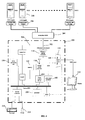
- an on-screen display (OSD) menu was constructed by video signals generated from an on-screen display (OSD) circuit 14 , e.g. an OSD Chip. Then the video signals of the on-screen display (OSD) menu are transmitted to an overlay circuit 12 .
- the overlay circuit 12 is able to simultaneously receive and combine the real-time video signals from a remote computer and the video signals of the OSD menu.
- an overlay signal generated by combining the real-time video signals from the selected computer with the video signals related to the OSD menu is outputted to the monitor.
- a traditional OSD menu image graphed over a managing image from the selected computer is displayed on the central position of the monitor 212 .
- the OSD circuit 12 is used for generating the video signal of the OSD menu.
- An overlay circuit 14 is used to combine the real-time video signal from the computer and the video signal of the OSD menu. Nevertheless, the signal processes for both the OSD circuit 14 and overlay circuit 12 are greatly complicated.
- the overlay circuit 12 according to a keyboard/mouse signal (OSD menu enable signal) through the KVM switch 18 to determine whether the video signal of the OSD menu or the video signal from the computer is outputted for every single pixel on the monitor.
- the signal processes of both the OSD and overlay circuit 12 , 14 need a large number
- An object of the present invention is to provide a KVM system for controlling computers and the method for the same, which is able to actively generate a menu or an image constructed by real-time video signals from at least one of the computers on a video monitor of a console.
- Another object of the present invention is to provide a KVM system for controlling computers and the method for the same, which is able to preview a preview image constructed by video signals from the computers by picking up the menu image.
- the present invention provides a KVM system for connecting a console device having a keyboard, cursor control device and video monitor to a number of computers.
- the KVM system comprises a user-side circuit, a central crosspoint switch, a plurality of computer-side circuits and a graphic user interface menu apparatus comprising at least a menu generating unit and a first switching device.
- the user-side circuit couples to the console device for receiving electronic signals produced by the keyboard and cursor control device and for creating a data packet that includes the electronic signals.
- the central crosspoint switch couples to the user-side circuits and includes a number of inputs and a number of outputs, the central crosspoint switch receives the data packets from one of the inputs and routes the data packets to one or more of the outputs.
- the plurality of computer-side circuits couple to the central crosspoint switch and the computers and receives the data packets transmitted from the central crosspoint switch for supplying the data packets to one of the computers.
- the menu generating unit of the graphic user interface menu apparatus generates a menu data.
- the first switching device outputs the menu data or a real-time video signal from one of the computers to the video monitor.
- the graphic user interface menu apparatus comprises an image capture device deposed between the console device and the computers to capture the video signals from the computers to construct the preview images.
- the graphic user interface menu apparatus further comprises a processor, a memory and a video signal generator.
- the processor controls all devices in the graphic user interface menu apparatus.
- the memory is used to pre-store the preview images temporarily.
- the video signal generator coupled to the first switch device, generates the menu data to the video monitor.
- a method for controlling a number of computers principally comprises the steps of:
- the present invention further comprises the following steps of:
- FIG. 1 illustrates a system with a traditional OSD menu on the video monitor according to the prior art
- FIG. 2 illustrates a frame with traditional OSD menu composed of texts on the video monitor, according to the system of FIG. 1 ;
- FIG. 3 illustrates a KVM system having a graphic user interface menu apparatus located in a central crosspoint switch of the KVM system connected between a console device including a keyboard, cursor control device and video monitor and a number of computers, according to a first embodiment of the present invention
- FIG. 4 illustrates a KVM system having a graphic user interface menu apparatus located in a user-side circuit of the KVM system connected between a console device and a number of computers, according to a second embodiment of the present invention
- FIG. 5 illustrates a KVM system having a graphic user interface menu apparatus located in a central crosspoint switch of the KVM system that the KVM signals transmitted between a console device and a number of computers according to a third embodiment of the present invention
- FIG. 6 illustrates a KVM system having a graphic user interface menu apparatus further comprising a synchronization signal source for the menu generating unit according to a fourth embodiment of the present invention
- FIG. 7 illustrates a result of alternately switching two frames constructed by the real-time image of the computer and the image of the OSD menu according to an embodiment of the present invention
- FIG. 8 illustrates a frame, which shows a graphic user interface menu initially activated after a keystroke command of the keyboard
- FIG. 9 illustrates a frame that shows a graphic user interface menu image arranged side by side with four preview images relative to four different computers
- FIG. 10 illustrates a frame that shows a graphic user interface menu image arranged side by side with a specific preview image from a single selected computer
- FIG. 11 illustrates a frame that a viewing screen relative to either the console device or the selected computer is being switched by a scrolling-down submenu in the graphic user interface menu.
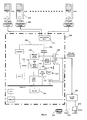
- FIG. 3 illustrates a KVM system according to a first embodiment of the present invention, principally including a user-side circuit 202 , a central crosspoint switch 204 and a plurality of computer-side circuits 206 .
- the central crosspoint switch 204 such as a KVM switch, having a number of inputs and a number of outputs, is connected to a console device including a keyboard 216 , a cursor control device 214 which can control the movement of the cursor, such as a mouse, a touch pad or a track ball, and a video monitor 212 through the user-side circuit 202 , and alternatively is connected to a plurality of computers 218 (i.e.
- the central crosspoint switch 204 receives the data packets (or a differential signal, or analog signal, depending on a communication specification adaptive of the KVM switch 204 ) from one of the inputs and routes the data packets to one or more of the outputs thereof.
- the plurality of computer-side circuits 206 receives the data packets transmitted from the central crosspoint switch 204 for supplying the data packets to at least one of the computers 218 .
- the KVM system employs a graphic user interface menu apparatus located in said central crosspoint switch 204 .
- the graphic user interface menu apparatus principally includes a menu generating unit 104 , a first switching device 110 , a image capture device 102 , a processor 106 , a video signal generator 108 , a memory 112 and a second switching device 114 .
- the menu generating unit 104 can be realized by an ASIC to generate the graphic user interface menu or even just a storing device that stores a special software program for generating the graphic user interface menu to be displayed on the video monitor 212 .
- the user-side circuit 202 coupled to the console device is used to receive electronic signals produced by the keyboard 216 and cursor control device 214 , and create a data packet that contains the electronic signals.
- Part of inputs of the central crosspoint switch 204 are used for receiving the data packets from one of the console devices, and part of outputs of the central crosspoint switch 204 are used for routing the data packets from the user-side circuit 202 to one or more of the outputs.
- the computer-side circuits 206 the computer 218 receives the data packets transmitted from the central crosspoint switch 204 .
- the menu generating unit 104 of the graphic user interface menu apparatus pre-stores menu data in the apparatus for generating a specific graphic user interface (GUI) menu image on the video monitor 212 .
- the image capture device 102 of the graphic user interface menu apparatus is operative to capture video signals from the computer 218 to construct image files convenient to the user's preview, which are respectively pre-stored in a memory 112 , temporarily.
- the processor 106 controls all units in the graphic user interface menu apparatus.
- the video signal generator 108 parses the menu data pre-stored in the menu generating unit 104 to generate the video signals that can construct a GUI menu image on the video monitor 212 .
- the first switch device 110 realized as a multiplexer, according to the user's command, selectably outputs the menu data or the real-time video signal from the selected computer to the video monitor of the console device, as switching different viewing screen outputs. That is, once the image of the menu data is presented on the video monitor of the console, the real-time video signal from the selected computer is blocked by the first switch device 110 . Therefore, the real-time video signal cannot be output to the video monitor of the console device. As a result, a menu without any background is presented on the video monitor of the console device.
- the graphic user interface menu apparatus further includes a second switching device 114 , which is located in central crosspoint switch 204 for selectably outputting the real-time video signals from the computer 218 or other computers to the first switching device 110 .
- the second switching device 114 can be a multiplexer or a demultiplexer.
- the communication line 302 is for transmitting video signals and the communication line 304 is for transmitting keyboard, cursor control device signals.
- the graphic user interface menu apparatus further includes an analog-to-digital converter 116 , a differential-to-analog converter 118 and an analog-to-differential converter 120 .
- the differential-to-analog converter 118 transforms the differential video signals into analog video signals.
- the analog-to-digital converter 116 transforms the video signals into video data, which is consumed by the image capture device 102 to construct the preview image.
- the analog-to-differential converter 120 coupled to the video signal generator 108 transforms the analog video signals into the differential video signals used for the first switching device 110 .
- transceiver UART
- GPIO GPIO
- FIG. 4 It illustrates a KVM system having a graphic user interface menu apparatus located in a user-side circuit, according to a second embodiment of the present invention.
- the graphic user interface apparatus merely receives the video signals from the central crosspoint switch 204 without need of selecting the computer 218 .
- the video signals i.e. RGB signals for the video monitor 212 shown in FIG. 4
- the video signal generator 108 are generated by the video signal generator 108 and are then transmitted through the first switching device 110 to the video monitor 212 of the console device for user's view.
- the transceiver, UART and GPIO additional keyboard, cursor control device controller (KB/MS controller) shown in figures are mostly related with processing keyboard, cursor control device signals.
- FIG. 5 It illustrates a KVM system having a graphic user interface menu apparatus located in a central crosspoint switch 204 , according to the third embodiment of the present invention.
- the KVM signal is transmitted through the system in the form of analog. Therefore, in this third embodiment with usage of analog keyboard, video, cursor control device data, an analog-to-digital converter is employed to transform the analog video signals into data packets for processor 106 and other related component.
- FIG. 6 It illustrates a system having a graphic user interface menu apparatus according to a fourth embodiment of the present invention, which includes a synchronization signal source for the menu generating unit 122 .
- the menu generating unit 104 mentioned in FIG. 3 can be implemented in a form of software.
- the menu generating unit 122 shown in FIG. 6 with a synchronization signal source 124 is implemented in a form of hardware.
- the present invention provides the synchronization signal source 124 for the menu generating unit 122 to generate an OSD menu.
- the IC production named “MTV021” manufactured by Myson Technology the OSD menu only shows up alone in the video monitor 212 of the console device as same as the previous three embodiments.
- the first switching device 110 outputs either the menu data or the real-time video signals from one of the computers to the video monitor.
- the menu generating unit 122 generates a graphic user interface menu like the first to third embodiment.
- FIG. 7 Please refer to FIG. 7 .
- the present invention still can display the real-time video signals of the computer for the user.
- FIG. 6 shows that a vertical synchronization signal (VSYNC) 124 - 1 is provided to the first switching device 110 to control the outputting of the first switching device 110 .
- the vertical synchronization signal 124 - 1 can come from the same source as synchronization signal 124 (VSYNC) or a different source from the synchronization signal 124 .
- the synchronization signal's 124 source is from the computer 218 or other computer.
- the purpose of the synchronization signal is to synchronize the video signals (red, green, blue colors) of the OSD menu when outputted to the monitor.
- the vertical synchronization signal 124 - 1 is employed as a toggle signal to control the outputting of the first switching device 110 .
- both the vertical synchronization signal 124 and 124 - 1 are from the same source of the computer.
- the added vertical synchronization signal 124 - 1 is employed to determine whether the real-time video signals from the computer or the video signals of the OSD menu will be outputted to the monitor. Therefore, the GUI apparatus can use vertical synchronization signal 124 - 1 to control the first switching unit 110 alternately outputting the menu data and the real-time video signals from the computer to the video monitor 212 .
- the first switching unit 110 outputs the video signals of the order: frame 1 -frame 2 -frame 3 -frame 4 alternately as shown in FIG. 7 .
- the odd frames, such as Frames 1 and 3 images are constructed by the video signals from the computer, the even frames, such as Frames 2 and 4 images, are constructed by the video signals from the OSD menu generating unit.
- the first switching device 110 outputs the Frame 1 . Thereafter, once the first switching device 110 receives the vertical synchronization signal 124 - 1 , the first switching device 110 alters to output the Frame 2 constructed by the video signals from the OSD menu generating unit. After that, once the first switching device 110 receives the vertical synchronization signal 124 - 1 again, the first switching device 110 alters to output the Frame 3 constructed by the video signals from the computer.
- the frequency of the vertical synchronization signal 124 - 1 can be 60 Hz, 75 Hz or even higher.
- the menu generating unit 122 When the user uses a keystroke or a sequence of keystrokes of the keyboard to activate a GUI menu, the menu generating unit 122 according to the keystroke generates a menu data. Then a graphic user interface menu constructed by the menu data is shown on the video monitor, as presented in FIG. 7 .
- the device management explorer area 502 a plurality of icons representing the devices are shown in a tree schema. The user can easily understand the real connection of all devices fully at a glance, even through a real connection in cascade, e.g. five levels, or even eight levels. Unlike the prior art, a text-only OSD menu revealing little information may easily confuse the user.
- a preview image from the selected computer will show up on user's demand. In the embodiment, the preview area 504 is blank when the graphic user interface menu is activated initially.
- FIG. 8 The frame shows that a graphic user interface menu image arranged side by side with four preview images from four of the computers.
- the user can select the KVMs (central crosspoint switch'indicators) or the PC (computer's indicators) in the device management explorer area 502 .
- KVMs central crosspoint switch'indicators
- PC computer's indicators
- the user selects the KVM 1 , then each preview images of the PC 1 , PC 2 , PC 3 and PC 4 pops up in quarter of the preview area 504 correspondingly.
- the preview images 504 - 1 , 504 - 2 , 504 - 3 and 504 - 4 are corresponding to the computers PC 1 , PC 2 , PC 3 and PC 4 .
- the preview images of the computers are captured by the image capture device and pre-stored in the memory in a form of static picture.
- the timing of capturing video signals from the computers to construct preview images by an image capture device 102 can be settle down in a predetermined interval regularly, e.g. 1 second or 250 seconds or after the user has selected the specific KVM or PC in the graphic user interface menu.
- the image capture device captures the preview images from the video output port of the computers through the communication line 302 , which is specifically for transmitting video signals, e.g. VGA port.
- FIG. 9 Please refer to FIG. 9 .
- the frame that a graphic user interface menu image arranged side by side with specific the preview image of the selected computer with the menu image.
- the user also can explore the tree schema shown in the device management explorer area 502 and select the desired computer (PC 1 ).
- the preview image 506 of the PC 1 pops up as shown.
- FIG. 10 The frame shows that the user is given more power to switch the viewing screen at the console device or control the selected computer, through a pull-down submenu in the graphic user interface menu.
- a pull-down submenu 508 shown in the preview image 506 providing more functions designed in advance.
- the user can switch viewing screen from the menu image to the real-time video signals from the selected computer by selecting the FUNCTION 1 in the pull-down submenu 508 , i.e. controlling the outputting source of the first switching device 110 .
- the user commands the menu generating unit 104 to generate a corresponding menu data by a keystroke or a sequence of keystrokes (by the cursor control device 214 or the keyboard 216 ). Then the first switch device 110 outputs menu data to the video monitor 212 of the console for displaying the menu on the video monitor 212 .
- the user selects one of specific icons relative to computers in the device management explorer area 502 of the menu, a preview image 506 corresponding to the computer is showed in the stage of the preview area 504 . Therefore, the user can actively know the status of the selected device.
- the user can control the first switch device 110 to selectably output the menu data or the real-time video signals from the selected computer on demands.
- the proposed invention is able to provide a system and method for controlling computers, which is able to actively output a menu or an image constructed by real-time video signal from at least one of the computers on a video monitor of a console.
- the graphic user interface apparatus captures the video signals from the computers to construct preview images of the computers to be employed in the graphic user interface menu for user's preview.
Landscapes
- Engineering & Computer Science (AREA)
- General Engineering & Computer Science (AREA)
- Theoretical Computer Science (AREA)
- Human Computer Interaction (AREA)
- Physics & Mathematics (AREA)
- General Physics & Mathematics (AREA)
- User Interface Of Digital Computer (AREA)
- Digital Computer Display Output (AREA)
- Controls And Circuits For Display Device (AREA)
Abstract
Description
- The present invention generally relates to a KVM system for controlling computers and the method used for the same, and more particularly to a system and method capable of controlling computers by processing keyboard-video-mouse (KVM) signals.
- With rapid development of network engineering nowadays, a keyboard-video-mouse (KVM) switch interconnecting between a console and a plurality of computers is widely utilized to transmit KVM signals therebetween for remotely controlling the plurality of computers from the console. An on-screen display (OSD) menu interface concept is raised for convenience of operation on controlling the plurality of remote computers. The user can directly select any one of the plurality of computers from the OSD menu graphically presented on a displayer coupled to the console. Originally, it is designed only for connecting to fewer computers due to a restricted remote control ability of the KVM switch. However, the design of the KVM switch has greatly been improved on aspects of functions. Especially, the number of computers joined to the network can be greatly increased for complying with explosive growth of various network neighborhoods. Even multiple KVM switches can be constituted in daisy chain or cascade with each other. Sometime, the number of computers joined to the multiple KVM switches in daisy chain and cascade can reach up thousands. Obviously, as shown in
FIG. 2 , a traditional OSD menu is entirely composed of pure texts. It will be laboriously for any user to seek one by one and then access each desired computer coupled to the KVM switch. For example, by multiple-level cascades, e.g. five levels, or even eight levels, the user has to sequentially access these levels to find out the desired computer. Without a prepared detail list relative to all the computers, it will be hardly found out the desired computer because the OSD menu composed of pure text reveals little information related to the desired computer. Furthermore, the user has to waste lots of time to manipulate such an un-humanized interface to get better skill in operation. - Several prior arts adoptive of said traditional OSD menu technology have been disclosed in U.S. Pat. Nos. 5,721,842, 5,884,096, 5,937,176, 6,112,264, 6,345,323, and U.S. Patent Application Publication No. 20020087753. Further referring to
FIG. 1 , an exemplar showed that an on-screen display (OSD) menu was constructed by video signals generated from an on-screen display (OSD)circuit 14, e.g. an OSD Chip. Then the video signals of the on-screen display (OSD) menu are transmitted to anoverlay circuit 12. Theoverlay circuit 12 is able to simultaneously receive and combine the real-time video signals from a remote computer and the video signals of the OSD menu. While the user wakes the OSD menu up to select one of the computers from a monitor of the console device, an overlay signal generated by combining the real-time video signals from the selected computer with the video signals related to the OSD menu is outputted to the monitor. As a result shown inFIG. 2 , a traditional OSD menu image graphed over a managing image from the selected computer is displayed on the central position of themonitor 212. TheOSD circuit 12 is used for generating the video signal of the OSD menu. Anoverlay circuit 14 is used to combine the real-time video signal from the computer and the video signal of the OSD menu. Nevertheless, the signal processes for both theOSD circuit 14 andoverlay circuit 12 are greatly complicated. That is because that theoverlay circuit 12 according to a keyboard/mouse signal (OSD menu enable signal) through theKVM switch 18 to determine whether the video signal of the OSD menu or the video signal from the computer is outputted for every single pixel on the monitor. The signal processes of both the OSD andoverlay circuit - Consequentially, there's a need to set forth a system and method for controlling remote computers having greater convenient operation and better-humanized interface.
- An object of the present invention is to provide a KVM system for controlling computers and the method for the same, which is able to actively generate a menu or an image constructed by real-time video signals from at least one of the computers on a video monitor of a console.
- Another object of the present invention is to provide a KVM system for controlling computers and the method for the same, which is able to preview a preview image constructed by video signals from the computers by picking up the menu image.
- To accomplish the above objects, the present invention provides a KVM system for connecting a console device having a keyboard, cursor control device and video monitor to a number of computers. The KVM system comprises a user-side circuit, a central crosspoint switch, a plurality of computer-side circuits and a graphic user interface menu apparatus comprising at least a menu generating unit and a first switching device. The user-side circuit couples to the console device for receiving electronic signals produced by the keyboard and cursor control device and for creating a data packet that includes the electronic signals. The central crosspoint switch couples to the user-side circuits and includes a number of inputs and a number of outputs, the central crosspoint switch receives the data packets from one of the inputs and routes the data packets to one or more of the outputs. The plurality of computer-side circuits couple to the central crosspoint switch and the computers and receives the data packets transmitted from the central crosspoint switch for supplying the data packets to one of the computers. The menu generating unit of the graphic user interface menu apparatus generates a menu data. The first switching device outputs the menu data or a real-time video signal from one of the computers to the video monitor.
- Furthermore, the graphic user interface menu apparatus comprises an image capture device deposed between the console device and the computers to capture the video signals from the computers to construct the preview images. The graphic user interface menu apparatus further comprises a processor, a memory and a video signal generator. The processor controls all devices in the graphic user interface menu apparatus. The memory is used to pre-store the preview images temporarily. The video signal generator coupled to the first switch device, generates the menu data to the video monitor.
- A method for controlling a number of computers principally comprises the steps of:
- generating menu data by a menu generating unit; and
- selectably outputting the menu data or real-time video signals from one of the computers via a first switching device to a video monitor by a first switching device, thereby displaying a menu or an image constructed by the real-time video signals on the video monitor.
- Beside, the present invention further comprises the following steps of:
- capturing a video signal from the computers to construct preview image data on the video monitor by an image capture device;
- pre-storing the preview image data in a memory;
- displaying a preview image on the video monitor according to the preview image data by manipulating the menu.
-
FIG. 1 illustrates a system with a traditional OSD menu on the video monitor according to the prior art; -
FIG. 2 illustrates a frame with traditional OSD menu composed of texts on the video monitor, according to the system ofFIG. 1 ; -
FIG. 3 illustrates a KVM system having a graphic user interface menu apparatus located in a central crosspoint switch of the KVM system connected between a console device including a keyboard, cursor control device and video monitor and a number of computers, according to a first embodiment of the present invention; -
FIG. 4 illustrates a KVM system having a graphic user interface menu apparatus located in a user-side circuit of the KVM system connected between a console device and a number of computers, according to a second embodiment of the present invention; -
FIG. 5 illustrates a KVM system having a graphic user interface menu apparatus located in a central crosspoint switch of the KVM system that the KVM signals transmitted between a console device and a number of computers according to a third embodiment of the present invention; -
FIG. 6 illustrates a KVM system having a graphic user interface menu apparatus further comprising a synchronization signal source for the menu generating unit according to a fourth embodiment of the present invention; -
FIG. 7 illustrates a result of alternately switching two frames constructed by the real-time image of the computer and the image of the OSD menu according to an embodiment of the present invention; -
FIG. 8 illustrates a frame, which shows a graphic user interface menu initially activated after a keystroke command of the keyboard; -
FIG. 9 illustrates a frame that shows a graphic user interface menu image arranged side by side with four preview images relative to four different computers; -
FIG. 10 illustrates a frame that shows a graphic user interface menu image arranged side by side with a specific preview image from a single selected computer; and -
FIG. 11 illustrates a frame that a viewing screen relative to either the console device or the selected computer is being switched by a scrolling-down submenu in the graphic user interface menu. - Please refer to
FIG. 3 , which illustrates a KVM system according to a first embodiment of the present invention, principally including a user-side circuit 202, acentral crosspoint switch 204 and a plurality of computer-side circuits 206. Thecentral crosspoint switch 204, such as a KVM switch, having a number of inputs and a number of outputs, is connected to a console device including akeyboard 216, acursor control device 214 which can control the movement of the cursor, such as a mouse, a touch pad or a track ball, and avideo monitor 212 through the user-side circuit 202, and alternatively is connected to a plurality of computers 218 (i.e.PC# 1˜32) through the computer-side circuits 206. In application, thecentral crosspoint switch 204 receives the data packets (or a differential signal, or analog signal, depending on a communication specification adaptive of the KVM switch 204) from one of the inputs and routes the data packets to one or more of the outputs thereof. The plurality of computer-side circuits 206 receives the data packets transmitted from thecentral crosspoint switch 204 for supplying the data packets to at least one of thecomputers 218. Furthermore, the KVM system employs a graphic user interface menu apparatus located in saidcentral crosspoint switch 204. For extending a communication distance between the console device and the number ofcomputers 218, the user-side circuit 202 and the computer-side circuit 206 are respectively adopted, additionally. The graphic user interface menu apparatus principally includes amenu generating unit 104, afirst switching device 110, aimage capture device 102, aprocessor 106, avideo signal generator 108, amemory 112 and asecond switching device 114. Specifically, themenu generating unit 104 can be realized by an ASIC to generate the graphic user interface menu or even just a storing device that stores a special software program for generating the graphic user interface menu to be displayed on thevideo monitor 212. - In contrary to the typical skill, a signal-controlling process of the KVM system according to the present invention is described below. First, the user-
side circuit 202 coupled to the console device is used to receive electronic signals produced by thekeyboard 216 andcursor control device 214, and create a data packet that contains the electronic signals. Part of inputs of thecentral crosspoint switch 204 are used for receiving the data packets from one of the console devices, and part of outputs of thecentral crosspoint switch 204 are used for routing the data packets from the user-side circuit 202 to one or more of the outputs. By the computer-side circuits 206, thecomputer 218 receives the data packets transmitted from thecentral crosspoint switch 204. - The
menu generating unit 104 of the graphic user interface menu apparatus pre-stores menu data in the apparatus for generating a specific graphic user interface (GUI) menu image on thevideo monitor 212. Theimage capture device 102 of the graphic user interface menu apparatus is operative to capture video signals from thecomputer 218 to construct image files convenient to the user's preview, which are respectively pre-stored in amemory 112, temporarily. Theprocessor 106 controls all units in the graphic user interface menu apparatus. Thevideo signal generator 108 parses the menu data pre-stored in themenu generating unit 104 to generate the video signals that can construct a GUI menu image on thevideo monitor 212. Thefirst switch device 110 realized as a multiplexer, according to the user's command, selectably outputs the menu data or the real-time video signal from the selected computer to the video monitor of the console device, as switching different viewing screen outputs. That is, once the image of the menu data is presented on the video monitor of the console, the real-time video signal from the selected computer is blocked by thefirst switch device 110. Therefore, the real-time video signal cannot be output to the video monitor of the console device. As a result, a menu without any background is presented on the video monitor of the console device. - In the first preferred embodiment, the graphic user interface menu apparatus further includes a
second switching device 114, which is located incentral crosspoint switch 204 for selectably outputting the real-time video signals from thecomputer 218 or other computers to thefirst switching device 110. Thesecond switching device 114 can be a multiplexer or a demultiplexer. - The
communication line 302 is for transmitting video signals and thecommunication line 304 is for transmitting keyboard, cursor control device signals. Furthermore, for a differential data type, the graphic user interface menu apparatus further includes an analog-to-digital converter 116, a differential-to-analog converter 118 and an analog-to-differential converter 120. The differential-to-analog converter 118 transforms the differential video signals into analog video signals. The analog-to-digital converter 116 transforms the video signals into video data, which is consumed by theimage capture device 102 to construct the preview image. The analog-to-differential converter 120 coupled to thevideo signal generator 108 transforms the analog video signals into the differential video signals used for thefirst switching device 110. - Besides, the transceiver, UART and GPIO shown in figures are mostly related with processing keyboard, cursor control device signals.
- Please refer to
FIG. 4 . It illustrates a KVM system having a graphic user interface menu apparatus located in a user-side circuit, according to a second embodiment of the present invention. In this second embodiment, the graphic user interface apparatus merely receives the video signals from thecentral crosspoint switch 204 without need of selecting thecomputer 218. Meanwhile, the video signals (i.e. RGB signals for thevideo monitor 212 shown inFIG. 4 ) are generated by thevideo signal generator 108 and are then transmitted through thefirst switching device 110 to thevideo monitor 212 of the console device for user's view. - As aforementioned, the transceiver, UART and GPIO additional keyboard, cursor control device controller (KB/MS controller) shown in figures are mostly related with processing keyboard, cursor control device signals.
- Please refer to
FIG. 5 . It illustrates a KVM system having a graphic user interface menu apparatus located in acentral crosspoint switch 204, according to the third embodiment of the present invention. The KVM signal is transmitted through the system in the form of analog. Therefore, in this third embodiment with usage of analog keyboard, video, cursor control device data, an analog-to-digital converter is employed to transform the analog video signals into data packets forprocessor 106 and other related component. - Please refer to
FIG. 6 . It illustrates a system having a graphic user interface menu apparatus according to a fourth embodiment of the present invention, which includes a synchronization signal source for themenu generating unit 122. Themenu generating unit 104 mentioned inFIG. 3 can be implemented in a form of software. However, themenu generating unit 122 shown inFIG. 6 with asynchronization signal source 124 is implemented in a form of hardware. The present invention provides thesynchronization signal source 124 for themenu generating unit 122 to generate an OSD menu. For example, the IC production named “MTV021” manufactured by Myson Technology. However, the OSD menu only shows up alone in thevideo monitor 212 of the console device as same as the previous three embodiments. That is, there is no image from the computer existing in the background of the OSD menu. Thefirst switching device 110 outputs either the menu data or the real-time video signals from one of the computers to the video monitor. Themenu generating unit 122 generates a graphic user interface menu like the first to third embodiment. - Please refer to
FIG. 7 . Alternatively, to avoid monotone and supply more information, when the user watches the monitor, the present invention still can display the real-time video signals of the computer for the user. Please refer toFIG. 6 withFIG. 7 . It shows that a vertical synchronization signal (VSYNC) 124-1 is provided to thefirst switching device 110 to control the outputting of thefirst switching device 110. The vertical synchronization signal 124-1 can come from the same source as synchronization signal 124 (VSYNC) or a different source from thesynchronization signal 124. Originally, the synchronization signal's 124 source is from thecomputer 218 or other computer. The purpose of the synchronization signal (horizontal and vertical synchronization signal) is to synchronize the video signals (red, green, blue colors) of the OSD menu when outputted to the monitor. Here, the vertical synchronization signal 124-1 is employed as a toggle signal to control the outputting of thefirst switching device 110. Generally, both thevertical synchronization signal 124 and 124-1 are from the same source of the computer. - Meanwhile, the added vertical synchronization signal 124-1 is employed to determine whether the real-time video signals from the computer or the video signals of the OSD menu will be outputted to the monitor. Therefore, the GUI apparatus can use vertical synchronization signal 124-1 to control the
first switching unit 110 alternately outputting the menu data and the real-time video signals from the computer to thevideo monitor 212. Thefirst switching unit 110 outputs the video signals of the order: frame 1-frame 2-frame 3-frame 4 alternately as shown inFIG. 7 . The odd frames, such asFrames Frames first switching device 110 outputs theFrame 1. Thereafter, once thefirst switching device 110 receives the vertical synchronization signal 124-1, thefirst switching device 110 alters to output theFrame 2 constructed by the video signals from the OSD menu generating unit. After that, once thefirst switching device 110 receives the vertical synchronization signal 124-1 again, thefirst switching device 110 alters to output theFrame 3 constructed by the video signals from the computer. By high speed switching between the above two video signals alternately, resulting in video monitor 212 presents the real-time image of the computer and the image of the OSD menu just like an animation consisting of repeating films (as the visual effect shown in the right part ofFIG. 7 .). Generally speaking, according to the VESA standard, the frequency of the vertical synchronization signal 124-1 can be 60 Hz, 75 Hz or even higher. - When the user uses a keystroke or a sequence of keystrokes of the keyboard to activate a GUI menu, the
menu generating unit 122 according to the keystroke generates a menu data. Then a graphic user interface menu constructed by the menu data is shown on the video monitor, as presented inFIG. 7 . In the devicemanagement explorer area 502, a plurality of icons representing the devices are shown in a tree schema. The user can easily understand the real connection of all devices fully at a glance, even through a real connection in cascade, e.g. five levels, or even eight levels. Unlike the prior art, a text-only OSD menu revealing little information may easily confuse the user. In the stage of thepreview area 504, a preview image from the selected computer will show up on user's demand. In the embodiment, thepreview area 504 is blank when the graphic user interface menu is activated initially. - Please refer to
FIG. 8 . The frame shows that a graphic user interface menu image arranged side by side with four preview images from four of the computers. After the graphic user interface menu is activated as shown inFIG. 7 . The user can select the KVMs (central crosspoint switch'indicators) or the PC (computer's indicators) in the devicemanagement explorer area 502. For example, the user selects the KVM1, then each preview images of the PC1, PC2, PC3 and PC4 pops up in quarter of thepreview area 504 correspondingly. The preview images 504-1, 504-2, 504-3 and 504-4 are corresponding to the computers PC1, PC2, PC3 and PC4. Specifically, the preview images of the computers are captured by the image capture device and pre-stored in the memory in a form of static picture. The timing of capturing video signals from the computers to construct preview images by animage capture device 102 can be settle down in a predetermined interval regularly, e.g. 1 second or 250 seconds or after the user has selected the specific KVM or PC in the graphic user interface menu. The image capture device captures the preview images from the video output port of the computers through thecommunication line 302, which is specifically for transmitting video signals, e.g. VGA port. - Please refer to
FIG. 9 . To follow theFIG. 7 andFIG. 8 , the frame that a graphic user interface menu image arranged side by side with specific the preview image of the selected computer with the menu image. For instance, the user also can explore the tree schema shown in the devicemanagement explorer area 502 and select the desired computer (PC1). Thepreview image 506 of the PC1 pops up as shown. Furthermore, please refer toFIG. 10 . The frame shows that the user is given more power to switch the viewing screen at the console device or control the selected computer, through a pull-down submenu in the graphic user interface menu. Following user's operation mentioned inFIG. 9 , a pull-down submenu 508 shown in thepreview image 506 providing more functions designed in advance. For instance, the user can switch viewing screen from the menu image to the real-time video signals from the selected computer by selecting theFUNCTION 1 in the pull-down submenu 508, i.e. controlling the outputting source of thefirst switching device 110. - Please refer to
FIG. 3 andFIG. 9 . In these cases, the user commands themenu generating unit 104 to generate a corresponding menu data by a keystroke or a sequence of keystrokes (by thecursor control device 214 or the keyboard 216). Then thefirst switch device 110 outputs menu data to thevideo monitor 212 of the console for displaying the menu on thevideo monitor 212. When the user selects one of specific icons relative to computers in the devicemanagement explorer area 502 of the menu, apreview image 506 corresponding to the computer is showed in the stage of thepreview area 504. Therefore, the user can actively know the status of the selected device. Thus, the user can control thefirst switch device 110 to selectably output the menu data or the real-time video signals from the selected computer on demands. - In conclusion, the proposed invention is able to provide a system and method for controlling computers, which is able to actively output a menu or an image constructed by real-time video signal from at least one of the computers on a video monitor of a console. The graphic user interface apparatus captures the video signals from the computers to construct preview images of the computers to be employed in the graphic user interface menu for user's preview.
- As is understood by a person skilled in the art, the foregoing preferred embodiments of the present invention are illustrative rather than limiting of the present invention. It is intended that they cover various modifications and similar arrangements be included within the spirit and scope of the appended claims, the scope of which should be accorded the broadest interpretation so as to encompass all such modifications and similar structure.
Claims (32)
Priority Applications (4)
| Application Number | Priority Date | Filing Date | Title |
|---|---|---|---|
| US11/302,943 US7441063B2 (en) | 2005-12-14 | 2005-12-14 | KVM system for controlling computers and method thereof |
| TW095146562A TWI363979B (en) | 2005-12-14 | 2006-12-13 | Kvm system with gui for controlling computers and method thereof |
| CNB2006101685444A CN100533357C (en) | 2005-12-14 | 2006-12-13 | Keyboard-screen-mouse switching system and method for controlling multiple computers |
| US12/169,936 US7822901B2 (en) | 2005-12-14 | 2008-07-09 | KVM switch for controlling computers and method thereof |
Applications Claiming Priority (1)
| Application Number | Priority Date | Filing Date | Title |
|---|---|---|---|
| US11/302,943 US7441063B2 (en) | 2005-12-14 | 2005-12-14 | KVM system for controlling computers and method thereof |
Related Child Applications (1)
| Application Number | Title | Priority Date | Filing Date |
|---|---|---|---|
| US12/169,936 Continuation US7822901B2 (en) | 2005-12-14 | 2008-07-09 | KVM switch for controlling computers and method thereof |
Publications (2)
| Publication Number | Publication Date |
|---|---|
| US20070136498A1 true US20070136498A1 (en) | 2007-06-14 |
| US7441063B2 US7441063B2 (en) | 2008-10-21 |
Family
ID=38140824
Family Applications (2)
| Application Number | Title | Priority Date | Filing Date |
|---|---|---|---|
| US11/302,943 Expired - Lifetime US7441063B2 (en) | 2005-12-14 | 2005-12-14 | KVM system for controlling computers and method thereof |
| US12/169,936 Expired - Fee Related US7822901B2 (en) | 2005-12-14 | 2008-07-09 | KVM switch for controlling computers and method thereof |
Family Applications After (1)
| Application Number | Title | Priority Date | Filing Date |
|---|---|---|---|
| US12/169,936 Expired - Fee Related US7822901B2 (en) | 2005-12-14 | 2008-07-09 | KVM switch for controlling computers and method thereof |
Country Status (3)
| Country | Link |
|---|---|
| US (2) | US7441063B2 (en) |
| CN (1) | CN100533357C (en) |
| TW (1) | TWI363979B (en) |
Cited By (20)
| Publication number | Priority date | Publication date | Assignee | Title |
|---|---|---|---|---|
| US20070150818A1 (en) * | 2005-12-27 | 2007-06-28 | Aten International Co., Ltd. | Remote control device and method |
| US20070152972A1 (en) * | 2006-01-05 | 2007-07-05 | Aten International Co., Ltd. | KVM switch system capable of invoking OSD menu by dedicated key |
| US20080126629A1 (en) * | 2006-08-11 | 2008-05-29 | Aten International Co., Ltd. | Method of wake-up scan for kvm switch |
| US20080162744A1 (en) * | 2006-12-27 | 2008-07-03 | Fabio Benedetti | Method, system and computer program for monitoring activities on computers connected through a hardware switch |
| US20090077222A1 (en) * | 2007-09-13 | 2009-03-19 | Aten International Co., Ltd. | Kvm switch and multi-computer system incorporating the same |
| US20090094395A1 (en) * | 2007-09-13 | 2009-04-09 | Aten International Co., Ltd. | Kvm switch having a media and information center and multi-computer system incorporating the same |
| US20090150580A1 (en) * | 2007-12-06 | 2009-06-11 | Aten International Co., Ltd. | Method and system for computer management |
| US20090150532A1 (en) * | 2007-12-06 | 2009-06-11 | Aten International Co., Ltd. | Methods and systems for client computer managing multiple servers |
| US20090157921A1 (en) * | 2007-12-12 | 2009-06-18 | Aten International Co., Ltd. | Kvm management system and method |
| US20100060571A1 (en) * | 2008-09-10 | 2010-03-11 | Aten International Co., Ltd. | Kvm switch using a touch screen |
| US20100077021A1 (en) * | 2008-09-25 | 2010-03-25 | Aten International Co., Ltd. | Remote desktop control system using usb interface and method thereof |
| US20100077061A1 (en) * | 2008-09-25 | 2010-03-25 | Aten International Co., Ltd. | Remote desktop control system using usb interface and method thereof |
| US20100302156A1 (en) * | 2006-04-27 | 2010-12-02 | Thomas Arthur | Multiple-input selectable systems integrated display and control functions unit for electrophysiology and the like |
| US20110225329A1 (en) * | 2010-03-12 | 2011-09-15 | At Box Technology Inc. | Method for simultaneously switching energy-saving modes of plural computer devices via KVM switc |
| CN102298446A (en) * | 2011-08-20 | 2011-12-28 | 运城学院 | Multi-mouse/multi-keyboard emulator |
| TWI382312B (en) * | 2008-04-04 | 2013-01-11 | Aten Int Co Ltd | System with switch and on-screen display function |
| CN105208087A (en) * | 2009-07-23 | 2015-12-30 | 宏正自动科技股份有限公司 | Remote management system and remote management method |
| US20150378665A1 (en) * | 2014-06-30 | 2015-12-31 | Wistron Corporation | Method and apparatus for sharing display frame |
| GB2537582A (en) * | 2015-02-03 | 2016-10-26 | Adder Tech Ltd | On-screen display systems |
| CN108063903A (en) * | 2017-12-12 | 2018-05-22 | 深圳市创维群欣安防科技股份有限公司 | A kind of echo preview splicing control system, method and display device |
Families Citing this family (21)
| Publication number | Priority date | Publication date | Assignee | Title |
|---|---|---|---|---|
| US8516171B2 (en) * | 2005-04-06 | 2013-08-20 | Raritan Americas Inc. | Scalable, multichannel remote device KVM management system for converting received signals into format suitable for transmission over a command network |
| US8332523B2 (en) * | 2005-04-06 | 2012-12-11 | Raritan Americas, Inc. | Architecture to enable keyboard, video and mouse (KVM) access to a target from a remote client |
| US7737964B2 (en) * | 2006-04-05 | 2010-06-15 | Aten International Co., Ltd. | On-screen display system |
| JP5372357B2 (en) * | 2007-10-18 | 2013-12-18 | 富士通コンポーネント株式会社 | KVM switch, control method therefor, multi-monitor compatible switching system, and multi-monitor compatible switching method |
| JP2009176255A (en) * | 2008-01-28 | 2009-08-06 | Fujitsu Component Ltd | Multi-user KVM switch |
| TWI393008B (en) * | 2008-05-27 | 2013-04-11 | A method for switching a kvm switch and the apparatus thereof | |
| US20100077335A1 (en) * | 2008-09-23 | 2010-03-25 | Action Star Enterprise Co., Ltd. | Method for transferring a file through a km device between associated computers |
| US8271704B2 (en) | 2009-06-16 | 2012-09-18 | International Business Machines Corporation | Status information saving among multiple computers |
| TWI395122B (en) * | 2009-08-06 | 2013-05-01 | Aten Int Co Ltd | Multi-computer management device |
| CN102968184B (en) * | 2009-11-19 | 2015-09-09 | 浪潮电子信息产业股份有限公司 | A kind of KVM long-distance management system |
| KR20130009760A (en) | 2010-02-10 | 2013-01-23 | 이뮤노젠 아이엔씨 | Cd20 antibodies and uses thereof |
| CN102346572B (en) * | 2010-08-04 | 2014-01-15 | 宝硕财务科技股份有限公司 | Optical spot remote synchronous display system and method thereof |
| US20120185621A1 (en) * | 2011-01-18 | 2012-07-19 | Avocent Huntsville Corporation | Detection and Processing of Preselected Image Blocks in a KVM System |
| TW201306566A (en) * | 2011-07-22 | 2013-02-01 | Wistron Corp | Method and system for controlling multimedia monitor |
| TWI448906B (en) * | 2011-12-30 | 2014-08-11 | Aten Int Co Ltd | Remote management system and remote management method thereof |
| TWI497400B (en) * | 2014-06-10 | 2015-08-21 | Aten Int Co Ltd | Method of auto-recognizing for cursor in monitors |
| CN106779951A (en) * | 2016-12-21 | 2017-05-31 | 腾讯科技(深圳)有限公司 | A kind of order processing system and method |
| CN106843527A (en) * | 2017-01-20 | 2017-06-13 | 广州魅视电子科技有限公司 | Distributed KVM attends a banquet cooperation management system |
| JP6624167B2 (en) * | 2017-06-26 | 2019-12-25 | カシオ計算機株式会社 | Imaging control device, imaging control method, and imaging control program |
| CN111857622A (en) * | 2019-04-30 | 2020-10-30 | 联华电子股份有限公司 | Remote server, remote control system and remote control method |
| CN113836072B (en) * | 2020-06-24 | 2024-10-11 | 聪泰科技开发股份有限公司 | Remote control process |
Citations (15)
| Publication number | Priority date | Publication date | Assignee | Title |
|---|---|---|---|---|
| US5721842A (en) * | 1995-08-25 | 1998-02-24 | Apex Pc Solutions, Inc. | Interconnection system for viewing and controlling remotely connected computers with on-screen video overlay for controlling of the interconnection switch |
| US20010026329A1 (en) * | 2000-03-30 | 2001-10-04 | Takayuki Iyama | Image synthesizing apparatus and image synthesizing method |
| US6304895B1 (en) * | 1997-08-22 | 2001-10-16 | Apex Inc. | Method and system for intelligently controlling a remotely located computer |
| US6369858B1 (en) * | 1998-02-18 | 2002-04-09 | Samsung Electronics Co., Ltd. | On-screen display system |
| US6598233B1 (en) * | 1999-10-06 | 2003-07-22 | Lg Electronics Inc. | Channel control apparatus of digital television and method thereof |
| US20030191878A1 (en) * | 1999-08-25 | 2003-10-09 | Avocent Redmond Corporation | KVM switch including a terminal emulator |
| US6671756B1 (en) * | 1999-05-06 | 2003-12-30 | Avocent Corporation | KVM switch having a uniprocessor that accomodate multiple users and multiple computers |
| US20040177264A1 (en) * | 2003-03-04 | 2004-09-09 | Dell Products L.P. | Secured KVM switch |
| US20050165994A1 (en) * | 2004-01-02 | 2005-07-28 | Dickens Nigel A. | Signal transmission over a wire pair |
| US20050172039A1 (en) * | 2004-02-04 | 2005-08-04 | C&C Technic Taiwan Co., Ltd. | KVM switch |
| US6957287B2 (en) * | 2001-11-09 | 2005-10-18 | Aten International Co., Ltd. | Asynchronous/synchronous KVMP switch for console and peripheral devices |
| US20060262138A1 (en) * | 2005-05-19 | 2006-11-23 | Aten International Co., Ltd. | KVM switch and a computer switching method |
| US7206548B1 (en) * | 2004-10-29 | 2007-04-17 | Sprint Spectrum L.P. | Method and system for network-based remote control and testing of wireless communication devices |
| US20070094426A1 (en) * | 2005-10-24 | 2007-04-26 | Aten International Co., Ltd. | KVM switch supporting IPMI communications with computing devices |
| US20070109263A1 (en) * | 2005-10-11 | 2007-05-17 | Aten International Co., Ltd. | Matrix architecture for KVM extenders |
Family Cites Families (10)
| Publication number | Priority date | Publication date | Assignee | Title |
|---|---|---|---|---|
| US5515101A (en) * | 1989-04-28 | 1996-05-07 | Minolta Co., Ltd. | Title generator for a video camera |
| US6557170B1 (en) | 1997-05-05 | 2003-04-29 | Cybex Computer Products Corp. | Keyboard, mouse, video and power switching apparatus and method |
| JP2001042852A (en) * | 1999-05-21 | 2001-02-16 | Canon Inc | Display device, method, and computer-readable storage medium |
| US8019806B2 (en) * | 2002-10-17 | 2011-09-13 | Brocade Communications Systems, Inc. | Method and apparatus for displaying network fabric data |
| CN1327397C (en) | 2003-09-29 | 2007-07-18 | 威达电股份有限公司 | Image overlapping display system and method |
| JP4478863B2 (en) | 2003-11-19 | 2010-06-09 | ソニー株式会社 | Display device, bidirectional communication system, and display information utilization method |
| US7290222B2 (en) * | 2003-12-15 | 2007-10-30 | International Business Machines Corporation | Methods, systems and computer program products for providing tree diagram graphical user interfaces having secondary expansion capabilities |
| US7496846B2 (en) * | 2004-02-09 | 2009-02-24 | Portalis, Lc | Computer presentation and command integration apparatus |
| CN2739698Y (en) * | 2004-09-14 | 2005-11-09 | 威芯科技股份有限公司 | Portable networked keyboard/screen/mouse adapter |
| US7613346B2 (en) * | 2005-05-27 | 2009-11-03 | Ati Technologies, Inc. | Compositing in multiple video processing unit (VPU) systems |
-
2005
- 2005-12-14 US US11/302,943 patent/US7441063B2/en not_active Expired - Lifetime
-
2006
- 2006-12-13 CN CNB2006101685444A patent/CN100533357C/en not_active Expired - Fee Related
- 2006-12-13 TW TW095146562A patent/TWI363979B/en not_active IP Right Cessation
-
2008
- 2008-07-09 US US12/169,936 patent/US7822901B2/en not_active Expired - Fee Related
Patent Citations (20)
| Publication number | Priority date | Publication date | Assignee | Title |
|---|---|---|---|---|
| US5721842A (en) * | 1995-08-25 | 1998-02-24 | Apex Pc Solutions, Inc. | Interconnection system for viewing and controlling remotely connected computers with on-screen video overlay for controlling of the interconnection switch |
| US5884096A (en) * | 1995-08-25 | 1999-03-16 | Apex Pc Solutions, Inc. | Interconnection system for viewing and controlling remotely connected computers with on-screen video overlay for controlling of the interconnection switch |
| US5937176A (en) * | 1995-08-25 | 1999-08-10 | Apex Pc Solutions, Inc. | Interconnection system having circuits to packetize keyboard/mouse electronic signals from plural workstations and supply to keyboard/mouse input of remote computer systems through a crosspoint switch |
| US6112264A (en) * | 1995-08-25 | 2000-08-29 | Apex Pc Solutions Inc. | Computer interconnection system having analog overlay for remote control of the interconnection switch |
| US6345323B1 (en) * | 1995-08-25 | 2002-02-05 | Apex, Inc. | Computer interconnection system |
| US20020087753A1 (en) * | 1995-08-25 | 2002-07-04 | Apex, Inc. | Computer interconnection system |
| US6304895B1 (en) * | 1997-08-22 | 2001-10-16 | Apex Inc. | Method and system for intelligently controlling a remotely located computer |
| US6369858B1 (en) * | 1998-02-18 | 2002-04-09 | Samsung Electronics Co., Ltd. | On-screen display system |
| US6671756B1 (en) * | 1999-05-06 | 2003-12-30 | Avocent Corporation | KVM switch having a uniprocessor that accomodate multiple users and multiple computers |
| US20030191878A1 (en) * | 1999-08-25 | 2003-10-09 | Avocent Redmond Corporation | KVM switch including a terminal emulator |
| US6598233B1 (en) * | 1999-10-06 | 2003-07-22 | Lg Electronics Inc. | Channel control apparatus of digital television and method thereof |
| US20010026329A1 (en) * | 2000-03-30 | 2001-10-04 | Takayuki Iyama | Image synthesizing apparatus and image synthesizing method |
| US6957287B2 (en) * | 2001-11-09 | 2005-10-18 | Aten International Co., Ltd. | Asynchronous/synchronous KVMP switch for console and peripheral devices |
| US20040177264A1 (en) * | 2003-03-04 | 2004-09-09 | Dell Products L.P. | Secured KVM switch |
| US20050165994A1 (en) * | 2004-01-02 | 2005-07-28 | Dickens Nigel A. | Signal transmission over a wire pair |
| US20050172039A1 (en) * | 2004-02-04 | 2005-08-04 | C&C Technic Taiwan Co., Ltd. | KVM switch |
| US7206548B1 (en) * | 2004-10-29 | 2007-04-17 | Sprint Spectrum L.P. | Method and system for network-based remote control and testing of wireless communication devices |
| US20060262138A1 (en) * | 2005-05-19 | 2006-11-23 | Aten International Co., Ltd. | KVM switch and a computer switching method |
| US20070109263A1 (en) * | 2005-10-11 | 2007-05-17 | Aten International Co., Ltd. | Matrix architecture for KVM extenders |
| US20070094426A1 (en) * | 2005-10-24 | 2007-04-26 | Aten International Co., Ltd. | KVM switch supporting IPMI communications with computing devices |
Cited By (28)
| Publication number | Priority date | Publication date | Assignee | Title |
|---|---|---|---|---|
| US8307290B2 (en) * | 2005-12-27 | 2012-11-06 | Aten International Co., Ltd. | Remote control device and method |
| US20070150818A1 (en) * | 2005-12-27 | 2007-06-28 | Aten International Co., Ltd. | Remote control device and method |
| US20070152972A1 (en) * | 2006-01-05 | 2007-07-05 | Aten International Co., Ltd. | KVM switch system capable of invoking OSD menu by dedicated key |
| US20100302156A1 (en) * | 2006-04-27 | 2010-12-02 | Thomas Arthur | Multiple-input selectable systems integrated display and control functions unit for electrophysiology and the like |
| US8374889B2 (en) * | 2006-04-27 | 2013-02-12 | Systemsone, Llc | Multiple-input selectable systems integrated display and control functions unit for electrophysiology and the like |
| US20080126629A1 (en) * | 2006-08-11 | 2008-05-29 | Aten International Co., Ltd. | Method of wake-up scan for kvm switch |
| US20080162744A1 (en) * | 2006-12-27 | 2008-07-03 | Fabio Benedetti | Method, system and computer program for monitoring activities on computers connected through a hardware switch |
| US7979620B2 (en) * | 2006-12-27 | 2011-07-12 | International Business Machines Corporation | Method, system and computer program for monitoring activities on computers connected through a hardware switch |
| US20090077222A1 (en) * | 2007-09-13 | 2009-03-19 | Aten International Co., Ltd. | Kvm switch and multi-computer system incorporating the same |
| US20090094395A1 (en) * | 2007-09-13 | 2009-04-09 | Aten International Co., Ltd. | Kvm switch having a media and information center and multi-computer system incorporating the same |
| US20090150532A1 (en) * | 2007-12-06 | 2009-06-11 | Aten International Co., Ltd. | Methods and systems for client computer managing multiple servers |
| US20090150580A1 (en) * | 2007-12-06 | 2009-06-11 | Aten International Co., Ltd. | Method and system for computer management |
| US20090157921A1 (en) * | 2007-12-12 | 2009-06-18 | Aten International Co., Ltd. | Kvm management system and method |
| TWI382312B (en) * | 2008-04-04 | 2013-01-11 | Aten Int Co Ltd | System with switch and on-screen display function |
| US20100060571A1 (en) * | 2008-09-10 | 2010-03-11 | Aten International Co., Ltd. | Kvm switch using a touch screen |
| US20100077021A1 (en) * | 2008-09-25 | 2010-03-25 | Aten International Co., Ltd. | Remote desktop control system using usb interface and method thereof |
| US20100077061A1 (en) * | 2008-09-25 | 2010-03-25 | Aten International Co., Ltd. | Remote desktop control system using usb interface and method thereof |
| US8521926B2 (en) | 2008-09-25 | 2013-08-27 | Aten International Co., Ltd. | Remote desktop control system using USB interface and method thereof |
| US8516079B2 (en) | 2008-09-25 | 2013-08-20 | Aten International Co., Ltd. | Remote desktop control system using USB interface and method thereof |
| CN105208087A (en) * | 2009-07-23 | 2015-12-30 | 宏正自动科技股份有限公司 | Remote management system and remote management method |
| US20110225329A1 (en) * | 2010-03-12 | 2011-09-15 | At Box Technology Inc. | Method for simultaneously switching energy-saving modes of plural computer devices via KVM switc |
| CN102298446A (en) * | 2011-08-20 | 2011-12-28 | 运城学院 | Multi-mouse/multi-keyboard emulator |
| US20150378665A1 (en) * | 2014-06-30 | 2015-12-31 | Wistron Corporation | Method and apparatus for sharing display frame |
| US9965238B2 (en) * | 2014-06-30 | 2018-05-08 | Wistron Corporation | Method and apparatus for sharing display frame |
| GB2537582A (en) * | 2015-02-03 | 2016-10-26 | Adder Tech Ltd | On-screen display systems |
| US10091456B2 (en) | 2015-02-03 | 2018-10-02 | Adder Technology Limited | On-screen display systems |
| GB2537582B (en) * | 2015-02-03 | 2022-01-05 | Adder Tech Ltd | On-screen display systems |
| CN108063903A (en) * | 2017-12-12 | 2018-05-22 | 深圳市创维群欣安防科技股份有限公司 | A kind of echo preview splicing control system, method and display device |
Also Published As
| Publication number | Publication date |
|---|---|
| TW200739388A (en) | 2007-10-16 |
| US7822901B2 (en) | 2010-10-26 |
| US7441063B2 (en) | 2008-10-21 |
| US20090006680A1 (en) | 2009-01-01 |
| CN101059726A (en) | 2007-10-24 |
| TWI363979B (en) | 2012-05-11 |
| CN100533357C (en) | 2009-08-26 |
Similar Documents
| Publication | Publication Date | Title |
|---|---|---|
| US7441063B2 (en) | KVM system for controlling computers and method thereof | |
| RU2469380C2 (en) | System and method of controlling several devices with touch screen and obtaining data therefrom | |
| US7240111B2 (en) | Apparatus and system for managing multiple computers | |
| US20080126629A1 (en) | Method of wake-up scan for kvm switch | |
| KR101644086B1 (en) | Resolution changing method, and, display apparatus and system using the same | |
| CN101551739B (en) | Switcher and screen display system and method | |
| KR20190096811A (en) | Touch display device | |
| US20070257883A1 (en) | Cursor control system and method thereof | |
| CN100549937C (en) | Signal conditioning package and information processing method | |
| CN106067295B (en) | Display system, display apparatus and adjustment method | |
| CN101105727A (en) | Multiple video signals coexisting system and method and keyboard-screen-mouse switching system using the same | |
| WO2015007051A1 (en) | Touch display apparatus and driving method thereof | |
| US20080209346A1 (en) | Pointing-control system for multipoint conferences | |
| TWI497400B (en) | Method of auto-recognizing for cursor in monitors | |
| US6753927B2 (en) | Television interface for handheld calculator for enhanced television display | |
| CN205563477U (en) | KVM switcher and KVM switching system | |
| US6661465B2 (en) | Television interface for handheld calculator for use with multiple calculator display formats | |
| CN110692036A (en) | Presentation server, data relay method, and method for generating virtual pointer | |
| JP2009104573A (en) | KVM switch and KVM system | |
| CN220367589U (en) | Multi-computer switching device capable of marking main control picture | |
| KR20040016058A (en) | Pointing system including mouse function | |
| CN100585660C (en) | Switching Devices and Data Transfer Methods | |
| CN105955411B (en) | Multimedia operating system | |
| CN206209653U (en) | Multi-computer switching extender and its system based on network protocol | |
| KR20030060357A (en) | Portable computer and controlling method thereof |
Legal Events
| Date | Code | Title | Description |
|---|---|---|---|
| AS | Assignment |
Owner name: ATEN INTERNATIONAL CO., LTD., TAIWAN Free format text: ASSIGNMENT OF ASSIGNORS INTEREST;ASSIGNORS:TSENG, KUO-CHOU;KE, CHENG-CHANG;REEL/FRAME:017371/0154 Effective date: 20051125 |
|
| STCF | Information on status: patent grant |
Free format text: PATENTED CASE |
|
| FPAY | Fee payment |
Year of fee payment: 4 |
|
| FPAY | Fee payment |
Year of fee payment: 8 |
|
| MAFP | Maintenance fee payment |
Free format text: PAYMENT OF MAINTENANCE FEE, 12TH YEAR, LARGE ENTITY (ORIGINAL EVENT CODE: M1553); ENTITY STATUS OF PATENT OWNER: LARGE ENTITY Year of fee payment: 12 |