US20070134026A1 - Image forming apparatus - Google Patents
Image forming apparatus Download PDFInfo
- Publication number
- US20070134026A1 US20070134026A1 US11/486,049 US48604906A US2007134026A1 US 20070134026 A1 US20070134026 A1 US 20070134026A1 US 48604906 A US48604906 A US 48604906A US 2007134026 A1 US2007134026 A1 US 2007134026A1
- Authority
- US
- United States
- Prior art keywords
- devices
- image forming
- photosensitive drums
- developing
- forming devices
- Prior art date
- Legal status (The legal status is an assumption and is not a legal conclusion. Google has not performed a legal analysis and makes no representation as to the accuracy of the status listed.)
- Granted
Links
- 238000004140 cleaning Methods 0.000 claims description 12
- 239000003795 chemical substances by application Substances 0.000 description 5
- 239000000470 constituent Substances 0.000 description 5
- 239000003086 colorant Substances 0.000 description 2
- 238000010438 heat treatment Methods 0.000 description 2
- 238000012986 modification Methods 0.000 description 2
- 230000004048 modification Effects 0.000 description 2
- 230000008878 coupling Effects 0.000 description 1
- 238000010168 coupling process Methods 0.000 description 1
- 238000005859 coupling reaction Methods 0.000 description 1
- 238000005549 size reduction Methods 0.000 description 1
- 238000003756 stirring Methods 0.000 description 1
Images


Classifications
-
- G—PHYSICS
- G03—PHOTOGRAPHY; CINEMATOGRAPHY; ANALOGOUS TECHNIQUES USING WAVES OTHER THAN OPTICAL WAVES; ELECTROGRAPHY; HOLOGRAPHY
- G03G—ELECTROGRAPHY; ELECTROPHOTOGRAPHY; MAGNETOGRAPHY
- G03G15/00—Apparatus for electrographic processes using a charge pattern
-
- G—PHYSICS
- G03—PHOTOGRAPHY; CINEMATOGRAPHY; ANALOGOUS TECHNIQUES USING WAVES OTHER THAN OPTICAL WAVES; ELECTROGRAPHY; HOLOGRAPHY
- G03G—ELECTROGRAPHY; ELECTROPHOTOGRAPHY; MAGNETOGRAPHY
- G03G15/00—Apparatus for electrographic processes using a charge pattern
- G03G15/01—Apparatus for electrographic processes using a charge pattern for producing multicoloured copies
- G03G15/0142—Structure of complete machines
- G03G15/0178—Structure of complete machines using more than one reusable electrographic recording member, e.g. one for every monocolour image
- G03G15/0194—Structure of complete machines using more than one reusable electrographic recording member, e.g. one for every monocolour image primary transfer to the final recording medium
-
- G—PHYSICS
- G03—PHOTOGRAPHY; CINEMATOGRAPHY; ANALOGOUS TECHNIQUES USING WAVES OTHER THAN OPTICAL WAVES; ELECTROGRAPHY; HOLOGRAPHY
- G03G—ELECTROGRAPHY; ELECTROPHOTOGRAPHY; MAGNETOGRAPHY
- G03G2215/00—Apparatus for electrophotographic processes
- G03G2215/01—Apparatus for electrophotographic processes for producing multicoloured copies
- G03G2215/0103—Plural electrographic recording members
- G03G2215/0119—Linear arrangement adjacent plural transfer points
- G03G2215/0122—Linear arrangement adjacent plural transfer points primary transfer to an intermediate transfer belt
- G03G2215/0125—Linear arrangement adjacent plural transfer points primary transfer to an intermediate transfer belt the linear arrangement being horizontal or slanted
- G03G2215/0132—Linear arrangement adjacent plural transfer points primary transfer to an intermediate transfer belt the linear arrangement being horizontal or slanted vertical medium transport path at the secondary transfer
Definitions
- the present invention relates to an image forming apparatus such as a printer, a facsimile, and a copier.
- a tandem system is known as a type of image forming apparatus.
- the tandem system is such that, for example, four image forming units are disposed parallel to one another around a belt to form a color image.
- the tandem system can achieve high productivity, the apparatus tends to be large in size because four image forming units need to be aligned.
- an image forming apparatus includes a belt, plural photosensitive drums that face the belt, plural developing devices that develop plural latent images formed on the plural photosensitive drums using a developing agent, where the developing devices are disposed around the respective photosensitive drums, and plural image forming devices, where each one of the plural image forming devices includes one of the plural photosensitive drums and one of the plural developing devices, and the photosensitive drum of an adjacent one of the plural image forming devices is disposed vertically within a horizontal width of the developing device of one of the plural image forming devices.
- the foregoing belt may be an intermediate transfer belt or may be a conveying belt for conveying sheets.
- FIG. 1 is a side view showing an image forming apparatus according to the first exemplary embodiment of the invention
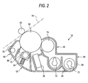
- FIG. 2 is a side view showing an image forming device used for the image forming apparatus according to the first exemplary embodiment of the invention
- FIG. 3 is a side view showing the positional relationship between image forming devices used in the first exemplary embodiment of the invention.
- FIG. 4 is a side view showing the positional relationship between image forming devices used in the second exemplary embodiment of the invention.
- FIG. 1 shows an image forming apparatus 10 according to an exemplary embodiment of the invention.
- the image forming apparatus 10 has an image forming apparatus main unit 12 , and in the image forming apparatus main unit 12 , an intermediate transfer belt 14 is disposed.
- an intermediate transfer belt 14 for example, four image forming devices 16 are disposed parallel to one another; thus, the image forming apparatus 10 forms a so-called tandem type.
- the image forming devices 16 form toner images of respective colors, yellow, magenta, cyan, and black, on the intermediate belt 14 .
- a sheet feeding device 18 is provided in a lower portion of the image forming apparatus main unit 12 .
- the sheet feeding device 18 has a sheet feeding cassette 20 to which sheets are loaded, a pickup roll 22 for picking up a sheet that has been loaded in this sheet feeding cassette 20 , and a feed roll 24 and a retard roll 26 for sending out the sheets while separating them.
- the sheet feeding cassette 20 is provided detachably from the image forming apparatus main unit 12 in such a manner that it can be drawn out frontward in the drawing. In the sheet feeding cassette 20 , sheets which are transfer sheets such as plain paper and OHP sheet, are loaded and accommodated.
- a sheet feeding path 28 is provided near one end of the image forming apparatus main unit 12 (near the left end in the drawing) along a substantially vertical direction. Conveying rolls 29 , resist rolls 30 , a second transfer roll 32 , a fixing device 34 , and discharge rolls 36 are provided on this sheet feeding path 28 .
- the resist rolls 30 temporarily holds the sheet that has been sent out to the sheet feeding path 28 , and sends it to the second transfer roll 32 with proper timing.
- the fixing device 34 includes a heating roll 34 a and a pressure roll 34 b that apply heat and pressure to the sheet that is passing through the heating roll 34 a and the pressure roll 34 b to fix a toner image onto the sheet.
- a discharge tray part 38 is provided at the upper portion of the image forming apparatus main unit 12 .
- the sheet on which a toner image has been fixed is discharged by the above-mentioned discharge rolls 36 onto the discharge tray part 38 , and is stacked on the discharge tray part 38 .
- the sheets in the sheet feeding cassette 20 are passed through the C-shaped path one after another and are discharged to the discharge tray part 38 .
- the toner bottles 40 are provided in the other end portion of the image forming apparatus main unit 12 (in the right end portion in the drawing).
- the toner bottles 40 accommodate toners of yellow, magenta, cyan, and black, respectively.
- the toner bottles 40 are configured to feed the toners to the image forming devices 16 via toner feeding paths, which are not shown in the drawing.
- the intermediate transfer belt 14 is supported by plural conveying rolls 42 , and the belt surface on which the above-described image forming devices 16 are provided is tilted with respect to a horizontal direction.
- One of the conveying rolls 42 forms a backup roll of the second transfer roll 32 .
- An intermediate belt cleaning device 44 is disposed in the vicinity of the upper end of the intermediate transfer belt 14 , and another one of the conveying rolls 42 forms a backup roll of the cleaning device 44 .
- a tension roll 46 is arranged above the intermediate transfer belt 14 so that an appropriate tension is applied to the intermediate transfer belt 14 by this tension roll 46 .
- Each of the image forming devices 16 includes an image forming unit 48 that face one surface of the intermediate transfer belt 14 , and a first transfer roll 50 provided on the back surface of the intermediate transfer belt 14 .
- the image forming unit 48 is freely detachable from the image forming apparatus main unit 12 , so that it can be drawn out frontward in the figure.
- FIG. 2 shows the details of each the image forming devices 16 .
- the image forming unit 48 has: a photosensitive drum 52 facing the intermediate transfer belt 14 ; a charging device 54 that charges the photosensitive drum 52 comprising for example, a roll; an exposing device 56 that forms a latent image on the photosensitive drum 52 comprising for example, an LED (light emitting diode); a developing device 58 that develops the latent image formed on the photosensitive drum 52 by the exposing device 56 using a toner; and a cleaning device 60 that removes the toner remaining on the photosensitive drum 52 after the transfer.
- the image forming unit 48 is constructed by coupling a photosensitive drum unit 62 and a developing unit 64 , which can be disassembled.
- the photosensitive drum unit 62 In the photosensitive drum unit 62 , the photosensitive drum 52 , the charging device 54 , the exposing device 56 , and the cleaning device 60 are accommodated in a first housing 66 .
- the developing unit 64 In the developing unit 64 , the developing device 58 is accommodated within a second housing 68 .
- the first housing 66 and the second housing 68 are detachably coupled to form the image forming unit 48 .
- the developing device 58 adopts, for example, a two-component system, and uses a developing agent comprising a toner and a carrier.
- the device has, for example, two augers 70 and 72 disposed horizontally parallel to each other, and a developing roll 74 disposed diagonally above the discharging-side auger 72 .
- the augers 70 and 72 stir the developing agent and feed it to the developing roll 74 .
- a magnetic brush originating from the carrier is formed on the developing roll 74 , and by this magnetic brush, the toner adhering to the carrier is conveyed so that the latent image on the photosensitive drum 52 is developed by the toner. Since the developing roll 74 is disposed above the augers 70 and 72 in the two-component system developing device 58 as in this exemplary embodiment, the developing agent is prevented from gathering and the developing agent can be stirred uniformly, whereby the development performance can be maintained.
- the cleaning device 60 includes a toner scraping-off part 76 comprising for example, a blade, and a collecting part 78 for collecting the toner that has been scraped off by the toner scraping-off part 76 .
- the intermediate transfer belt 14 and the photosensitive drum 52 rotate in synchronization with each other in opposite directions.
- the surface of the photosensitive drum 52 is charged by the charging device 54 , and a latent image is formed by the exposing device 56 .
- This latent image on the photosensitive drum 52 which has been formed by the exposing device 56 is developed by the developing device 58 .
- the toner image developed by the developing device 58 is transferred onto the intermediate transfer belt 14 by the first transfer roll 50 .
- the toner images of different colors formed by the respective image forming devices 16 are overlapped while the intermediate transfer belt 14 is moving.
- the sheets stacked in the sheet feeding cassette 20 of the sheet feeding device 18 are fed one by one to the sheet feeding path 28 by the pickup roll 22 , the feed roll 24 , the retard roll 26 , and so forth.
- the sheet fed to the sheet feeding path 28 is brought into contact with the resist rolls 30 , where it is held temporarily, and is then sent to the second transfer roll 32 with appropriate timing.
- the toner image on the intermediate transfer belt 14 is transferred to the sheet by this second transfer roll 32 .
- the sheet on which the toner image has been transferred is further sent to the fixing device 34 , where the toner image is fixed to the sheet by means of heat and pressure.
- the sheet on which the toner image has been fixed by the fixing device 34 is discharged to the discharge tray part 38 by the discharge rolls 36 .
- tandem-type image forming apparatus 10 tends to be large in size because, for example, four image forming devices 16 are lined up along the intermediate transfer belt 14 .
- size reduction is achieved by tilting the intermediate transfer belt 14 with respect to the horizontal direction and optimizing the layout of the plural image forming devices 16 relative to one another.
- FIG. 3 shows the positional relationship between the plural image forming devices 16 .
- the constituent components of a first image forming device 16 a are denoted by suffixing “a” to the reference numerals
- the constituent components of a second image forming device 16 b which is disposed adjacent to and above the first image forming device 16 a , are denoted by suffixing “b” to the reference numerals.
- a photosensitive drum unit 62 b of the second image forming device 16 b is disposed vertically above a developing device 58 a of the first image forming device 16 a so that a horizontal width B 2 of the photosensitive drum unit 62 b comes within a horizontal width A 1 of a developing device 58 a of the first image forming device 16 a .
- a photosensitive drum 52 b , a charging device 54 b , an exposing device 56 b , and a cleaning device 60 b of the second image forming device 16 b are disposed vertically above the first image forming device 16 a . Therefore, the apparatus is made compact corresponding to the size of the overlap.
- the whole of the photosensitive drum unit 62 b is vertically overlapped with the developing device 52 a ; however, only portions of the photosensitive drum 52 b , the charging device 54 b , and the exposing device 56 b may be vertically overlapped with the developing device 58 a.
- a first transfer roll 50 b of the second image forming device 16 b is disposed vertically above the developing device 58 a of the first image forming device 16 a so that the first transfer roll 50 b of the second image forming device 16 b comes within the horizontal width A of the developing device 58 a of the first image forming device 16 a .
- the whole of the first transfer roll 50 b is vertically overlapped with the developing device 58 a ; however, only a portion of the first transfer roll 50 b may be vertically overlapped with the developing device 58 a.
- FIG. 4 shows another exemplary embodiment.
- the constituent components of the first image forming device 16 a are denoted by suffixing “a” to the reference numerals
- the constituent components of the second image forming device 16 b which is disposed adjacent to and above the first image forming device 16 a
- suffixing “b” to the reference numerals
- the constituent components of a third image forming device 16 c which is disposed adjacent to and above the second image forming device 16 a , are denoted by suffixing “c” to the reference numerals.
- the horizontal width B 2 of the photosensitive drum unit 62 b of the second image forming device 16 b comes within the horizontal width Al of the developing device 58 a of the first image forming device 16 a .
- a portion of a horizontal width B 3 of a photosensitive drum unit 62 c of the third image forming device 16 c also comes within the horizontal width A 1 .
- the whole of the photosensitive drum unit 62 b and the first transfer roll 50 b of the second image forming device 16 b , and a portion of the cleaning device 60 c that is a portion of the photosensitive drum unit 62 c of the third image forming device 16 c , are disposed vertically within the horizontal width A 1 of the developing device 58 a of the first image forming device 16 a . Therefore, in this exemplary embodiment, the apparatus is made even more compact than the previously-described exemplary embodiment.
Landscapes
- Physics & Mathematics (AREA)
- General Physics & Mathematics (AREA)
- Color Electrophotography (AREA)
Abstract
Description
- 1. Technical Field
- The present invention relates to an image forming apparatus such as a printer, a facsimile, and a copier.
- 2. Related Art
- A tandem system is known as a type of image forming apparatus. The tandem system is such that, for example, four image forming units are disposed parallel to one another around a belt to form a color image. Although the tandem system can achieve high productivity, the apparatus tends to be large in size because four image forming units need to be aligned.
- According to an aspect of the present invention, an image forming apparatus includes a belt, plural photosensitive drums that face the belt, plural developing devices that develop plural latent images formed on the plural photosensitive drums using a developing agent, where the developing devices are disposed around the respective photosensitive drums, and plural image forming devices, where each one of the plural image forming devices includes one of the plural photosensitive drums and one of the plural developing devices, and the photosensitive drum of an adjacent one of the plural image forming devices is disposed vertically within a horizontal width of the developing device of one of the plural image forming devices.
- The foregoing belt may be an intermediate transfer belt or may be a conveying belt for conveying sheets.
- Exemplary embodiments of the present invention will be described in detail based on the following figures, wherein:
-
FIG. 1 is a side view showing an image forming apparatus according to the first exemplary embodiment of the invention; -
FIG. 2 is a side view showing an image forming device used for the image forming apparatus according to the first exemplary embodiment of the invention; -
FIG. 3 is a side view showing the positional relationship between image forming devices used in the first exemplary embodiment of the invention; and -
FIG. 4 is a side view showing the positional relationship between image forming devices used in the second exemplary embodiment of the invention. - Next, exemplary embodiments of the invention will be described with reference to the drawings.
-
FIG. 1 shows animage forming apparatus 10 according to an exemplary embodiment of the invention. Theimage forming apparatus 10 has an image forming apparatusmain unit 12, and in the image forming apparatusmain unit 12, anintermediate transfer belt 14 is disposed. For thisintermediate transfer belt 14, for example, fourimage forming devices 16 are disposed parallel to one another; thus, theimage forming apparatus 10 forms a so-called tandem type. Theimage forming devices 16 form toner images of respective colors, yellow, magenta, cyan, and black, on theintermediate belt 14. - A
sheet feeding device 18 is provided in a lower portion of the image forming apparatusmain unit 12. Thesheet feeding device 18 has asheet feeding cassette 20 to which sheets are loaded, apickup roll 22 for picking up a sheet that has been loaded in thissheet feeding cassette 20, and afeed roll 24 and aretard roll 26 for sending out the sheets while separating them. Thesheet feeding cassette 20 is provided detachably from the image forming apparatusmain unit 12 in such a manner that it can be drawn out frontward in the drawing. In thesheet feeding cassette 20, sheets which are transfer sheets such as plain paper and OHP sheet, are loaded and accommodated. - A
sheet feeding path 28 is provided near one end of the image forming apparatus main unit 12 (near the left end in the drawing) along a substantially vertical direction.Conveying rolls 29,resist rolls 30, asecond transfer roll 32, afixing device 34, anddischarge rolls 36 are provided on thissheet feeding path 28. Theresist rolls 30 temporarily holds the sheet that has been sent out to thesheet feeding path 28, and sends it to thesecond transfer roll 32 with proper timing. Thefixing device 34 includes aheating roll 34 a and apressure roll 34 b that apply heat and pressure to the sheet that is passing through theheating roll 34 a and thepressure roll 34 b to fix a toner image onto the sheet. - A
discharge tray part 38 is provided at the upper portion of the image forming apparatusmain unit 12. The sheet on which a toner image has been fixed is discharged by the above-mentioneddischarge rolls 36 onto thedischarge tray part 38, and is stacked on thedischarge tray part 38. Thus, the sheets in thesheet feeding cassette 20 are passed through the C-shaped path one after another and are discharged to thedischarge tray part 38. - Four
toner bottles 40, for example, are provided in the other end portion of the image forming apparatus main unit 12 (in the right end portion in the drawing). The toner bottles 40 accommodate toners of yellow, magenta, cyan, and black, respectively. Thetoner bottles 40 are configured to feed the toners to theimage forming devices 16 via toner feeding paths, which are not shown in the drawing. - The
intermediate transfer belt 14 is supported byplural conveying rolls 42, and the belt surface on which the above-describedimage forming devices 16 are provided is tilted with respect to a horizontal direction. One of theconveying rolls 42 forms a backup roll of thesecond transfer roll 32. An intermediatebelt cleaning device 44 is disposed in the vicinity of the upper end of theintermediate transfer belt 14, and another one of theconveying rolls 42 forms a backup roll of thecleaning device 44. In addition, atension roll 46 is arranged above theintermediate transfer belt 14 so that an appropriate tension is applied to theintermediate transfer belt 14 by thistension roll 46. - Each of the
image forming devices 16 includes animage forming unit 48 that face one surface of theintermediate transfer belt 14, and afirst transfer roll 50 provided on the back surface of theintermediate transfer belt 14. Theimage forming unit 48 is freely detachable from the image forming apparatusmain unit 12, so that it can be drawn out frontward in the figure. -
FIG. 2 shows the details of each theimage forming devices 16. Theimage forming unit 48 has: aphotosensitive drum 52 facing theintermediate transfer belt 14; acharging device 54 that charges thephotosensitive drum 52 comprising for example, a roll; anexposing device 56 that forms a latent image on thephotosensitive drum 52 comprising for example, an LED (light emitting diode); a developingdevice 58 that develops the latent image formed on thephotosensitive drum 52 by theexposing device 56 using a toner; and acleaning device 60 that removes the toner remaining on thephotosensitive drum 52 after the transfer. In this exemplary embodiment, theimage forming unit 48 is constructed by coupling aphotosensitive drum unit 62 and a developingunit 64, which can be disassembled. In thephotosensitive drum unit 62, thephotosensitive drum 52, thecharging device 54, theexposing device 56, and thecleaning device 60 are accommodated in afirst housing 66. In the developingunit 64, the developingdevice 58 is accommodated within asecond housing 68. Thefirst housing 66 and thesecond housing 68 are detachably coupled to form theimage forming unit 48. - The developing
device 58 adopts, for example, a two-component system, and uses a developing agent comprising a toner and a carrier. The device has, for example, twoaugers roll 74 disposed diagonally above the discharging-side auger 72. Theaugers roll 74. A magnetic brush originating from the carrier is formed on the developingroll 74, and by this magnetic brush, the toner adhering to the carrier is conveyed so that the latent image on thephotosensitive drum 52 is developed by the toner. Since the developingroll 74 is disposed above theaugers system developing device 58 as in this exemplary embodiment, the developing agent is prevented from gathering and the developing agent can be stirred uniformly, whereby the development performance can be maintained. - The
cleaning device 60 includes a toner scraping-offpart 76 comprising for example, a blade, and acollecting part 78 for collecting the toner that has been scraped off by the toner scraping-offpart 76. - In the above-described configuration, the
intermediate transfer belt 14 and thephotosensitive drum 52 rotate in synchronization with each other in opposite directions. The surface of thephotosensitive drum 52 is charged by thecharging device 54, and a latent image is formed by theexposing device 56. This latent image on thephotosensitive drum 52 which has been formed by theexposing device 56 is developed by the developingdevice 58. The toner image developed by the developingdevice 58 is transferred onto theintermediate transfer belt 14 by thefirst transfer roll 50. The toner images of different colors formed by the respectiveimage forming devices 16 are overlapped while theintermediate transfer belt 14 is moving. - Meanwhile, the sheets stacked in the
sheet feeding cassette 20 of thesheet feeding device 18 are fed one by one to thesheet feeding path 28 by thepickup roll 22, thefeed roll 24, the retard roll 26, and so forth. The sheet fed to thesheet feeding path 28 is brought into contact with theresist rolls 30, where it is held temporarily, and is then sent to thesecond transfer roll 32 with appropriate timing. Then, the toner image on theintermediate transfer belt 14 is transferred to the sheet by thissecond transfer roll 32. The sheet on which the toner image has been transferred is further sent to thefixing device 34, where the toner image is fixed to the sheet by means of heat and pressure. The sheet on which the toner image has been fixed by the fixingdevice 34 is discharged to thedischarge tray part 38 by the discharge rolls 36. - Such a tandem-type
image forming apparatus 10 tends to be large in size because, for example, fourimage forming devices 16 are lined up along theintermediate transfer belt 14. In this exemplary embodiment, size reduction is achieved by tilting theintermediate transfer belt 14 with respect to the horizontal direction and optimizing the layout of the pluralimage forming devices 16 relative to one another. -
FIG. 3 shows the positional relationship between the pluralimage forming devices 16. InFIG. 3 , the constituent components of a firstimage forming device 16 a are denoted by suffixing “a” to the reference numerals, and the constituent components of a secondimage forming device 16 b, which is disposed adjacent to and above the firstimage forming device 16 a, are denoted by suffixing “b” to the reference numerals. In this exemplary embodiment, aphotosensitive drum unit 62 b of the secondimage forming device 16 b is disposed vertically above a developingdevice 58 a of the firstimage forming device 16 a so that a horizontal width B2 of thephotosensitive drum unit 62 b comes within a horizontal width A1 of a developingdevice 58 a of the firstimage forming device 16 a. Thus, aphotosensitive drum 52 b, a chargingdevice 54 b, an exposingdevice 56 b, and acleaning device 60 b of the secondimage forming device 16 b are disposed vertically above the firstimage forming device 16 a. Therefore, the apparatus is made compact corresponding to the size of the overlap. In this exemplary embodiment, the whole of thephotosensitive drum unit 62 b is vertically overlapped with the developingdevice 52 a; however, only portions of thephotosensitive drum 52 b, the chargingdevice 54 b, and the exposingdevice 56 b may be vertically overlapped with the developingdevice 58 a. - In addition, a
first transfer roll 50 b of the secondimage forming device 16 b is disposed vertically above the developingdevice 58 a of the firstimage forming device 16 a so that thefirst transfer roll 50 b of the secondimage forming device 16 b comes within the horizontal width A of the developingdevice 58 a of the firstimage forming device 16 a. In this exemplary embodiment, the whole of thefirst transfer roll 50 b is vertically overlapped with the developingdevice 58 a; however, only a portion of thefirst transfer roll 50 b may be vertically overlapped with the developingdevice 58 a. -
FIG. 4 shows another exemplary embodiment. InFIG. 4 , the constituent components of the firstimage forming device 16 a are denoted by suffixing “a” to the reference numerals, the constituent components of the secondimage forming device 16 b, which is disposed adjacent to and above the firstimage forming device 16 a, are denoted by suffixing “b” to the reference numerals. The constituent components of a thirdimage forming device 16 c, which is disposed adjacent to and above the secondimage forming device 16 a, are denoted by suffixing “c” to the reference numerals. - In this exemplary embodiment, the horizontal width B2 of the
photosensitive drum unit 62 b of the secondimage forming device 16 b comes within the horizontal width Al of the developingdevice 58 a of the firstimage forming device 16 a. Moreover, a portion of a horizontal width B3 of aphotosensitive drum unit 62 c of the thirdimage forming device 16 c also comes within the horizontal width A1. In other words, the whole of thephotosensitive drum unit 62 b and thefirst transfer roll 50 b of the secondimage forming device 16 b, and a portion of thecleaning device 60 c that is a portion of thephotosensitive drum unit 62 c of the thirdimage forming device 16 c, are disposed vertically within the horizontal width A1 of the developingdevice 58 a of the firstimage forming device 16 a. Therefore, in this exemplary embodiment, the apparatus is made even more compact than the previously-described exemplary embodiment. - The foregoing description of the exemplary embodiments of the present invention has been provided for the purposes of illustration and description. It is not intended to be exhaustive or to limit the invention to the precise forms disclosed. Obviously, many modifications and variations will be apparent to practitioners skilled in the art. The exemplary embodiments were chosen and described in order to best explain the principles of the invention and its practical applications, thereby enabling others skilled in the art to understand the invention for various embodiments and with the various modifications as are suited to the particular use contemplated. It is intended that the scope of the invention be defined by the following claims and their equivalents.
Claims (18)
Applications Claiming Priority (2)
| Application Number | Priority Date | Filing Date | Title |
|---|---|---|---|
| JPP2005-358817 | 2005-12-13 | ||
| JP2005358817A JP5023484B2 (en) | 2005-12-13 | 2005-12-13 | Image forming apparatus |
Publications (2)
| Publication Number | Publication Date |
|---|---|
| US20070134026A1 true US20070134026A1 (en) | 2007-06-14 |
| US7742728B2 US7742728B2 (en) | 2010-06-22 |
Family
ID=38139525
Family Applications (1)
| Application Number | Title | Priority Date | Filing Date |
|---|---|---|---|
| US11/486,049 Expired - Fee Related US7742728B2 (en) | 2005-12-13 | 2006-07-14 | Image forming apparatus with compactly arranged image forming devices |
Country Status (4)
| Country | Link |
|---|---|
| US (1) | US7742728B2 (en) |
| JP (1) | JP5023484B2 (en) |
| KR (1) | KR100816347B1 (en) |
| CN (1) | CN1983050B (en) |
Cited By (2)
| Publication number | Priority date | Publication date | Assignee | Title |
|---|---|---|---|---|
| US20070248387A1 (en) * | 2006-04-25 | 2007-10-25 | Canon Kabushiki Kaisha | Image forming apparatus |
| RU2755870C1 (en) * | 2018-08-30 | 2021-09-22 | Хьюлетт-Паккард Дивелопмент Компани, Л.П. | Detecting the completion of the injection of cartridge toner to refill cartridge |
Citations (19)
| Publication number | Priority date | Publication date | Assignee | Title |
|---|---|---|---|---|
| US5160946A (en) * | 1991-07-19 | 1992-11-03 | Xerox Corporation | Image registration system |
| US5386286A (en) * | 1992-09-24 | 1995-01-31 | Kabushiki Kaisha Toshiba | Image forming apparatus |
| US6198890B1 (en) * | 1999-10-06 | 2001-03-06 | Aetas Technology Corporation | Electrophotographic color printing arrangement with inclined photoreceptor path |
| US20010055499A1 (en) * | 2000-06-14 | 2001-12-27 | Brother Kogyo Kabushiki Kaisha | Tandem type color image forming device having a plurality of process cartridges arrayed in running direction of intermediate image transfer member |
| US20020041781A1 (en) * | 2000-09-27 | 2002-04-11 | Motokazu Yasui | Apparatuses for color image formation, tandem color image formation and image formation |
| US6389260B1 (en) * | 1999-11-19 | 2002-05-14 | Sharp Kabushiki Kaisha | Tandem type color image forming device |
| US20020110388A1 (en) * | 2001-02-02 | 2002-08-15 | Canon Kabushiki Kaisha | Process cartridge, electrophotographic photosensitive drum, electrophotographic image forming apparatus and color electrophotographic image forming apparatus |
| US20030223784A1 (en) * | 2002-02-28 | 2003-12-04 | Tetsuo Yamanaka | Image forming apparatus |
| US20040101327A1 (en) * | 2002-08-06 | 2004-05-27 | Seiko Epson Corporation | Image carrier cartridge, exposure head , and image forming apparatus using these |
| US20040109704A1 (en) * | 2002-07-18 | 2004-06-10 | Seiko Epson Corporation | Image forming apparatus with transfer belt |
| US20040126150A1 (en) * | 2002-09-12 | 2004-07-01 | Yuusuke Noguchi | Desktop color image forming apparatus and method of making the same |
| US20040136747A1 (en) * | 2002-10-25 | 2004-07-15 | Matsushita Electric Industrial Co., Ltd. | Color image forming apparatus |
| US20040165910A1 (en) * | 2003-02-24 | 2004-08-26 | Brother Kogyo Kabushiki Kaisha | Image formation apparatus and photoreceptor cartridge |
| US20040190932A1 (en) * | 2003-03-28 | 2004-09-30 | Brother Kogyo Kabushiki Kaisha | Image forming apparatus |
| US20040208670A1 (en) * | 2002-07-26 | 2004-10-21 | Seiko Epson Corporation | Image forming apparatus with transfer belt |
| US20060083545A1 (en) * | 2004-10-19 | 2006-04-20 | Brother Kogyo Kabushiki Kaisha | Image-forming device |
| US7130567B2 (en) * | 2001-01-31 | 2006-10-31 | Ricoh Company, Ltd. | Toner container and image forming apparatus using the same |
| US7173646B2 (en) * | 2002-03-28 | 2007-02-06 | Canon Kabushiki Kaisha | Color image forming apparatus |
| US7203452B2 (en) * | 2000-09-14 | 2007-04-10 | Ricoh Company, Ltd. | Tandem image forming device having a side-by-side arrangement of image forming sections |
Family Cites Families (10)
| Publication number | Priority date | Publication date | Assignee | Title |
|---|---|---|---|---|
| JPH0323374U (en) | 1989-07-17 | 1991-03-11 | ||
| JP3023374B2 (en) | 1990-10-25 | 2000-03-21 | 株式会社リコー | Image processing device for each image area of copier |
| JP2001100488A (en) * | 1999-09-30 | 2001-04-13 | Casio Electronics Co Ltd | Color image forming equipment |
| JP2001209234A (en) | 2000-01-26 | 2001-08-03 | Ricoh Co Ltd | Color image forming equipment |
| CN1220117C (en) * | 2000-05-11 | 2005-09-21 | 株式会社理光 | Color image forming device and toner supply device |
| JP2002148892A (en) | 2000-11-14 | 2002-05-22 | Fuji Xerox Co Ltd | Image forming device |
| JP3470696B2 (en) | 2000-12-04 | 2003-11-25 | 日本電気株式会社 | Image recording device |
| JP2004061723A (en) * | 2002-07-26 | 2004-02-26 | Seiko Epson Corp | Image forming device |
| JP2004157448A (en) | 2002-11-08 | 2004-06-03 | Matsushita Electric Ind Co Ltd | Color image forming equipment |
| JP2004162807A (en) | 2002-11-13 | 2004-06-10 | Fujikin Inc | Lead type electromagnetically driven valve |
-
2005
- 2005-12-13 JP JP2005358817A patent/JP5023484B2/en not_active Expired - Fee Related
-
2006
- 2006-07-14 US US11/486,049 patent/US7742728B2/en not_active Expired - Fee Related
- 2006-08-02 KR KR1020060072891A patent/KR100816347B1/en active Active
- 2006-08-18 CN CN2006101114518A patent/CN1983050B/en not_active Expired - Fee Related
Patent Citations (20)
| Publication number | Priority date | Publication date | Assignee | Title |
|---|---|---|---|---|
| US5160946A (en) * | 1991-07-19 | 1992-11-03 | Xerox Corporation | Image registration system |
| US5386286A (en) * | 1992-09-24 | 1995-01-31 | Kabushiki Kaisha Toshiba | Image forming apparatus |
| US6198890B1 (en) * | 1999-10-06 | 2001-03-06 | Aetas Technology Corporation | Electrophotographic color printing arrangement with inclined photoreceptor path |
| US6389260B1 (en) * | 1999-11-19 | 2002-05-14 | Sharp Kabushiki Kaisha | Tandem type color image forming device |
| US20050030364A1 (en) * | 2000-06-14 | 2005-02-10 | Brother Kogyo Kabushiki Kaisha | Tandem type color image forming device having a plurality of process cartridges arrayed in running direction of intermediate image transfer member |
| US20010055499A1 (en) * | 2000-06-14 | 2001-12-27 | Brother Kogyo Kabushiki Kaisha | Tandem type color image forming device having a plurality of process cartridges arrayed in running direction of intermediate image transfer member |
| US7203452B2 (en) * | 2000-09-14 | 2007-04-10 | Ricoh Company, Ltd. | Tandem image forming device having a side-by-side arrangement of image forming sections |
| US20020041781A1 (en) * | 2000-09-27 | 2002-04-11 | Motokazu Yasui | Apparatuses for color image formation, tandem color image formation and image formation |
| US7130567B2 (en) * | 2001-01-31 | 2006-10-31 | Ricoh Company, Ltd. | Toner container and image forming apparatus using the same |
| US20020110388A1 (en) * | 2001-02-02 | 2002-08-15 | Canon Kabushiki Kaisha | Process cartridge, electrophotographic photosensitive drum, electrophotographic image forming apparatus and color electrophotographic image forming apparatus |
| US20030223784A1 (en) * | 2002-02-28 | 2003-12-04 | Tetsuo Yamanaka | Image forming apparatus |
| US7173646B2 (en) * | 2002-03-28 | 2007-02-06 | Canon Kabushiki Kaisha | Color image forming apparatus |
| US20040109704A1 (en) * | 2002-07-18 | 2004-06-10 | Seiko Epson Corporation | Image forming apparatus with transfer belt |
| US20040208670A1 (en) * | 2002-07-26 | 2004-10-21 | Seiko Epson Corporation | Image forming apparatus with transfer belt |
| US20040101327A1 (en) * | 2002-08-06 | 2004-05-27 | Seiko Epson Corporation | Image carrier cartridge, exposure head , and image forming apparatus using these |
| US20040126150A1 (en) * | 2002-09-12 | 2004-07-01 | Yuusuke Noguchi | Desktop color image forming apparatus and method of making the same |
| US20040136747A1 (en) * | 2002-10-25 | 2004-07-15 | Matsushita Electric Industrial Co., Ltd. | Color image forming apparatus |
| US20040165910A1 (en) * | 2003-02-24 | 2004-08-26 | Brother Kogyo Kabushiki Kaisha | Image formation apparatus and photoreceptor cartridge |
| US20040190932A1 (en) * | 2003-03-28 | 2004-09-30 | Brother Kogyo Kabushiki Kaisha | Image forming apparatus |
| US20060083545A1 (en) * | 2004-10-19 | 2006-04-20 | Brother Kogyo Kabushiki Kaisha | Image-forming device |
Cited By (3)
| Publication number | Priority date | Publication date | Assignee | Title |
|---|---|---|---|---|
| US20070248387A1 (en) * | 2006-04-25 | 2007-10-25 | Canon Kabushiki Kaisha | Image forming apparatus |
| US7822365B2 (en) * | 2006-04-25 | 2010-10-26 | Canon Kabushiki Kaisha | Image forming apparatus |
| RU2755870C1 (en) * | 2018-08-30 | 2021-09-22 | Хьюлетт-Паккард Дивелопмент Компани, Л.П. | Detecting the completion of the injection of cartridge toner to refill cartridge |
Also Published As
| Publication number | Publication date |
|---|---|
| CN1983050B (en) | 2012-09-05 |
| JP5023484B2 (en) | 2012-09-12 |
| KR20070062899A (en) | 2007-06-18 |
| KR100816347B1 (en) | 2008-03-24 |
| US7742728B2 (en) | 2010-06-22 |
| CN1983050A (en) | 2007-06-20 |
| JP2007163740A (en) | 2007-06-28 |
Similar Documents
| Publication | Publication Date | Title |
|---|---|---|
| US8295746B2 (en) | Image forming apparatus including a secondary transfer unit and a sheet guiding member | |
| US7848677B2 (en) | Image forming apparatus capable of preventing scattering of toner | |
| JP2010197458A (en) | Image forming apparatus | |
| CN100554107C (en) | Paper feeding device and image forming apparatus including the same | |
| US20120099908A1 (en) | Sheet transport device in the periphery of transfer position of image forming apparatus | |
| US7742728B2 (en) | Image forming apparatus with compactly arranged image forming devices | |
| JP5370032B2 (en) | Image forming apparatus | |
| US7751761B2 (en) | Image forming apparatus | |
| JP4515340B2 (en) | Image forming apparatus | |
| JP6670463B2 (en) | Paper feeder and image forming apparatus | |
| JP2004070152A (en) | Color image forming device | |
| US8666274B2 (en) | Image forming apparatus and cooling duct | |
| JP2007240893A (en) | Image forming apparatus | |
| JP2000298421A (en) | Image forming device | |
| JP5626570B2 (en) | Image forming apparatus | |
| JP5885639B2 (en) | Image forming apparatus | |
| JP2007163741A (en) | Image forming apparatus | |
| JP2011126649A (en) | Paper conveying device and image forming device | |
| JP2007316114A (en) | Image forming apparatus | |
| JP2001134046A (en) | Image forming device | |
| JP2006058817A (en) | Image forming apparatus | |
| JP2008134408A (en) | Image forming apparatus | |
| JP2011008178A (en) | Image forming device | |
| JP2009181006A (en) | Image forming apparatus | |
| HK1089821A1 (en) | Image forming apparatus that smoothly conveys transfer medium while suppressing pre-transfer |
Legal Events
| Date | Code | Title | Description |
|---|---|---|---|
| AS | Assignment |
Owner name: FUJI XEROX CO., LTD.,JAPAN Free format text: ASSIGNMENT OF ASSIGNORS INTEREST;ASSIGNORS:SATO, MASAHIRO;KITAMURA, ATSUYUKI;INAO, TSUKASA;REEL/FRAME:018107/0752 Effective date: 20060712 Owner name: FUJI XEROX CO., LTD., JAPAN Free format text: ASSIGNMENT OF ASSIGNORS INTEREST;ASSIGNORS:SATO, MASAHIRO;KITAMURA, ATSUYUKI;INAO, TSUKASA;REEL/FRAME:018107/0752 Effective date: 20060712 |
|
| STCF | Information on status: patent grant |
Free format text: PATENTED CASE |
|
| FPAY | Fee payment |
Year of fee payment: 4 |
|
| MAFP | Maintenance fee payment |
Free format text: PAYMENT OF MAINTENANCE FEE, 8TH YEAR, LARGE ENTITY (ORIGINAL EVENT CODE: M1552) Year of fee payment: 8 |
|
| FEPP | Fee payment procedure |
Free format text: MAINTENANCE FEE REMINDER MAILED (ORIGINAL EVENT CODE: REM.); ENTITY STATUS OF PATENT OWNER: LARGE ENTITY |
|
| LAPS | Lapse for failure to pay maintenance fees |
Free format text: PATENT EXPIRED FOR FAILURE TO PAY MAINTENANCE FEES (ORIGINAL EVENT CODE: EXP.); ENTITY STATUS OF PATENT OWNER: LARGE ENTITY |
|
| STCH | Information on status: patent discontinuation |
Free format text: PATENT EXPIRED DUE TO NONPAYMENT OF MAINTENANCE FEES UNDER 37 CFR 1.362 |
|
| FP | Lapsed due to failure to pay maintenance fee |
Effective date: 20220622 |