US2006133A - Pruning shears - Google Patents
Pruning shears Download PDFInfo
- Publication number
- US2006133A US2006133A US610674A US61067432A US2006133A US 2006133 A US2006133 A US 2006133A US 610674 A US610674 A US 610674A US 61067432 A US61067432 A US 61067432A US 2006133 A US2006133 A US 2006133A
- Authority
- US
- United States
- Prior art keywords
- head part
- plate
- blade
- bolt
- head
- Prior art date
- Legal status (The legal status is an assumption and is not a legal conclusion. Google has not performed a legal analysis and makes no representation as to the accuracy of the status listed.)
- Expired - Lifetime
Links
Images

Classifications
-
- A—HUMAN NECESSITIES
- A01—AGRICULTURE; FORESTRY; ANIMAL HUSBANDRY; HUNTING; TRAPPING; FISHING
- A01G—HORTICULTURE; CULTIVATION OF VEGETABLES, FLOWERS, RICE, FRUIT, VINES, HOPS OR SEAWEED; FORESTRY; WATERING
- A01G3/00—Cutting implements specially adapted for horticultural purposes; Delimbing standing trees
- A01G3/02—Secateurs; Flower or fruit shears
Definitions
- This invention relates to improvements in pruning shears, the general object of the invention being to provide a detachable blade. and also to provide means for preventing the pivot nut from working loose and to remove side strain on the bolts. Another object of the invention is to so position the pivot as to provide a draw out between the cutting members.
- Figure l is a side view of the complete device in open position.
- Fig. 2 is a section on line 2--2 of Fig. 1.
- Fig. 3 is a view of the blade.
- Fig. 4 is a view of the blade carrying member looking towards the inner face thereof.
- Fig. 5 is a view of the opposite member looking towards the outer side.
- Fig. 6 is a, view looking towards the opposite side of the member shown in Fig. 5.
- Fig. '7 is a view of the plate.
- the letter A indicates the hook carrying member and the letter B the blade operating member, each member consisting of a handle part and a head part, the head part of the member A being shown at l and the head part of the opposite member being shown at 2.
- the head part I is formed with the substantially hookshaped projection 3 which cooperates with the knife in the cutting operation.
- the knife is shown at i. and is provided with a head part 8 which has a hole 9 therein'through which .the bolt 4 passes and with a diagonally arranged elongated opening H! for receiving the similarly shaped projection l l on the inner face of the'part 2.
- This knife has its head part located between the head parts I and 2 and a plate l2 of the shape shown in Fig. 7 is fastened to the member B at the junction of the shank with the head part, by the two screws l3 and the bolt 4 also passes through a threaded hole H! in the plate.
- the plate I2 overlaps the major portion of the head part I of the member A so that the bolt 4 has one end supported by the part 2 of the memberB and its other end sup ported by the plate it which is attached to' a part 'ofthe member B.
- this plate provides strength for the cutting assembly of the shears and at the same time provides a direct bearing for the nut carrying end of the bolt andalso provides a bearing surface for the hook carrying member A. This plate also removes all side strain on the bolt.
- the major portions of the head parts I and 2 A are reduced in thickness so as to form the curved shoulder E6 on the member A and the irregular shaped shoulder i! on the member B, these shoulders being. so arranged relative to each other as to limit the opening and closing movement of shouider ii, a part of which the shoulder 19 forms a continuation.
- the head part of the blade is of the same thickness as the height of the shoulder i 9 so that the raised part i8 is flush with the head part of the blade when the blade is in position.
- the blade or knife can be detached from the other parts to facilitate its being sharpened and the plate l2 acts as a lock for the pivot bolt thereby avoiding the nut working loose, as the nut on the bolt does not come in contact with any working parts.
- the plate also removes side strain on the bolt and said plate can be detached when the parts become wornand that part of the plate which contacts the thickened part of portion 2 filed so that when the plate is put back in place the wear will be eliminated.
- the plate also acts as a'protector against pinching of the fingers as said plate will prevent, the fingers from entering the space formed by the members A and B when the members are in open position.
- the blade has three bearings so that there is no chance of the blade working loose tad tion abuts this shoulder i9 and portions of the as it will move with the part B through connection with said part through means of the .projection H and the slot Ill.
- the bolt does notturn so that there is no wear on the bolt or the hole in the blade.
- the member A is the only part that turns on the bolt.
- Pruning shears of the class described compris-' ing a pair of members, each having 'a head part and a handle part, the head part of one member belngof considerble width and the head part of the second member extending upwardly and forwardly, each head part being recessed on its inner face and having a hole in its upper part, a blade having a head part fitting in the space formed by the recesses and said head part of the blade having a hole adjacent its upper edge and adjacent the junction of said head part with the blade, the three holes registering, a bolt passing through the three holes, a non-circular projection on I the inner face of the head part of the second member and the head part of the blade having a non-circular opening for receiving the projection, said projection and hole being below and in rear of the holes in said head parts, a plate of substantially the same shape as the head part of the second member, screws fastening the lower end of the plate to the outer face of the lower end of the head part of the second member, said plate extending over the outer face of the
Landscapes
- Life Sciences & Earth Sciences (AREA)
- Biodiversity & Conservation Biology (AREA)
- Ecology (AREA)
- Forests & Forestry (AREA)
- Environmental Sciences (AREA)
- Scissors And Nippers (AREA)
Description
O. FOWLER June 25, 192.5.
PRUNING SHEARS Filed May 11, 1932 2 Sheets-Sheet l Inventor ode; FZwZer 4 Home y 0. FOWLER June 25, 1935.
PRUNING' SHEARS Filed May 11, 1952 I 2 Sheets-Sheet 2 Invcnlor @JQZ 2 awzer /I Home y Patented June 25, 1935 2,006,133 .PRUNING SHEARS Qdel Fowler, Palisade, 0010. Application May 1 1 1932,.Serial No. 610,674
UNITED, STATES PATENT OFFICE. I
' 1 Clai ml (o 30-11) This invention relates to improvements in pruning shears, the general object of the invention being to provide a detachable blade. and also to provide means for preventing the pivot nut from working loose and to remove side strain on the bolts. Another object of the invention is to so position the pivot as to provide a draw out between the cutting members. I
This invention also consists in certain other features of construction and in the combination and arrangement of the several parts to be hereinafter fully described, illustrated in the accompanying drawings and specifically pointed out in the appended claim.
In describing the invention in detail, reference will be had to the accompanying drawings wherc in like characters denote like or corresponding parts throughout the several views, and in which:-
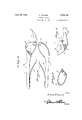
Figure l is a side view of the complete device in open position.
Fig. 2 is a section on line 2--2 of Fig. 1.
Fig. 3 is a view of the blade.
Fig. 4 is a view of the blade carrying member looking towards the inner face thereof. v
Fig. 5 is a view of the opposite member looking towards the outer side.
Fig. 6 is a, view looking towards the opposite side of the member shown in Fig. 5.
Fig. '7 is a view of the plate.
In these drawings, the letter A indicates the hook carrying member and the letter B the blade operating member, each member consisting of a handle part and a head part, the head part of the member A being shown at l and the head part of the opposite member being shown at 2. The head part I is formed with the substantially hookshaped projection 3 which cooperates with the knife in the cutting operation. The two head parts are. pivotally connected by the bolt =1 which passes thru an opening 5 in the head part i and through an opening 6 in the head part 2. The knife is shown at i. and is provided with a head part 8 which has a hole 9 therein'through which .the bolt 4 passes and with a diagonally arranged elongated opening H! for receiving the similarly shaped projection l l on the inner face of the'part 2. This knife has its head part located between the head parts I and 2 and a plate l2 of the shape shown in Fig. 7 is fastened to the member B at the junction of the shank with the head part, by the two screws l3 and the bolt 4 also passes through a threaded hole H! in the plate. As shown in Figure 2, the plate I2 overlaps the major portion of the head part I of the member A so that the bolt 4 has one end supported by the part 2 of the memberB and its other end sup ported by the plate it which is attached to' a part 'ofthe member B. -Thus this plate provides strength for the cutting assembly of the shears and at the same time provides a direct bearing for the nut carrying end of the bolt andalso provides a bearing surface for the hook carrying member A. This plate also removes all side strain on the bolt.
Springs 05 on the handle parts tend to hold the device in open position as shown in Fig. 1. The blade is of the shape shown in Fig. 3 and its curved cutting edge will cooperate with the part 3 in the cutting operation.
The major portions of the head parts I and 2 A are reduced in thickness so as to form the curved shoulder E6 on the member A and the irregular shaped shoulder i! on the member B, these shoulders being. so arranged relative to each other as to limit the opening and closing movement of shouider ii, a part of which the shoulder 19 forms a continuation. The head part of the blade is of the same thickness as the height of the shoulder i 9 so that the raised part i8 is flush with the head part of the blade when the blade is in position. i
As will be seen, the blade or knife can be detached from the other parts to facilitate its being sharpened and the plate l2 acts as a lock for the pivot bolt thereby avoiding the nut working loose, as the nut on the bolt does not come in contact with any working parts. The plate also removes side strain on the bolt and said plate can be detached when the parts become wornand that part of the plate which contacts the thickened part of portion 2 filed so that when the plate is put back in place the wear will be eliminated. The plate also acts as a'protector against pinching of the fingers as said plate will prevent, the fingers from entering the space formed by the members A and B when the members are in open position.
The blade has three bearings so that there is no chance of the blade working loose tad tion abuts this shoulder i9 and portions of the as it will move with the part B through connection with said part through means of the .projection H and the slot Ill. The bolt does notturn so that there is no wear on the bolt or the hole in the blade. The member A is the only part that turns on the bolt.
The bolt being offset about three-quarters of an inch from center of handles and about onehalf inch in ahead of center gives more leverage on handle and also gives about three-quarters that such changes fall within the scope of the appended claim.
Having thus described my invention, what I claim as new is:
Pruning shears of the class described compris-' ing a pair of members, each having 'a head part and a handle part, the head part of one member belngof considerble width and the head part of the second member extending upwardly and forwardly, each head part being recessed on its inner face and having a hole in its upper part, a blade having a head part fitting in the space formed by the recesses and said head part of the blade having a hole adjacent its upper edge and adjacent the junction of said head part with the blade, the three holes registering, a bolt passing through the three holes, a non-circular projection on I the inner face of the head part of the second member and the head part of the blade having a non-circular opening for receiving the projection, said projection and hole being below and in rear of the holes in said head parts, a plate of substantially the same shape as the head part of the second member, screws fastening the lower end of the plate to the outer face of the lower end of the head part of the second member, said plate extending over the outer face of the head part of the first member and having a threaded hole in its upper end for receiving the threaded part of the bolt, a nut threadedon the bolt and contacting the plate, and a hook extending from the head part of the first member.
ODEL FOWLER.
Priority Applications (1)
| Application Number | Priority Date | Filing Date | Title |
|---|---|---|---|
| US610674A US2006133A (en) | 1932-05-11 | 1932-05-11 | Pruning shears |
Applications Claiming Priority (1)
| Application Number | Priority Date | Filing Date | Title |
|---|---|---|---|
| US610674A US2006133A (en) | 1932-05-11 | 1932-05-11 | Pruning shears |
Publications (1)
| Publication Number | Publication Date |
|---|---|
| US2006133A true US2006133A (en) | 1935-06-25 |
Family
ID=24445979
Family Applications (1)
| Application Number | Title | Priority Date | Filing Date |
|---|---|---|---|
| US610674A Expired - Lifetime US2006133A (en) | 1932-05-11 | 1932-05-11 | Pruning shears |
Country Status (1)
| Country | Link |
|---|---|
| US (1) | US2006133A (en) |
Cited By (3)
| Publication number | Priority date | Publication date | Assignee | Title |
|---|---|---|---|---|
| US2713719A (en) * | 1953-08-27 | 1955-07-26 | Coplen George | Shears for cutting tubular sheet metal articles |
| US2942341A (en) * | 1959-01-09 | 1960-06-28 | Randolph Harry Beckham | Hand shears, scissors and like tools |
| US6370780B1 (en) | 2000-12-29 | 2002-04-16 | Duane D. Robertson | Spring-biased cutting tool for plastic pipes |
-
1932
- 1932-05-11 US US610674A patent/US2006133A/en not_active Expired - Lifetime
Cited By (3)
| Publication number | Priority date | Publication date | Assignee | Title |
|---|---|---|---|---|
| US2713719A (en) * | 1953-08-27 | 1955-07-26 | Coplen George | Shears for cutting tubular sheet metal articles |
| US2942341A (en) * | 1959-01-09 | 1960-06-28 | Randolph Harry Beckham | Hand shears, scissors and like tools |
| US6370780B1 (en) | 2000-12-29 | 2002-04-16 | Duane D. Robertson | Spring-biased cutting tool for plastic pipes |
Similar Documents
| Publication | Publication Date | Title |
|---|---|---|
| US2244577A (en) | Mill hammer | |
| US2284664A (en) | Shears | |
| US2213071A (en) | Putty knife | |
| US2264840A (en) | Tin snips | |
| US2158277A (en) | Shears | |
| US2169557A (en) | Hand hoe | |
| US2395897A (en) | Pinking shears | |
| US2006133A (en) | Pruning shears | |
| US533219A (en) | Pocket-knife | |
| US2093987A (en) | Metal cutting tool | |
| US2758372A (en) | Scissors | |
| US3052026A (en) | Scissors, shears and like implements | |
| US2000852A (en) | Shears | |
| US2131780A (en) | Adenotome | |
| US1662108A (en) | Pliers | |
| US2803058A (en) | Tin snips | |
| US2005694A (en) | Hedge shears | |
| US1572546A (en) | Pruner | |
| US2082502A (en) | Scissors | |
| US2059074A (en) | Shears | |
| US2033216A (en) | Shears | |
| US2556367A (en) | Device for cutting hard materials | |
| US2567129A (en) | Metal-cutting shears | |
| US812528A (en) | Pruning implement. | |
| US784069A (en) | Shears. |