US20040000278A1 - Rocker arm and manufacturing method thereof - Google Patents
Rocker arm and manufacturing method thereof Download PDFInfo
- Publication number
- US20040000278A1 US20040000278A1 US10/602,775 US60277503A US2004000278A1 US 20040000278 A1 US20040000278 A1 US 20040000278A1 US 60277503 A US60277503 A US 60277503A US 2004000278 A1 US2004000278 A1 US 2004000278A1
- Authority
- US
- United States
- Prior art keywords
- pair
- valve guide
- rocker arm
- valve
- predetermined
- Prior art date
- Legal status (The legal status is an assumption and is not a legal conclusion. Google has not performed a legal analysis and makes no representation as to the accuracy of the status listed.)
- Granted
Links
- 238000004519 manufacturing process Methods 0.000 title claims description 16
- 238000000034 method Methods 0.000 claims description 8
- 238000003825 pressing Methods 0.000 claims description 8
- 239000002184 metal Substances 0.000 claims description 7
- 239000013067 intermediate product Substances 0.000 description 23
- 238000000465 moulding Methods 0.000 description 9
- 238000003754 machining Methods 0.000 description 7
- 239000007769 metal material Substances 0.000 description 3
- 230000002093 peripheral effect Effects 0.000 description 3
- 238000003780 insertion Methods 0.000 description 2
- 230000037431 insertion Effects 0.000 description 2
- 239000000047 product Substances 0.000 description 2
- 229910000831 Steel Inorganic materials 0.000 description 1
- 238000000137 annealing Methods 0.000 description 1
- 230000015572 biosynthetic process Effects 0.000 description 1
- 238000004140 cleaning Methods 0.000 description 1
- 238000005480 shot peening Methods 0.000 description 1
- 239000010959 steel Substances 0.000 description 1
Images


Classifications
-
- B—PERFORMING OPERATIONS; TRANSPORTING
- B21—MECHANICAL METAL-WORKING WITHOUT ESSENTIALLY REMOVING MATERIAL; PUNCHING METAL
- B21K—MAKING FORGED OR PRESSED METAL PRODUCTS, e.g. HORSE-SHOES, RIVETS, BOLTS OR WHEELS
- B21K1/00—Making machine elements
- B21K1/20—Making machine elements valve parts
- B21K1/205—Making machine elements valve parts rocker arms
-
- F—MECHANICAL ENGINEERING; LIGHTING; HEATING; WEAPONS; BLASTING
- F01—MACHINES OR ENGINES IN GENERAL; ENGINE PLANTS IN GENERAL; STEAM ENGINES
- F01L—CYCLICALLY OPERATING VALVES FOR MACHINES OR ENGINES
- F01L1/00—Valve-gear or valve arrangements, e.g. lift-valve gear
- F01L1/12—Transmitting gear between valve drive and valve
- F01L1/18—Rocking arms or levers
- F01L1/185—Overhead end-pivot rocking arms
-
- Y—GENERAL TAGGING OF NEW TECHNOLOGICAL DEVELOPMENTS; GENERAL TAGGING OF CROSS-SECTIONAL TECHNOLOGIES SPANNING OVER SEVERAL SECTIONS OF THE IPC; TECHNICAL SUBJECTS COVERED BY FORMER USPC CROSS-REFERENCE ART COLLECTIONS [XRACs] AND DIGESTS
- Y10—TECHNICAL SUBJECTS COVERED BY FORMER USPC
- Y10T—TECHNICAL SUBJECTS COVERED BY FORMER US CLASSIFICATION
- Y10T29/00—Metal working
- Y10T29/49—Method of mechanical manufacture
- Y10T29/49229—Prime mover or fluid pump making
- Y10T29/49295—Push rod or rocker arm making
Definitions
- the present invention relates to a rocker arm and a manufacturing method thereof.
- the rocker arm includes a body and a roller pivotally attached to the body through a support shaft.
- the body includes a pair of side walls opposed to each other in the axial direction and a pair of connecting walls for connecting the side walls with each other at both end portions of the side walls in the longitudinal direction.
- the valve engaging portion is constituted by valve guide walls, which are arranged at one end side of the side walls in the longitudinal direction, and a connecting wall arranged on one end side for connecting both the valve guide walls.
- the pivot receiving portion for receiving an upper end portion of the lash adjuster is formed on the connecting wall on the other end side of the side walls in the longitudinal direction.
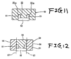
- the body of the above rocker arm is manufactured by means of press forming in some cases. Concerning the procedure of manufacturing the body, one metallic sheet is punched by means of press forming so as to form it into a metallic sheet member having a predetermined shape. Then, this metallic sheet member is folded and formed into a substantial U-shape as shown in FIG. 11. After that, in this U-shaped metallic sheet member, a valve engaging portion is formed by using the die 50 having a predetermined shape. This die 50 is integrally formed to have a recess portion 53 into which a pair of side walls 51 , which are opposed to each other, and the connecting walls 52 are inserted.
- the die 50 is divided as shown in FIG. 12.
- This die 50 includes: a pair of outer dies 55 to push the side walls 51 laterally; and an inner die 56 , separated from these outer dies 55 , to form the connecting wall 52 between the outer dies 55 and the inner die 56 .
- These outer dies 55 and the inner die 56 are divided on the dividing lines 57 that is formed at a portion corresponding to the corner angle portion of the side wall 51 . According to the constitution, it is possible to prevent the occurrence of cracks in the die 50 .
- the object of the invention is to provide a rocker arm in which the molding flash is not detached from the rocket arm and does not affects the peripheral parts.
- the invention is characterized by having the following arrangement.
- a rocker arm for opening and closing a valve comprising:
- valve engaging portion provided at the body, with which the valve is engaged, the valve engaging portion including,
- a pair of excess thickness portions formed on the pair of valve guide walls, respectively, the pair of excess thickness portions being formed by portions of the pair of valve guide walls which plastically flow when the pair of valve guide walls are formed by dies, respectively.
- Aspect 2 The rocker arm according to the aspect 1, wherein
- the connecting wall connects the pair of valve guide walls with each other in a first direction
- the pair of excess thickness portions are projected from the pair of valve guide wall in a second direction substantially perpendicular to the first direction, respectively.
- each of the pair of valve guide walls includes a side surface to which the connecting wall is connected, and a bottom surface substantially parallel to a bottom surface of the connecting wall,
- the pair of excess thickness portions are formed on the bottom surfaces of the pair of valve guide walls.
- Aspect 4 The rocker arm according to the aspect 3, wherein
- the bottom surfaces of the pair of valve guide walls is projected from the bottom surface of the connecting wall in the second direction.
- Aspect 5 The rocker arm according to the aspect 3, wherein
- the pair of excess thickness portions are extended along the bottom surfaces of the pair of valve guide walls in a third direction substantially perpendicular to the first and second directions.
- Aspect 6 The rocker arm according to the aspect 3, wherein a width of each of the pair of excess thickness portions is set to be less than half and more than one-fifth of a width of the bottom surface of each of the pair of valve guide walls.
- a method of manufacturing a rocker arm for opening and closing a valve comprising the steps of:
- a metal sheet including a pair of predetermined valve guide wall regions opposed to each other and a predetermined connecting wall region connecting the pair of predetermined valve guide wall regions with each other;
- FIG. 1 is a side view showing a state of the use of the rocker arm of the embodiment of the present invention.
- FIG. 2 is a plan view showing a first intermediate product in the case of manufacturing the rocker arm of the embodiment of the present invention.
- FIG. 3 is a perspective view showing a second intermediate product in the case of manufacturing the rocker arm of the embodiment of the present invention.
- FIG. 4 is a perspective view showing a third intermediate product in the case of manufacturing the rocker arm of the embodiment of the present invention.
- FIG. 5 is a perspective view showing a fourth intermediate product in the case of manufacturing the rocker arm of the embodiment of the present invention.
- FIG. 6 is a process drawing of manufacturing a valve engaging portion of the rocker arm of the embodiment of the present invention.
- FIG. 7 is a perspective view showing a fifth intermediate product in the case of manufacturing the rocker arm of the embodiment of the present invention.
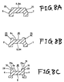
- FIGS. 8A to 8 C are views showing a change in the shape of the valve engaging portion in the manufacturing process.
- FIG. 9 is a perspective view of the body of the rocker arm that is a product.
- FIG. 10 is an enlarged view showing the continuity of a metal flow in the valve engaging portion.
- FIG. 11 is a front view showing a profile of a conventional die.
- FIG. 12 is a front view showing a profile of another conventional die.
- FIG. 1 is a side view showing a state of use of the rocker arm of the present invention
- FIG. 2 is a plan view showing a first intermediate product in the case of manufacturing the rocker arm
- FIG. 3 is a perspective view of the second intermediate product
- FIG. 4 is a perspective view of the third intermediate product
- FIG. 5 is a perspective view of the fourth intermediate product
- FIG. 6 is a process drawing of manufacturing a valve engaging portion
- FIG. 7 is a perspective view of the fifth intermediate product
- FIGS. 8A to 8 C are views showing a change in the shape of the valve engaging portion in the manufacturing process
- FIG. 9 is a perspective view of the rocker arm that is a product
- FIG. 10 is an enlarged view showing the continuity of a metal flow in the valve engaging portion.
- this rocker arm 1 is of the end pivot type having the constitution in which the body 4 is tilted by the rotation of the cam 3 as one end side in the longitudinal direction of the rocker arm supported by the lash adjuster 2 a serves as a fulcrum. According to the tilting motion of this rocker arm 1 , a valve not shown in the drawing is opened and closed.
- This rocker arm 1 includes the body 4 and the roller 5 .
- This body 4 includes a pair of side walls 6 , 7 which are opposed to each other in the axial direction of the roller 5 .
- the body 4 further includes the connecting walls 8 , 9 for connecting the side walls 6 , 7 with each other, arranged on one end side and the other end side in the longitudinal direction.
- the body 4 further includes the valve engaging portion 10 arranged on one end side in the longitudinal direction.
- the body 4 further includes the pivot receiving portion 11 arranged on the other end side in the longitudinal direction.
- In the middle of the side walls 6 , 7 there are formed insertion holes 13 , 14 into which the support shaft 12 is inserted.
- the valve engaging portion 10 includes the valve guide walls 28 , 29 formed by deforming one portion of the side walls 6 , 7 , and the connecting wall 8 .
- a continuous metal flow is formed among the valve guide walls 28 , 29 and the connecting wall 8 in the valve engaging portion 10 .
- the valve guide walls 28 , 29 are used for guiding the valve stem 2 B.
- On the bottom faces 28 a , 29 a of the valve guide walls 28 , 29 the excess thickness portions 35 are formed.
- the connecting wall 9 on the other end side in the longitudinal direction has the aforementioned pivot receiving portion 11 for receiving an upper end portion of the lash adjuster 2 .
- the roller 5 is arranged in such a manner that one portion of the roller 5 is projected from the opening 15 farmed in the bottom portion between the two connecting walls 8 , 9 in the body 4 .
- This roller 5 is pivotally supported by the support shaft 12 via a plurality of needle rollers 5 a.
- one metallic sheet (steel sheet) is punched by means for press forming to obtain a metallic sheet member M of a predetermined shape, at both side edges of which the arcuate portions 16 are provided.
- the metallic sheet member M is punched so as to form the opening 15 at the substantial center. Therefore, the metallic sheet member M is formed into a shape having the predetermined side wall regions 6 A, 7 A and the predetermined connecting wall regions 8 A, 9 A.
- a central region of the predetermined connecting wall region 9 A on the other end side is subjected to drawing and formed into the hemispherical pivot receiving portion 11 . Regions close to the arcuate portions 16 of this metallic sheet member M are punched into the insertion holes 13 , 14 . In this way, the first intermediate product 17 shown in FIG. 2 is provided.
- Folding is conducted on the first intermediate product 17 at positions shown by the broken lines “a” and “b” in FIG. 2. In this way, the second intermediate product 18 shown in FIG. 3 is provided.
- this second intermediate product 18 is formed into a substantial U-shape when a view is taken from the front.
- This second intermediate product 18 includes: a pair of side walls 6 , 7 which are arranged being opposed to each other in the axial direction; the predetermined connecting wall region 8 A for connecting the predetermined valve guide wall regions 8 B, 8 C corresponding to one end side of both side walls 6 , 7 ; and the connecting wall 9 for connecting the other end sides of the both side walls 6 , 7 .
- the predetermined connecting wall region 9 A becomes the connecting wall 9 as it is.
- a predetermined die is set so that the intermediate portions of both side walls 6 , 7 in the longitudinal direction of the above second intermediate product 18 can be restricted, and portions corresponding to the lower side of the predetermined valve guide wall regions 8 B, 8 C are pushed from both sides toward the inside (in the cross direction) by the first dies 26 , 27 (shown in FIG. 6), the cross sections of which are formed into a substantial rectangle. Therefore, the predetermined connecting wall region 8 A is compressed and formed in the cross direction. Due to the above compressive forming, the step-like side portions 25 are formed in the predetermined valve guide wall regions 8 B, 8 C. According to that, the wall thickness of the predetermined connecting wall region 8 A is increased, and the third intermediate product 19 shown in FIG. 4 can be provided. When necessary, softening annealing is conducted on the third intermediate product 19 so as to remove the internal stress.
- the second die 24 for forming a groove which is different from the first dies 26 , 27 , is pushed at the intermediate positions on the lower face side of the predetermined valve guide wall regions 8 B, 8 C, that is, the second die 24 for forming a groove is pushed at the predetermined connecting wall region 8 A, so that a central region on the lower face side of the predetermined connecting wall region 8 A is deformed being recessed upward (in the height direction).
- both sides of the recessed portion that is, the predetermined valve guide wall regions 8 B, 8 C are made to plastically flow downward so that the height can be increased, and the groove 30 is formed by the predetermined connecting wall region 8 A and the predetermined valve guide wall regions 8 B, 8 C.
- the fourth intermediate product 20 shown in FIG. 5 is provided.
- the second die 24 is formed into a step-like shape in which the width in the axial direction is reduced on the forward end side. Therefore, the forward end portion 31 of the second die 24 is used for engaging between the predetermined valve guide wall regions 8 B, 8 C so that the groove 30 (the forward end portion 31 ) can be formed.
- the width of the intermediate portion 32 of the second die 24 is smaller than the width between the sides of the predetermined valve guide wall regions 8 B, 8 C.
- the width of the base end portion 33 of the second die 24 is set to be the same as the width between the sides 28 , 29 of the valve guide walls 28 , 29 .
- the gaps 34 for forming the excess thickness portion is provided between the first dies 26 , 27 and the intermediate portion 32 of the second die 24 .
- the second die 24 is further pushed and the predetermined connecting wall region 8 A is gradually moved upward.
- the depth of the groove 30 is being gradually increased so that the predetermined connecting wall region 8 A can be located at a predetermined position in the middle in the height direction of the predetermined valve guide wall regions 8 B, 8 C
- the height of the predetermined valve guide wall regions 8 B, 8 C is gradually increased.
- the forward end face 32 a of the intermediate portion 32 of the second die 24 pushes the bottom faces 28 a , 29 a of the valve guide walls 28 , 29 .
- FIG. 6 is a view showing the fifth intermediate product 21 .
- FIGS. 8A to 8 C show a change in the cross section of the valve engaging portion 10 in the process of machining.
- the reason why machining in the cross direction and machining for forming the groove are successively conducted by a plurality of times is to prevent the metal flow 40 , which flows between the valve guide walls 28 , 29 (both side walls 6 , 7 ) and the connecting wall 8 , from being cut off.
- the final groove forming is conducted by using a pushing punch for finishing not shown in the drawing in such a manner that the bottom face 8 a of the predetermined connecting wall region 8 A is formed into a curved face having a predetermined radius of curvature. Therefore, the predetermined connecting wall region 8 A becomes the connecting wall 8 , and the predetermined valve guide wall regions 8 B, 8 C become the valve guide walls 28 , 29 . In this way, the body 4 having the valve engaging portion 10 , the depth of which is sufficiently large, is provided as shown in FIGS. 1 to 9 .
- first dies 26 , 27 and the second die 24 which is separated from the first dies 26 , 27 , are provided in the case of machining the valve engaging portion 10 , it is possible to avoid the occurrence of a case in which stress concentration is caused in one portion of the die and the life of the die is shortened like the conventional die.
- the gap 34 for forming the excess thickness portion is provided between the first dies 26 , 27 and the intermediate portion 32 of the second die 24 , and the excess thickness portion 35 , which is attached to the valve guide walls 28 , 29 , the size of which is larger than that of the conventional molding flash and the mechanical strength of which is higher than that of the conventional molding flash, is formed in the valve guide walls 28 , 29 .
- This excess thickness portion 35 is not removed by means of shot peening or cleaning conducted by the barrel device after the formation of the body 4 . Even when the rocker arm 1 is used, this excess thickness portion is not disengaged from the valve guide walls 28 , 29 .
- a width of each the excess thickness portion 35 is set to be less than half and more than one fifth of a width of each bottom surface 28 a , 29 a.
- valve engaging portion 10 When the valve engaging portion 10 is formed, a pushing force given to the first dies 26 , 27 and the second die 24 is adjusted in the process of machining in the cross direction and forming a groove, and the machining is conducted by a plurality of times. Therefore, as shown in FIG. 10, it is possible to prevent the metal flow 40 between both side walls 6 , 7 and the connecting wall 8 from being cut off. Therefore, it is possible to ensure the rigidity of the valve engaging portion 10 , and the rocker arm 1 of stable quality can be provided.
Landscapes
- Engineering & Computer Science (AREA)
- Mechanical Engineering (AREA)
- General Engineering & Computer Science (AREA)
- Valve-Gear Or Valve Arrangements (AREA)
- Forging (AREA)
Abstract
A gap (34) for forming an excess thickness portion is provided between a pair of first dies (26, 27) and a intermediate portion (32) of the second die (24), and an excess thickness portion (35) is formed in bottom portions of the valve guide walls (28, 29) of valve guide walls.
Description
- The present invention relates to a rocker arm and a manufacturing method thereof.
- In general, the rocker arm includes a body and a roller pivotally attached to the body through a support shaft. The body includes a pair of side walls opposed to each other in the axial direction and a pair of connecting walls for connecting the side walls with each other at both end portions of the side walls in the longitudinal direction.
- The valve engaging portion is constituted by valve guide walls, which are arranged at one end side of the side walls in the longitudinal direction, and a connecting wall arranged on one end side for connecting both the valve guide walls. The pivot receiving portion for receiving an upper end portion of the lash adjuster is formed on the connecting wall on the other end side of the side walls in the longitudinal direction.
- The body of the above rocker arm is manufactured by means of press forming in some cases. Concerning the procedure of manufacturing the body, one metallic sheet is punched by means of press forming so as to form it into a metallic sheet member having a predetermined shape. Then, this metallic sheet member is folded and formed into a substantial U-shape as shown in FIG. 11. After that, in this U-shaped metallic sheet member, a valve engaging portion is formed by using the die 50 having a predetermined shape. This
die 50 is integrally formed to have arecess portion 53 into which a pair ofside walls 51, which are opposed to each other, and theconnecting walls 52 are inserted. - In the case of forming the valve engaging portion by using the
integral die 50 described above, there is a possibility that stress concentration is caused in the corner angle portion 53 a of therecess portion 53 when thedie 50 is given a force. Therefore, cracks tend to occur in the die 50 originating at the corner angle portion 53 a of therecess portion 53. - Therefore, it can be considered that the
die 50 is divided as shown in FIG. 12. This die 50 includes: a pair ofouter dies 55 to push theside walls 51 laterally; and aninner die 56, separated from theseouter dies 55, to form theconnecting wall 52 between theouter dies 55 and theinner die 56. Theseouter dies 55 and theinner die 56 are divided on thedividing lines 57 that is formed at a portion corresponding to the corner angle portion of theside wall 51. According to the constitution, it is possible to prevent the occurrence of cracks in the die 50. - However, in the case where the die 50 is divided into the
outer dies 55 andinner die 56 as described above, when a force is given to theouter dies 55 andinner die 56, there is a tendency that both thedies dies - Therefore, when the
valve guide walls 51 and theconnecting wall 52 are formed, metallic material may plastically flow and get into the gap formed between both thedies side wall 51. The thus formed molding flash can not be removed in the finishing work conducted in the later process in some cases. Therefore, the thus formed molding flash is separated from the body during the use of the rocker arm and attached to parts arranged in the periphery. - To solve the above problem, the object of the invention is to provide a rocker arm in which the molding flash is not detached from the rocket arm and does not affects the peripheral parts.
- In order to solve the aforesaid object, the invention is characterized by having the following arrangement.
- Aspect 1. A rocker arm for opening and closing a valve comprising:
- a body; and
- a valve engaging portion provided at the body, with which the valve is engaged, the valve engaging portion including,
- a pair of valve guide walls opposed to each other,
- a connecting wall connecting the pair of valve guide walls with each other, and
- a pair of excess thickness portions formed on the pair of valve guide walls, respectively, the pair of excess thickness portions being formed by portions of the pair of valve guide walls which plastically flow when the pair of valve guide walls are formed by dies, respectively.
- Aspect 2. The rocker arm according to the aspect 1, wherein
- the connecting wall connects the pair of valve guide walls with each other in a first direction, and
- the pair of excess thickness portions are projected from the pair of valve guide wall in a second direction substantially perpendicular to the first direction, respectively.
-
Aspect 3. The rocker arm according to the aspect 2, wherein - each of the pair of valve guide walls includes a side surface to which the connecting wall is connected, and a bottom surface substantially parallel to a bottom surface of the connecting wall,
- the pair of excess thickness portions are formed on the bottom surfaces of the pair of valve guide walls.
-
Aspect 4. The rocker arm according to theaspect 3, wherein - the bottom surfaces of the pair of valve guide walls is projected from the bottom surface of the connecting wall in the second direction.
-
Aspect 5. The rocker arm according to theaspect 3, wherein - the pair of excess thickness portions are extended along the bottom surfaces of the pair of valve guide walls in a third direction substantially perpendicular to the first and second directions.
-
Aspect 6. The rocker arm according to theaspect 3, wherein a width of each of the pair of excess thickness portions is set to be less than half and more than one-fifth of a width of the bottom surface of each of the pair of valve guide walls. -
Aspect 7. A method of manufacturing a rocker arm for opening and closing a valve, the method comprising the steps of: - providing a metal sheet including a pair of predetermined valve guide wall regions opposed to each other and a predetermined connecting wall region connecting the pair of predetermined valve guide wall regions with each other;
- pressing the pair of predetermined valve guide wall regions by a pair of first dies to approach each other in a first direction, respectively;
- pressing and recess a center portion of the connecting wall region by a second die in a second direction substantially perpendicular to the first direction; and
- forming a pair of excess thickness portions from portions of the pair of predetermined guide wall regions which plastically flow into gaps provided between the first and second dies according to the pressing motion to press the pair of predetermined valve guide wall regions and according to the pressing motion to press the predetermined connecting wall region.
- FIG. 1 is a side view showing a state of the use of the rocker arm of the embodiment of the present invention.
- FIG. 2 is a plan view showing a first intermediate product in the case of manufacturing the rocker arm of the embodiment of the present invention.
- FIG. 3 is a perspective view showing a second intermediate product in the case of manufacturing the rocker arm of the embodiment of the present invention.
- FIG. 4 is a perspective view showing a third intermediate product in the case of manufacturing the rocker arm of the embodiment of the present invention.
- FIG. 5 is a perspective view showing a fourth intermediate product in the case of manufacturing the rocker arm of the embodiment of the present invention.
- FIG. 6 is a process drawing of manufacturing a valve engaging portion of the rocker arm of the embodiment of the present invention.
- FIG. 7 is a perspective view showing a fifth intermediate product in the case of manufacturing the rocker arm of the embodiment of the present invention.
- FIGS. 8A to 8C are views showing a change in the shape of the valve engaging portion in the manufacturing process.
- FIG. 9 is a perspective view of the body of the rocker arm that is a product.
- FIG. 10 is an enlarged view showing the continuity of a metal flow in the valve engaging portion.
- FIG. 11 is a front view showing a profile of a conventional die.
- FIG. 12 is a front view showing a profile of another conventional die.
- Referring to the drawings, the rocker arm of the present invention will be explained as follows. FIG. 1 is a side view showing a state of use of the rocker arm of the present invention, FIG. 2 is a plan view showing a first intermediate product in the case of manufacturing the rocker arm, FIG. 3 is a perspective view of the second intermediate product, FIG. 4 is a perspective view of the third intermediate product, FIG. 5 is a perspective view of the fourth intermediate product, FIG. 6 is a process drawing of manufacturing a valve engaging portion, FIG. 7 is a perspective view of the fifth intermediate product, FIGS. 8A to 8C are views showing a change in the shape of the valve engaging portion in the manufacturing process, FIG. 9 is a perspective view of the rocker arm that is a product, and FIG. 10 is an enlarged view showing the continuity of a metal flow in the valve engaging portion.
- As shown in FIG. 1, this rocker arm 1 is of the end pivot type having the constitution in which the
body 4 is tilted by the rotation of thecam 3 as one end side in the longitudinal direction of the rocker arm supported by the lash adjuster 2 a serves as a fulcrum. According to the tilting motion of this rocker arm 1, a valve not shown in the drawing is opened and closed. - This rocker arm 1 includes the
body 4 and theroller 5. Thisbody 4 includes a pair ofside walls roller 5. Thebody 4 further includes the connectingwalls side walls body 4 further includes thevalve engaging portion 10 arranged on one end side in the longitudinal direction. Thebody 4 further includes thepivot receiving portion 11 arranged on the other end side in the longitudinal direction. In the middle of theside walls support shaft 12 is inserted. - The
valve engaging portion 10 includes thevalve guide walls side walls wall 8. A continuous metal flow is formed among thevalve guide walls wall 8 in thevalve engaging portion 10. Thevalve guide walls valve stem 2B. On the bottom faces 28 a, 29 a of thevalve guide walls excess thickness portions 35 are formed. The connectingwall 9 on the other end side in the longitudinal direction has the aforementionedpivot receiving portion 11 for receiving an upper end portion of the lash adjuster 2. - The
roller 5 is arranged in such a manner that one portion of theroller 5 is projected from theopening 15 farmed in the bottom portion between the two connectingwalls body 4. Thisroller 5 is pivotally supported by thesupport shaft 12 via a plurality ofneedle rollers 5 a. - Next, the method of manufacturing the above rocker arm 1 is explained as follows. First of all, one metallic sheet (steel sheet) is punched by means for press forming to obtain a metallic sheet member M of a predetermined shape, at both side edges of which the
arcuate portions 16 are provided. Next, the metallic sheet member M is punched so as to form theopening 15 at the substantial center. Therefore, the metallic sheet member M is formed into a shape having the predeterminedside wall regions wall regions - A central region of the predetermined connecting
wall region 9A on the other end side is subjected to drawing and formed into the hemisphericalpivot receiving portion 11. Regions close to thearcuate portions 16 of this metallic sheet member M are punched into the insertion holes 13, 14. In this way, the firstintermediate product 17 shown in FIG. 2 is provided. - Folding is conducted on the first
intermediate product 17 at positions shown by the broken lines “a” and “b” in FIG. 2. In this way, the secondintermediate product 18 shown in FIG. 3 is provided. - When folding has been conducted, this second
intermediate product 18 is formed into a substantial U-shape when a view is taken from the front. This secondintermediate product 18 includes: a pair ofside walls wall region 8A for connecting the predetermined valveguide wall regions side walls wall 9 for connecting the other end sides of the bothside walls intermediate product 17 is machined into the secondintermediate product 18, the predetermined connectingwall region 9A becomes the connectingwall 9 as it is. - Next, one portion of each of both
side walls intermediate product 18 machined as described above, that is, the predetermined valveguide wall regions wall region 8A are further machined and formed into thevalve inserting portion 10. - A predetermined die is set so that the intermediate portions of both
side walls intermediate product 18 can be restricted, and portions corresponding to the lower side of the predetermined valveguide wall regions wall region 8A is compressed and formed in the cross direction. Due to the above compressive forming, the step-like side portions 25 are formed in the predetermined valveguide wall regions wall region 8A is increased, and the third intermediate product 19 shown in FIG. 4 can be provided. When necessary, softening annealing is conducted on the third intermediate product 19 so as to remove the internal stress. - Next, while the predetermined valve
guide wall regions second die 24 for forming a groove, which is different from the first dies 26, 27, is pushed at the intermediate positions on the lower face side of the predetermined valveguide wall regions second die 24 for forming a groove is pushed at the predetermined connectingwall region 8A, so that a central region on the lower face side of the predetermined connectingwall region 8A is deformed being recessed upward (in the height direction). Therefore, both sides of the recessed portion, that is, the predetermined valveguide wall regions groove 30 is formed by the predetermined connectingwall region 8A and the predetermined valveguide wall regions intermediate product 20 shown in FIG. 5 is provided. - In this connection, as shown in FIG. 6, the
second die 24 is formed into a step-like shape in which the width in the axial direction is reduced on the forward end side. Therefore, theforward end portion 31 of thesecond die 24 is used for engaging between the predetermined valveguide wall regions intermediate portion 32 of thesecond die 24 is smaller than the width between the sides of the predetermined valveguide wall regions base end portion 33 of thesecond die 24 is set to be the same as the width between thesides valve guide walls - Accordingly, with the constitution of the first dies 26, 27 and the
second die 24, in the state that the first dies 26, 27 and thesecond die 24 are set to each other in the axial direction, thegaps 34 for forming the excess thickness portion is provided between the first dies 26, 27 and theintermediate portion 32 of thesecond die 24. - Successively, while the predetermined valve
guide wall regions wall region 8A is further deformed being recessed upward by thesecond die 24. At this time, the forward end face 32 a of theintermediate portion 32 of thesecond die 24 pushes the bottom faces 28 a, 29 a of the predetermined valveguide wall regions - The second die 24 is further pushed and the predetermined connecting
wall region 8A is gradually moved upward. In this way, while the depth of thegroove 30 is being gradually increased so that the predetermined connectingwall region 8A can be located at a predetermined position in the middle in the height direction of the predetermined valveguide wall regions guide wall regions intermediate portion 32 of thesecond die 24 pushes the bottom faces 28 a, 29 a of thevalve guide walls - Then, as shown in FIG. 6, one portion of the bottom portions of the predetermined valve
guide wall regions gap 34 for forming an excess thickness portion on which no restrictions are placed. Therefore, when the first dies 26, 27 and thesecond die 24 are detached from thebody 4, as shown in FIG. 7, metallic material, which has plastically flowed, remains on the bottom faces 28 a, 29 a of the predetermined valveguide wall regions excess thickness portion 35, the size of which is larger than that of the conventional molding flash. FIG. 7 is a view showing the fifth intermediate product 21. FIGS. 8A to 8C show a change in the cross section of thevalve engaging portion 10 in the process of machining. - In this connection, the reason why machining in the cross direction and machining for forming the groove are successively conducted by a plurality of times is to prevent the metal flow 40, which flows between the
valve guide walls 28, 29 (bothside walls 6, 7) and the connectingwall 8, from being cut off. - Finally, after the machining in the cross direction has been conducted so that the step-shaped side portion can disappear, the final groove forming is conducted by using a pushing punch for finishing not shown in the drawing in such a manner that the
bottom face 8 a of the predetermined connectingwall region 8A is formed into a curved face having a predetermined radius of curvature. Therefore, the predetermined connectingwall region 8A becomes the connectingwall 8, and the predetermined valveguide wall regions valve guide walls body 4 having thevalve engaging portion 10, the depth of which is sufficiently large, is provided as shown in FIGS. 1 to 9. - As described above, since the first dies 26, 27 and the
second die 24, which is separated from the first dies 26, 27, are provided in the case of machining thevalve engaging portion 10, it is possible to avoid the occurrence of a case in which stress concentration is caused in one portion of the die and the life of the die is shortened like the conventional die. - The
gap 34 for forming the excess thickness portion is provided between the first dies 26, 27 and theintermediate portion 32 of thesecond die 24, and theexcess thickness portion 35, which is attached to thevalve guide walls valve guide walls excess thickness portion 35 is not removed by means of shot peening or cleaning conducted by the barrel device after the formation of thebody 4. Even when the rocker arm 1 is used, this excess thickness portion is not disengaged from thevalve guide walls - Incidentally, in the embodiment, a width of each the
excess thickness portion 35 is set to be less than half and more than one fifth of a width of eachbottom surface - Accordingly, it is possible to avoid the occurrence of a conventional case in which the molding flash formed by the gap generated on the dividing line (parting line) of the dies comes out from the rocker arm 1 and drops to the peripheral parts when the rocker arm 1 is being used.
- When the
valve engaging portion 10 is formed, a pushing force given to the first dies 26, 27 and thesecond die 24 is adjusted in the process of machining in the cross direction and forming a groove, and the machining is conducted by a plurality of times. Therefore, as shown in FIG. 10, it is possible to prevent the metal flow 40 between bothside walls wall 8 from being cut off. Therefore, it is possible to ensure the rigidity of thevalve engaging portion 10, and the rocker arm 1 of stable quality can be provided. - As can be understood from the above explanations, according to the present invention, when the excess thickness portion is formed in the valve engaging portion, it is possible to solve the conventional problems in which the molding flash formed by the gap generated on the parting line of the dies is detached from the rocker arm and affects the peripheral parts.
Claims (7)
1. A rocker arm for opening and closing a valve comprising:
a body; and
a valve engaging portion provided at the body, with which the valve is engaged, the valve engaging portion including,
a pair of valve guide walls opposed to each other,
a connecting wall connecting the pair of valve guide walls with each other, and
a pair of excess thickness portions formed on the pair of valve guide walls, respectively, the pair of excess thickness portions being formed by portions of the pair of valve guide walls which plastically flow when the pair of valve guide walls are formed by dies, respectively.
2. The rocker arm according to claim 1 , wherein
the connecting wall connects the pair of valve guide walls with each other in a first direction, and
the pair of excess thickness portions are projected from the pair of valve guide wall in a second direction substantially perpendicular to the first direction, respectively.
3. The rocker arm according to claim 2 , wherein
each of the pair of valve guide walls includes a side surface to which the connecting wall is connected, and a bottom surface substantially parallel to a bottom surface of the connecting wall,
the pair of excess thickness portions are formed on the bottom surfaces of the pair of valve guide walls.
4. The rocker arm according to claim 3 , wherein
the bottom surfaces of the pair of valve guide walls is projected from the bottom surface of the connecting wall in the second direction.
5. The rocker arm according to claim 3 , wherein
the pair of excess thickness portions are extended along the bottom surfaces of the pair of valve guide walls in a third direction substantially perpendicular to the first and second directions.
6. The rocker arm according to claim 3 , wherein a width of each of the pair of excess thickness portions is set to be less than half and more than one-fifth of a width of the bottom surface of each of the pair of valve guide walls.
7. A method of manufacturing a rocker arm for opening and closing a valve, the method comprising the steps of:
providing a metal sheet including a pair of predetermined valve guide wall regions opposed to each other and a predetermined connecting wall region connecting the pair of predetermined valve guide wall regions with each other;
pressing the pair of predetermined valve guide wall regions by a pair of first dies to approach each other in a first direction, respectively;
pressing and recess a center portion of the connecting wall region by a second die in a second direction substantially perpendicular to the first direction; and
forming a pair of excess thickness portions from portions of the pair of predetermined guide wall regions which plastically flow into gaps provided between the first and second dies according to the pressing motion to press the pair of predetermined valve guide wall regions and according to the pressing motion to press the predetermined connecting wall region.
Applications Claiming Priority (2)
| Application Number | Priority Date | Filing Date | Title |
|---|---|---|---|
| JP2002185578A JP3934491B2 (en) | 2002-06-26 | 2002-06-26 | Rocker arm and manufacturing method thereof |
| JPP.2002-185578 | 2002-06-26 |
Publications (2)
| Publication Number | Publication Date |
|---|---|
| US20040000278A1 true US20040000278A1 (en) | 2004-01-01 |
| US6889643B2 US6889643B2 (en) | 2005-05-10 |
Family
ID=29717606
Family Applications (1)
| Application Number | Title | Priority Date | Filing Date |
|---|---|---|---|
| US10/602,775 Expired - Lifetime US6889643B2 (en) | 2002-06-26 | 2003-06-25 | Rocker arm and manufacturing method thereof |
Country Status (5)
| Country | Link |
|---|---|
| US (1) | US6889643B2 (en) |
| EP (1) | EP1375829B1 (en) |
| JP (1) | JP3934491B2 (en) |
| KR (1) | KR100672093B1 (en) |
| DE (1) | DE60300703T2 (en) |
Cited By (6)
| Publication number | Priority date | Publication date | Assignee | Title |
|---|---|---|---|---|
| US20050087162A1 (en) * | 2003-08-27 | 2005-04-28 | Smith Scott P. | Method of forming a cam-engaged rocker arm |
| US20060185636A1 (en) * | 2005-02-23 | 2006-08-24 | Gen Tek Technologies Marketing, Inc. | Manufacturing a rocker lever using cold forming and welding |
| US20090064953A1 (en) * | 2005-04-14 | 2009-03-12 | Jtekt Corporation | Rocker Arm |
| US20090144977A1 (en) * | 2005-08-22 | 2009-06-11 | Nakanishi Metal Works Co., Ltd. | Method for manufacturing rocker arm |
| US20090229124A1 (en) * | 2005-08-22 | 2009-09-17 | Nakanishi Metal Works Co., Ltd. | Manufacturing method for rocker arm |
| US20140352391A1 (en) * | 2003-12-12 | 2014-12-04 | Acushnet Company | Golf club groove configuration |
Families Citing this family (5)
| Publication number | Priority date | Publication date | Assignee | Title |
|---|---|---|---|---|
| US20070271985A1 (en) * | 2004-08-26 | 2007-11-29 | Gentek Technologies Marketing Inc. | Method for Forming a Cam-Engaged Rocker Arm |
| JP2007205288A (en) * | 2006-02-02 | 2007-08-16 | Otics Corp | Rocker arm and manufacturing method thereof |
| DE102006048342A1 (en) * | 2006-10-12 | 2008-04-17 | Schaeffler Kg | cam follower |
| US7836860B2 (en) | 2007-11-21 | 2010-11-23 | Charter Manufacturing Co., Inc. | Engine rocker arm |
| US20100018276A1 (en) * | 2008-07-28 | 2010-01-28 | Edelmayer Thomas C | Sheet metal rocker arm with integrally formed cross member |
Citations (3)
| Publication number | Priority date | Publication date | Assignee | Title |
|---|---|---|---|---|
| US4803766A (en) * | 1986-12-27 | 1989-02-14 | Ngk Spark Plug Co., Ltd. | Mounting of ceramic tip on metal rocker arm |
| US5535641A (en) * | 1993-11-29 | 1996-07-16 | Koyo Seiko Co., Ltd. | Rocker arm formed by pressing |
| US5946800A (en) * | 1996-07-31 | 1999-09-07 | Nippon Piston Ring Co., Ltd. | Method for producing rocker arms |
Family Cites Families (6)
| Publication number | Priority date | Publication date | Assignee | Title |
|---|---|---|---|---|
| JP2924614B2 (en) | 1993-12-03 | 1999-07-26 | 日産自動車株式会社 | Local thickness increase method by press working |
| EP1122408B1 (en) | 1999-08-18 | 2009-03-04 | JTEKT Corporation | Rocker arm and method of manufacturing rocker arm body |
| JP3693564B2 (en) | 1999-11-02 | 2005-09-07 | 中西金属工業株式会社 | Rocker arm and manufacturing method thereof |
| JP2001198641A (en) | 2000-01-17 | 2001-07-24 | Otics Corp | Rocker arm and method for manufacturing the same |
| JP4227718B2 (en) | 2000-03-27 | 2009-02-18 | トヨタ自動車株式会社 | Rocker arm manufacturing method |
| DE10030341C2 (en) | 2000-06-20 | 2003-04-10 | Ina Schaeffler Kg | Process for producing a lever-like cam follower |
-
2002
- 2002-06-26 JP JP2002185578A patent/JP3934491B2/en not_active Expired - Fee Related
-
2003
- 2003-06-25 US US10/602,775 patent/US6889643B2/en not_active Expired - Lifetime
- 2003-06-26 DE DE60300703T patent/DE60300703T2/en not_active Expired - Lifetime
- 2003-06-26 KR KR1020030041799A patent/KR100672093B1/en not_active Expired - Fee Related
- 2003-06-26 EP EP03014392A patent/EP1375829B1/en not_active Expired - Lifetime
Patent Citations (3)
| Publication number | Priority date | Publication date | Assignee | Title |
|---|---|---|---|---|
| US4803766A (en) * | 1986-12-27 | 1989-02-14 | Ngk Spark Plug Co., Ltd. | Mounting of ceramic tip on metal rocker arm |
| US5535641A (en) * | 1993-11-29 | 1996-07-16 | Koyo Seiko Co., Ltd. | Rocker arm formed by pressing |
| US5946800A (en) * | 1996-07-31 | 1999-09-07 | Nippon Piston Ring Co., Ltd. | Method for producing rocker arms |
Cited By (11)
| Publication number | Priority date | Publication date | Assignee | Title |
|---|---|---|---|---|
| US20050087162A1 (en) * | 2003-08-27 | 2005-04-28 | Smith Scott P. | Method of forming a cam-engaged rocker arm |
| US20140352391A1 (en) * | 2003-12-12 | 2014-12-04 | Acushnet Company | Golf club groove configuration |
| US9216329B2 (en) * | 2003-12-12 | 2015-12-22 | Acushnet Company | Golf club groove configuration |
| US9522312B2 (en) | 2003-12-12 | 2016-12-20 | Acushnet Company | Golf club groove configuration |
| US20060185636A1 (en) * | 2005-02-23 | 2006-08-24 | Gen Tek Technologies Marketing, Inc. | Manufacturing a rocker lever using cold forming and welding |
| US20090064953A1 (en) * | 2005-04-14 | 2009-03-12 | Jtekt Corporation | Rocker Arm |
| US7694659B2 (en) | 2005-04-14 | 2010-04-13 | Jtekt Corporation | Rocker arm |
| US20090144977A1 (en) * | 2005-08-22 | 2009-06-11 | Nakanishi Metal Works Co., Ltd. | Method for manufacturing rocker arm |
| US20090229124A1 (en) * | 2005-08-22 | 2009-09-17 | Nakanishi Metal Works Co., Ltd. | Manufacturing method for rocker arm |
| US7788805B2 (en) * | 2005-08-22 | 2010-09-07 | Nakanishi Metal Works Co., Ltd. | Method for manufacturing rocker arm |
| US8037601B2 (en) * | 2005-08-22 | 2011-10-18 | Nakanishi Metal Works Co., Ltd. | Manufacturing method for rocker arm |
Also Published As
| Publication number | Publication date |
|---|---|
| US6889643B2 (en) | 2005-05-10 |
| EP1375829B1 (en) | 2005-05-25 |
| KR100672093B1 (en) | 2007-01-19 |
| KR20040002715A (en) | 2004-01-07 |
| JP3934491B2 (en) | 2007-06-20 |
| JP2004027967A (en) | 2004-01-29 |
| EP1375829A1 (en) | 2004-01-02 |
| DE60300703T2 (en) | 2005-10-20 |
| DE60300703D1 (en) | 2005-06-30 |
Similar Documents
| Publication | Publication Date | Title |
|---|---|---|
| US6889643B2 (en) | Rocker arm and manufacturing method thereof | |
| US5642693A (en) | Rocker arm and method of manufacturing same | |
| US6775908B2 (en) | Production method of cam lobe piece of assembled camshaft | |
| JP4685548B2 (en) | Method for manufacturing rocker arm | |
| US7360290B2 (en) | Method of manufacturing rocker arm | |
| US7043836B2 (en) | Manufacturing method of rocker arm | |
| KR20010078743A (en) | Method of producing rocker arm and rocker arm body | |
| EP1660258B1 (en) | A method for forming a cam-engaged rocker arm | |
| JP4132052B2 (en) | Transverse element, metal push belt, and method and processing tool for manufacturing the same | |
| CN101282800B (en) | Manufacturing method of ring member | |
| JP2001191139A (en) | Rocker arm and method of manufacturing the same | |
| EP1418313B1 (en) | Rocker arm | |
| CN102345478A (en) | Drag lever | |
| JP2000179309A (en) | Rocker arm and manufacturing method for the same | |
| EP1870567B1 (en) | Rocker arm | |
| JP2000337388A (en) | Method for manufacturing press-formed cage for roller bearing and roller bearing incorporating the press-formed cage | |
| CN212945209U (en) | Forging die of valve body for medical equipment | |
| JP2007245218A (en) | U press apparatus and U press method | |
| KR0159051B1 (en) | Progressive beading mold | |
| JPH07155883A (en) | Method of increasing local wall thickness by pressing | |
| JP2003138913A (en) | Rocker arm manufacturing method | |
| JP2004322155A (en) | Press working method and press working equipment |
Legal Events
| Date | Code | Title | Description |
|---|---|---|---|
| AS | Assignment |
Owner name: KOYO SEIKO CO., LTD., JAPAN Free format text: ASSIGNMENT OF ASSIGNORS INTEREST;ASSIGNOR:MOTOHASHI, NOBUTSUNA;REEL/FRAME:014587/0816 Effective date: 20030623 |
|
| FEPP | Fee payment procedure |
Free format text: PAYOR NUMBER ASSIGNED (ORIGINAL EVENT CODE: ASPN); ENTITY STATUS OF PATENT OWNER: LARGE ENTITY |
|
| STCF | Information on status: patent grant |
Free format text: PATENTED CASE |
|
| FPAY | Fee payment |
Year of fee payment: 4 |
|
| FPAY | Fee payment |
Year of fee payment: 8 |
|
| FPAY | Fee payment |
Year of fee payment: 12 |