US2003263A - Adjustable work carrying table - Google Patents
Adjustable work carrying table Download PDFInfo
- Publication number
- US2003263A US2003263A US525221A US52522131A US2003263A US 2003263 A US2003263 A US 2003263A US 525221 A US525221 A US 525221A US 52522131 A US52522131 A US 52522131A US 2003263 A US2003263 A US 2003263A
- Authority
- US
- United States
- Prior art keywords
- lead screw
- relative
- gear
- screw
- driving
- Prior art date
- Legal status (The legal status is an assumption and is not a legal conclusion. Google has not performed a legal analysis and makes no representation as to the accuracy of the status listed.)
- Expired - Lifetime
Links
- 230000000717 retained effect Effects 0.000 description 19
- 239000011295 pitch Substances 0.000 description 17
- 238000005520 cutting process Methods 0.000 description 16
- 238000010276 construction Methods 0.000 description 9
- 230000000694 effects Effects 0.000 description 5
- 238000003754 machining Methods 0.000 description 5
- 238000000034 method Methods 0.000 description 4
- 230000001105 regulatory effect Effects 0.000 description 4
- 238000006073 displacement reaction Methods 0.000 description 3
- 238000007792 addition Methods 0.000 description 1
- 230000003247 decreasing effect Effects 0.000 description 1
- JXSJBGJIGXNWCI-UHFFFAOYSA-N diethyl 2-[(dimethoxyphosphorothioyl)thio]succinate Chemical compound CCOC(=O)CC(SP(=S)(OC)OC)C(=O)OCC JXSJBGJIGXNWCI-UHFFFAOYSA-N 0.000 description 1
- 239000002245 particle Substances 0.000 description 1
- 230000002441 reversible effect Effects 0.000 description 1
- 238000006467 substitution reaction Methods 0.000 description 1
Images


Classifications
-
- B—PERFORMING OPERATIONS; TRANSPORTING
- B23—MACHINE TOOLS; METAL-WORKING NOT OTHERWISE PROVIDED FOR
- B23Q—DETAILS, COMPONENTS, OR ACCESSORIES FOR MACHINE TOOLS, e.g. ARRANGEMENTS FOR COPYING OR CONTROLLING; MACHINE TOOLS IN GENERAL CHARACTERISED BY THE CONSTRUCTION OF PARTICULAR DETAILS OR COMPONENTS; COMBINATIONS OR ASSOCIATIONS OF METAL-WORKING MACHINES, NOT DIRECTED TO A PARTICULAR RESULT
- B23Q5/00—Driving or feeding mechanisms; Control arrangements therefor
- B23Q5/22—Feeding members carrying tools or work
- B23Q5/34—Feeding other members supporting tools or work, e.g. saddles, tool-slides, through mechanical transmission
- B23Q5/38—Feeding other members supporting tools or work, e.g. saddles, tool-slides, through mechanical transmission feeding continuously
- B23Q5/40—Feeding other members supporting tools or work, e.g. saddles, tool-slides, through mechanical transmission feeding continuously by feed shaft, e.g. lead screw
-
- B—PERFORMING OPERATIONS; TRANSPORTING
- B24—GRINDING; POLISHING
- B24B—MACHINES, DEVICES, OR PROCESSES FOR GRINDING OR POLISHING; DRESSING OR CONDITIONING OF ABRADING SURFACES; FEEDING OF GRINDING, POLISHING, OR LAPPING AGENTS
- B24B41/00—Component parts such as frames, beds, carriages, headstocks
- B24B41/02—Frames; Beds; Carriages
Definitions
- My invention relates to precision indexing machines and particularly to a work carrying table which is provided with interchangeable driving means whereby it may be moved a predetermined at intervals or caused to travel at a predetermined speed relative to a cutting memher, the amount of movement being variable and adjustable.
- I eliminate the back lash from between the driving member and the table .in order that it may be operated in either direction .and be retained in predetermined relation to a cutting element in either direction of movement.
- I provide a compensating member between the. driving member for the lead screw and that for effecting the rotation of the work piece, which prevents the movement of the table until the play in the work rotating mechanism is taken up.
- the driving of the table and the work piece will be eflected in such manner that the work piece and the table are always relative to each other and the cutting tool, in either direction of motion of the table.
- one object of my invention is to provide mechanism for a table which supports a work piece, that shall efiect the movement of the table and the rotation of the work piece in such j manner that the movements are relative to each other and to a cutting tool, in either direction of movement of the table.
- Another object of my invention is to provide a compensating device in conjunction with the work supporting table in such manner as to produce uniform rectilinear relation to uniform rotational motion of the work in one case; or to produce equal movements of motion of the table in 1931, Serial No. 525,221 (or. 51 -95) the table for integral turns of the lead screw in another case.
- a further object of my invention is to provide a supporting member for a lead screw for driving a work table longitudinally of a cutting tool, which shall be capable of supporting interchangeable lead screws of greater or lesser pitch for regulating the travel of the tablerelative to the cutting tool.
- a further object of my invention is to provide 10 an indexing head for the lead screw of the table of the above described type, which shall be effective for moving the table a predetermined amount at intervals during the machining of the work piece.
- a still further object of my invention is to provide a table of the above described type with an adjustable work support which shall permit the lead screw to be positioned in angular relation to the line of motion imparted to the work and table as a whole, during machining of a thread on a plane surface, in such manner that the intervals between consecutive threads shall be equal to one another, but less by a predetermined amount than the pitch-or multiple of the pitch-of the lead screw; the intervals being effected by an integral number of turns of the lead screw.
- a still further object of my invention is to provide a work table of the above described indexing head may be interchanged for a continuous driving'mechanism which is provided with back lash removing and compensating means referred to hereinabove.
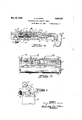
- Figure 1 is a broken elevational view of a machine provided with a table and work rotating device for grinding cylindrical threads which embody features ofvmy inventio
- Figure 2 is a plan view of an indexing table, for grinding threads on flat work pieces, which embodies additional features of my invention
- Figure 3 is an elevational view of the structure shown in Figure 2,
- Figure 4 is a broken side view, partly in section and partly in elevation, 01' the structure shown in Figure 2,
- Figure 5' is a sectional view of the structure shown in Figure 6 taken along the thereof,
- Figure 6 is a broken reduced view, partly in section, of the structure shown in Figure-2,
- Figure 7 is a sectional view of the structure line 1--1 thereof.
- Figure 8 is a plan view of the table shown in Figure 2 with a driving mechanism substituted for the indexing plate thereof,
- Figure 9 is an enlarged broken sectional view of the structure shown in Figure,8, taken along the line 9-9 thereof,
- Figure 10 is a broken sectional view of the structure shown in Figure 8, taken along the line
- Figure 11 is an enlarged sectional view of the structure shown in Figure 8, taken along the line thereof,
- Figure 12 is a sectional view of the structure shown in Figure 11, taken along the line
- Figure 13 is a sectional view of the structure shown in Figure 12, taken along the line
- Figure 14 is a sectional view of the structure shown in Figure 12, taken, along the line
- Figure 15 is an enlarged sectional view of the structure shown in Figure 8, taken along the line
- Figure 16 is a sectional view of the structure shown in Figure 15, taken along the line
- Figure 17 is a view of the structure shown in Figure 12, with the clamping nut for the shaft, shown in section.
- My invention comprises in general a machine 20 having a rotatable machining element 2
- a work carrying mechanism 23 is mounted on the machine 20 for the purpose of moving a work piece, relative to the machining element 2
- the mechanism 23 as comprising a base plate 24 which is mounted for angular movement about a pin 25 relative to a fiat surface 26 of the machine.
- a work supporting table 21 is mounted for longitudinal movement on the plate 24, by races 28 between which a row of ball bearings 29 are provided and retained in predetermined relation to each other by acage 3
- Relative movement is effected between the base plate 24 and the table 21 by a lead screw 32 which is supported on the plate 24 by a collar 33 and supporting bolts 34.
- a nut 35 is screwed on the lead screw 32 and retained in a boss 36 of a web 31 provided on the underside of the table 21 for the purpose of moving the table relative to the lead screw.
- the nut 35 is made of two parts, the inner part 38 being provided with a reduced portion 39 which fits snugly within the boss 36 and which is movable outwardly, frontward thereof.
- is provided frontwardly of the part shown in Figure 4 taken along the line 5-5- 38 and is connected thereto by a pair of pins 42, one end of which is fixed in the part 38, the other end of which is slidable in apertures 43 provided in the part 4
- An arm 44 projects from the part 4
- a flat spring 41 is provided with a pair of arms 48 which span the lead screw 32 and is retained in biased relation with the outer surface of the part 4
- the outermost stud 49 isprovided with a projection 5
- the lead screw is provided with a collar 54 against which a pair of bearings 55 are biased by abifurcated spring 56 which is retained on a projection 51 by a screw 58 in a manner similar to the mounting of the spring 41 on the web 31.
- the bias of the bearings 55 against the shoulder 54 retains-the lead screw 32 in frontwardly position relative to the collar 33 and prevents the screw from moving longitudinally relative to the ,collar, when rotated.
- the collar 33 for supporting the lead screw is mountedby two machine screws 34 and that the nut 35 is retained in fixed relation with the hub 36 by the spring 41, and that the removal of the screw 52 releases the spring 41 from engagement with the nut which is then slidably removable from the hub 36.
- the collar 33 is released from the plate 24 and the screw, the nut and the collar may be removed as a unit from the work carrying mechanism 23 and a new lead screw 32 having a differently pitched thread may be readily substitutedtherefor. In this manner the indexing of the table or the speed of movement thereof relative to the rotation of the work piece may be quickly adjusted.
- having a plurality of notches 62 disposed in predetermined position about its periphery.
- the number and. positioning of the notches vary with the pitch of the lead screw and the pitch of the threads to be cut in the work piece.
- is provided with a tapered central hole which 64 is provided.
- -Work provided with slots 16 for the purpose of permitbe disposed in'angular engages the tapered surface 62 i'rontwardly on the lead screw 32 on the end of which a thread A-differentially threaded cap nut 65, that is to say a cap nut having a pair of threads of different pitch, is first screwed on to the indexing head GI and the nut and plate as a unit are then screwed on to the thread 64 of the lead screw.
- a thread A-differentially threaded cap nut 65 that is to say a cap nut having a pair of threads of different pitch
- the nut 65 is then moved in the opposite or counter-clockwise direction, relative to the head 6
- the'nut 65 is turned in a clockwise direction to force the tapered end 63 longitudinally of the head 6
- An arm 56 is pivoted, by a shaft 61, to the base plate 24 having a pin 68 in the end thereof which projects into the plane through the head M.
- a spring 69 is Wound about the shaft 67, having one end fixed to the arm 66 and the other end abutting against the base plate 24 for the purpose of forcing the arm towards the plate to have the pin 68 thereof engage the outer periphery of the head.
- a cam ll pivoted by the pin 12 to the base plate 24, engages an extension 13 of the arm 66 for actuating the pin 68 outwardly from the periphery of the head 6
- the shaft 12 extends frontwardly of the cam and is provided with a handle 14 as shown in Figure 6 for the purpose of actuating the arm..
- the arm 14 is moved downwardly to cause the pin 68 to disengage a notch 62 of the indexing head, for the purpose of permitting the head 6
- the notches are disposed 180 a distance equal to lead screw 32.
- the tiltable bar arrangement may be employed alone to effeet the very slight difference in pitch.
- the tiltable bar is used in combination with the angular displacement of the lead screw,
- acoverlB which is attached to the rear end of the table at one end and to a roller 19 at its other end for the purpose of being drawn upwardly and over the ball bearings and the races as the table is of the base plate. Pulleys pivotal relation on the base moved frontwardly 8
- the end of the cover .18 attachedthereix causes it to be unwound'from the roll 19 and to be drawn across the upper'surface of the base plate.
- the unwinding of the roll 19 by thetable causes the cord or cable 82 to be wound 83 and when the table 21 is moved rearwardly, the cord is drawn therewith over the pulleys'8l to cause the pulley 83 to be turned in a direction to on the pulley wind up the cover 18-.
- An idling roller 84 is protool in accordance with the pitch of the thread of the lead screw.
- a member 86 is mounted in fixed position on the table and is provided with a yoke 81 on one end and a head 88-on the other end, the latter of which is adjustable relative to the member 86 in a slot 89 whereon it is retained in fixed position by the tightening of a handle 9I on a supporting screw 92.
- a spindle 93 of a well known type is carried by the head 88 and a driving spindle 94 is carried by the yoke 81.
- a centering chuck 95 is provided exteriorly of the-yoke on the spindle 94 for the purpose of securing one end of the work piece in fixed relation to the driving spindle.
- a driving gear 96 is provided in the yoke in slidable engagement with the driving spindle 94.
- a driving head 91 is mounted on the end of the lead screw 32 and is driven through a reversible gear train 90 which is supported on the base plate 24.
- a shaft 99 extends from the gear train 98 and is provided with a plurality of pulleys IOI by means of which the shaft is driven.
- An oppositely disposed plurality of pulleys I02 are mounted in alignment with the pulleys IOI on a shaft I03 on which a gear wheel I04 is mounted in fixed rela-' tion.
- a worm I05 engages the worm wheel I04 and is driven by ashaft I06 of a motor I01, all of which is mounted in fixed relation to the base plate 24.
- a suitable belt I08 is provided to interconnect the pulleys IOI and I02, which is movable into engagement with any one of a plurality of sets thereof for the purpose of changing the speed of rotation of the shaft 99 for driving the gear train 98.
- Thegear train has been shown in sections in Figures 9 and 10, for illustrating the relation of the gears when in driving and in reversing relation.
- the shaft 99 is provided with a worm I09, within the casing III for the gears, and engages a worm wheel II2 for the purpose of rotating it in a clockwise direction.
- a shaft II3, fixed to the worm wheel I I2 is journaled in the bosses I I4 of the gear casing II, and has gears H5 and H6 mounted in fixed relation thereon.
- the gears ,I I5 and H6 are likewise rotated in a clockwise direction.
- Each of the gears II! and I26 are provided on their adjacent'sides with ratchet teeth I21 and I28, respectively, having the ratchet faces there-' tudinal movement.
- a slot I3I is provided in the central body portion of the ratchet member I30, in
- the driving head 91 is rotated in a counterclockwise direction and when the ratchet member I30 engages the ratchet teeth I28 of the gear I26, the driving head 91 is operated in a clockwise direction.
- the handle I3I controls the movement of the work supporting table 21 to have it move in a frontward or a rearward direction.
- the driving head 91 is provided with a gear I36 which meshes with the gear 96 for driving the spindle 94.
- a bifurcated member I31 spans the gear 96 and is attached to the base plate 24.
- the member I 31 retaining the gear 96 in mesh with the driving gear I36 as the spindle 94 moves longitudinally through the gear as the table is moved by the lead screw 32.
- the work is rotated as the table is drawn across the face of the cutting tool, by the driving head 91 which operates the lead screw 32 to advance the table at the same time as it rotates the work piece relative to the cutting tool. It has been pointed out above how the backlash, between the driving head 91 and the table, is eliminated from the lead screw, its driving nut and supporting collar, in order that the table may be moved in either direction and be retained in predetermined relation to the lead screw.
- the driving head is shown enlarged in Figures 11 to 14 inclusive, as comprising a. cylindrical member I40 having a flange I4I on one end and having threads I42 on the other end on which a washer I43 is screwed and retained in fixed spaced relation on the member I40 relative to the flange I4I. Between the flange MI and the washer I43 a second washer I44 is provided, along with the gear I36, both of which are mounted for rotational movement on the outer surface of the cylindrical member I40.
- Two driving pins I 45 are mounted in fixed relation to the gear I36, and extend either side thereof, the portion extending frontwardly of the washer I43 engaging the driving member IZI provided on the end of the shaft H9.
- the other end of the pins I45 extends through spect to the washer.
- the gear I36 is movable relative to the washers I43 and I44 and the flange I 4
- I have provided a pair of threaded holes I53 and I54 in which screws I55 and I56,respective ly are provided.
- a spring I51 - is employed between the screw I56 and the pin ISI for effecting a bias tothe-pin' I5I relative to the slot in order that the adjustment of the screw I55 may readily be made to force the pin I 5
- a sleeve I59 which is slidable on the spindle 94 and which is keyed to the gear 56 by the key I6I'.
- a pair of tapered slots I62 are provided in diametrically opposite'relation in the sleeve I 59, in which a pair of tapered keys I63 are mounted, having tapered key portions I64 which, engage keyways I65 provided longitudinally of the shaft.
- a pair of set screws I66 mounted in a ring I 69 are employed for adjusting the members I63 relative to the tapered slot I62 of the sleeve.
- the keys By having the keys thus adjustable relative to the keyways, they may engage the key-ways I 65 in such manner. that the gear is retained in slidable relation to ,to a cutting tool and which maybe adjusted so as to have the work piece indexed relative to the lead screw in such manner that the resulting thread provided in the work piece is of a different pitch from that of the screw.
- the lead screw is mounted in such manner on my table that it is readily removable for the purpose of changing V the lead screw and therefore the indexing ofthe table.
- a compensating driving head is provided on the endof the lead screw which takes up the play from between the rotation of the work and the longitudinal movement of the table each time the table is reciprocated.
- the compensating means is adjustable so that the amount of play compensated for can be regulated in accordance with the amount of play which may exist between the various machines. 7
Landscapes
- Engineering & Computer Science (AREA)
- Mechanical Engineering (AREA)
- Constituent Portions Of Griding Lathes, Driving, Sensing And Control (AREA)
Description
I Mg 28, 1935.
H. Q. MUNN ADJUSTABLE woax CARRYING TABLE Fnd March 25,1931
5 Sheets-Sheet .1
INVENTOR ficnrg Qyz'ntllfi Mann.
'ITORNEYS.
May 28, 1935. H. Q. MUNN ADJUSTABLE WORK CARRYING TABLE Filed March 25, 1931 5 Sh etS -Sheet 1 NVENTOP. 7/ f/cnry flair/2i M TTORNEYS,
May 28, 1935. H. Q. MUNN 2,003,263
ADJUSTABLQ WORK CARRYING TABLE Filed March 25 1931 5 Sheets-Sheet 3 67 r INVE NT0R 34 Hcnry (P00778771 M07771.
ATTORNEYS.
MayZS, 1935. H. Q. MUNN ADJUSTABLE'WORK cmnyme TABLE Filed March 25, 1 1 5 Sheets-Sheet 4 INVENTOR Henry QI/Lflhih M02727.
( BY /JMHA @qzz m I I TTORNEYS.
May 28, 1935.
H. Q, MUNN ADJUSTABLE WORK CARRYING TABLE 5 Sheets-Sheet 5 Filed March 25, 1931 INVENTOR 64 Henry alrintin Mun/z NEY amount meme May 2c, 1935 UNITED STATES PATENT OFFICE Henry Quintin Munn, Walkerville, Ontario, Canada, assignor to Michigan Tool Company, a corporation of Michigan Application March. 25,
5 Claims.
My invention relates to precision indexing machines and particularly to a work carrying table which is provided with interchangeable driving means whereby it may be moved a predetermined at intervals or caused to travel at a predetermined speed relative to a cutting memher, the amount of movement being variable and adjustable.
Difiiculty has been experienced in the past, when employing a lead screw for driving a work carrying table, in moving the table in opposite directions in such manner as to retain all points of the work piece in predetermined relation to a cutting element during both directions of movement. The driving means for the table and the support for the lead screw had lost motion or back lash therebetween which prevented the positioning of the table relative to the cutting element when the direction of movement of the table was changed. Accordingly when a thread was cuton a member, it has been the practice to machine the member in one direction only and the reciprocation of the machine to its original position was efiected without a machining operation.
In practicing my invention, I eliminate the back lash from between the driving member and the table .in order that it may be operated in either direction .and be retained in predetermined relation to a cutting element in either direction of movement. When the work piece is to be rotated relative to the movement of the table I provide a compensating member between the. driving member for the lead screw and that for effecting the rotation of the work piece, which prevents the movement of the table until the play in the work rotating mechanism is taken up. In this construction, the driving of the table and the work piece will be eflected in such manner that the work piece and the table are always relative to each other and the cutting tool, in either direction of motion of the table.
Accordingly one object of my invention is to provide mechanism for a table which supports a work piece, that shall efiect the movement of the table and the rotation of the work piece in such j manner that the movements are relative to each other and to a cutting tool, in either direction of movement of the table.
Another object of my invention, is to provide a compensating device in conjunction with the work supporting table in such manner as to produce uniform rectilinear relation to uniform rotational motion of the work in one case; or to produce equal movements of motion of the table in 1931, Serial No. 525,221 (or. 51 -95) the table for integral turns of the lead screw in another case.
A further object of my invention is to provide a supporting member for a lead screw for driving a work table longitudinally of a cutting tool, which shall be capable of supporting interchangeable lead screws of greater or lesser pitch for regulating the travel of the tablerelative to the cutting tool.
A further object of my invention is to provide 10 an indexing head for the lead screw of the table of the above described type, which shall be effective for moving the table a predetermined amount at intervals during the machining of the work piece.
A still further object of my invention is to provide a table of the above described type with an adjustable work support which shall permit the lead screw to be positioned in angular relation to the line of motion imparted to the work and table as a whole, during machining of a thread on a plane surface, in such manner that the intervals between consecutive threads shall be equal to one another, but less by a predetermined amount than the pitch-or multiple of the pitch-of the lead screw; the intervals being effected by an integral number of turns of the lead screw.
A still further object of my invention is to provide a work table of the above described indexing head may be interchanged for a continuous driving'mechanism which is provided with back lash removing and compensating means referred to hereinabove.
Numerous other objects and features of novelty of lny invention will be either specifically pointed out or will become apparent when referring, for a better understanding of my invention, to the following descriptions in conjunction with the accompanying drawings, 40 wherein:
Figure 1 is a broken elevational view of a machine provided with a table and work rotating device for grinding cylindrical threads which embody features ofvmy inventio Figure 2 is a plan view of an indexing table, for grinding threads on flat work pieces, which embodies additional features of my invention,
Figure 3 is an elevational view of the structure shown in Figure 2,
Figure 4 is a broken side view, partly in section and partly in elevation, 01' the structure shown in Figure 2,
Figure 5' is a sectional view of the structure shown in Figure 6 taken along the thereof,
Figure 6 is a broken reduced view, partly in section, of the structure shown in Figure-2,
Figure 7 is a sectional view of the structure line 1--1 thereof,
Figure 8 is a plan view of the table shown in Figure 2 with a driving mechanism substituted for the indexing plate thereof,
Figure 9 is an enlarged broken sectional view of the structure shown in Figure,8, taken along the line 9-9 thereof,
Figure 10 is a broken sectional view of the structure shown in Figure 8, taken along the line |0-|6 thereof,
Figure 11 is an enlarged sectional view of the structure shown in Figure 8, taken along the line thereof,
Figure 12 is a sectional view of the structure shown in Figure 11, taken along the line |2-|2 thereof,
Figure 13 is a sectional view of the structure shown in Figure 12, taken along the line |3|3 thereof,
Figure 14 is a sectional view of the structure shown in Figure 12, taken, along the line |4|4 thereof,
Figure 15 is an enlarged sectional view of the structure shown in Figure 8, taken along the line |5-|5 thereof,
Figure 16 is a sectional view of the structure shown inFigure 15, taken along the line |6|6 thereof, and
Figure 17 is a view of the structure shown in Figure 12, with the clamping nut for the shaft, shown in section.
My invention comprises in general a machine 20 having a rotatable machining element 2|, herein shown as an abrading member, which is driven by suitable driving means 22 which may be regulated to rotate the element 2| at a variable number of speeds. A work carrying mechanism 23 is mounted on the machine 20 for the purpose of moving a work piece, relative to the machining element 2|, a predetermined amount each time the work supporting table is indexed or of moving the work piece laterally across the edge of the elements 2|, to have the element engage the work piece at spaced continuous points thereof in the nature of a helix or a screw thread.
Referring to Figures 4 to 7 inclusive, I have illustrated the mechanism 23 as comprising a base plate 24 which is mounted for angular movement about a pin 25 relative to a fiat surface 26 of the machine. A work supporting table 21 is mounted for longitudinal movement on the plate 24, by races 28 between which a row of ball bearings 29 are provided and retained in predetermined relation to each other by acage 3|. Relative movement is effected between the base plate 24 and the table 21 by a lead screw 32 which is supported on the plate 24 by a collar 33 and supporting bolts 34. A nut 35 is screwed on the lead screw 32 and retained in a boss 36 of a web 31 provided on the underside of the table 21 for the purpose of moving the table relative to the lead screw.
The nut 35 is made of two parts, the inner part 38 being provided with a reduced portion 39 which fits snugly within the boss 36 and which is movable outwardly, frontward thereof. A sec- 0nd part 4| is provided frontwardly of the part shown in Figure 4 taken along the line 5-5- 38 and is connected thereto by a pair of pins 42, one end of which is fixed in the part 38, the other end of which is slidable in apertures 43 provided in the part 4|. An arm 44 projects from the part 4| and extends laterally of the lead screw 32 and rests upon a sloping bar 45 against which it is retained by a spring 46 for a purpose which will be described more fully hereinafter.
A flat spring 41 is provided with a pair of arms 48 which span the lead screw 32 and is retained in biased relation with the outer surface of the part 4| of the nut, by the studs 49 which are mounted on the web 31' of the table. The outermost stud 49 isprovided with a projection 5| which extends through the outer end of the spring 41, while the inner stud -49 is provided with a screw 52 for retaining the spring 41 on the studs.
The bias effected by the arms 48, forces the threads of the outer part 4| of the nut 35, against the outer surface of the thread, while the inner surface ofthe threads of the part 38 is drawn against the inner surface of the threads of the screw. In this manner the threads between the two parts of the nut and that on the lead screw are always retained in predetermined biased position to each other during either movement of the screw 32 and no back lash will be present between the lead screw and the driving means for I,
the table.
To eliminate the back lash from the supporting end of the lead screw 32, the lead screw is provided with a collar 54 against which a pair of bearings 55 are biased by abifurcated spring 56 which is retained on a projection 51 by a screw 58 in a manner similar to the mounting of the spring 41 on the web 31. The bias of the bearings 55 against the shoulder 54, retains-the lead screw 32 in frontwardly position relative to the collar 33 and prevents the screw from moving longitudinally relative to the ,collar, when rotated. By eliminating the back lash from both they supporting and the driving means associated with the lead screw, the lead screw may be reversed at any point in its travel and still have the work retained in predetermined relation to the threads of the screw.
It will be noted that the collar 33 for supporting the lead screw is mountedby two machine screws 34 and that the nut 35 is retained in fixed relation with the hub 36 by the spring 41, and that the removal of the screw 52 releases the spring 41 from engagement with the nut which is then slidably removable from the hub 36. When the two screws 34 are removed, the collar 33 is released from the plate 24 and the screw, the nut and the collar may be removed as a unit from the work carrying mechanism 23 and a new lead screw 32 having a differently pitched thread may be readily substitutedtherefor. In this manner the indexing of the table or the speed of movement thereof relative to the rotation of the work piece may be quickly adjusted.
For indexing the table 21 relative to the plate 24, I have provided an indexing head 6| having a plurality of notches 62 disposed in predetermined position about its periphery. The number and. positioning of the notches vary with the pitch of the lead screw and the pitch of the threads to be cut in the work piece. In Figure 3, I have shown thenotches to be two in number which effect the indexing of the table 21 at one half of the pitch of the lead screw 32. The head 6| is provided with a tapered central hole which 64 is provided.
to hereinabove. -Work provided with slots 16 for the purpose of permitbe disposed in'angular engages the tapered surface 62 i'rontwardly on the lead screw 32 on the end of which a thread A-differentially threaded cap nut 65, that is to say a cap nut having a pair of threads of different pitch, is first screwed on to the indexing head GI and the nut and plate as a unit are then screwed on to the thread 64 of the lead screw. After the head 6| rests against the tapered shoulder 63 of the screw, the nut 65 is then moved in the opposite or counter-clockwise direction, relative to the head 6|, which, due to the difierential relation of the threads, causes the tapered portion 63 to be drawn tightly within the central tapered aperture of the head 6i and the two threads of the nut to be in locking relation to the thread of the lead screw 32 and that of the.indexing head 5!. To release the head from the screw, the'nut 65 is turned in a clockwise direction to force the tapered end 63 longitudinally of the head 6| to thereby loosen the head on the screw andthe head 65 is screwed as a unit with the nut 65 ofi of the thread 6: 3. i
An arm 56 is pivoted, by a shaft 61, to the base plate 24 having a pin 68 in the end thereof which projects into the plane through the head M. A spring 69 is Wound about the shaft 67, having one end fixed to the arm 66 and the other end abutting against the base plate 24 for the purpose of forcing the arm towards the plate to have the pin 68 thereof engage the outer periphery of the head. A cam ll, pivoted by the pin 12 to the base plate 24, engages an extension 13 of the arm 66 for actuating the pin 68 outwardly from the periphery of the head 6|. The shaft 12 extends frontwardly of the cam and is provided with a handle 14 as shown in Figure 6 for the purpose of actuating the arm..
After a. out has been taken across the work piece the arm 14 is moved downwardly to cause the pin 68 to disengage a notch 62 of the indexing head, for the purpose of permitting the head 6| to be turned to advance the work piece a. predetermined amount to a point where the pin 68 engages the next succeeding notch. In the construction herein shown, the notches are disposed 180 a distance equal to lead screw 32. I
When the spacing of the one half- 01' the pitch of the serrations of the 'work piece is to be slightly changed relative to the lead angle of the screw 32, the screw is oil.- set angularly to the normal position of the work piece which is retained relative to the cutter, by moving the base plate 24 relative to the surface 26 of the machine about the pin referred clamping members 15 are ting the members 15 to relation on the table 21, when the supporting bolts are moved in the slots in the table 21 so as to support the work piece to have the thread thereof In this construction, a distance advanced by the nut 35 along the lead screw 32, will be equal to the distance in which the work-has been advanced relative to the cutting element multiplied by the cosine of the angle which the lead screw 32 has been set off relative to its normal position. In this manner, threads of different pitch from that of the thread of the lead screw may be machined by setting off the work supporting table and lead screw angularly relative effected by pitches after the lead screw 32 has degrees apart which advances the table,
parallel to the direction of movement of the cutting element thereacross.
to the normal retained position or the work piece, a predetermined amount computable by the above mentioned relation.
To effect a further adjustment for varying the pitch between the threads-of the work piece relative to the thread of the lead screw besides that offsetting the relative to the direction of'movement of the work piece, I provide the sloping bar 45 and the arm 44 extending from the nut 35, for the purpose of advancing the nut on the thread as the table moves relative'to the base plate 24.. It is very iead screw angulafly apparent that if the nut is advanced on the thread at the same time the thread is turned to advance the nut thereon, is the sum of the two. advancements which are cumulative- The bar may be so constructed as to be tiltable effect throughout the length of the screw which will therebfprovidea very fine adjustment for relatingthe serrations out, to the screw thread.
When only a very slight change is to be efthe resulting motion to the nut through a small angle to vary itstested between the thread to be cut in the work Y piece and the tread of the lead screw,- the tiltable bar arrangement may be employed alone to effeet the very slight difference in pitch. When a greater change is to be effected pitches, the tiltable bar is used in combination with the angular displacement of the lead screw,
to effect a very fine adjustment between the two been adjusted.
When my table'mechanism is constructed to cut threads in fiat work pieces, having pitches which may be greater or less than the pitch of a particular lead screw, ,1 construct the lead screw to index the standard pitch, when the lead screw is disposed medially of itsmaximum angle of dis.- placement relative to the direction of motion of the workpiece. In this construction when a pitch greater than normal is desired, the angular displacement of the lead screw is decreased and 1 ii the pitchis tobe less than .the normal pitch-,
the angle of displacement is increased.
To protect the ball bearings 29 and the surface of the race- 28, from the cutting and abrading particles,which may fall thereon during the cutting operation, I' have provided acoverlB which is attached to the rear end of the table at one end and to a roller 19 at its other end for the purpose of being drawn upwardly and over the ball bearings and the races as the table is of the base plate. Pulleys pivotal relation on the base moved frontwardly 8| are mounted in between the plate 24 over which a cord or cable 82 extends,"
one end of which is attached in fixed relationto the table, while the other end is wound about the pulley 82 provided on the end of the roller I9.
As the table 2'! is moved forwardly on the base plate 24, the end of the cover .18 attachedthereix) causes it to be unwound'from the roll 19 and to be drawn across the upper'surface of the base plate. The unwinding of the roll 19 by thetable causes the cord or cable 82 to be wound 83 and when the table 21 is moved rearwardly, the cord is drawn therewith over the pulleys'8l to cause the pulley 83 to be turned in a direction to on the pulley wind up the cover 18-. An idling roller 84 is protool in accordance with the pitch of the thread of the lead screw. A member 86 is mounted in fixed position on the table and is provided with a yoke 81 on one end and a head 88-on the other end, the latter of which is adjustable relative to the member 86 in a slot 89 whereon it is retained in fixed position by the tightening of a handle 9I on a supporting screw 92.
A spindle 93 of a well known type is carried by the head 88 and a driving spindle 94 is carried by the yoke 81. A centering chuck 95 is provided exteriorly of the-yoke on the spindle 94 for the purpose of securing one end of the work piece in fixed relation to the driving spindle. A driving gear 96 is provided in the yoke in slidable engagement with the driving spindle 94.
A driving head 91 is mounted on the end of the lead screw 32 and is driven through a reversible gear train 90 which is supported on the base plate 24. A shaft 99 extends from the gear train 98 and is provided with a plurality of pulleys IOI by means of which the shaft is driven. An oppositely disposed plurality of pulleys I02 are mounted in alignment with the pulleys IOI on a shaft I03 on which a gear wheel I04 is mounted in fixed rela-' tion. A worm I05 engages the worm wheel I04 and is driven by ashaft I06 of a motor I01, all of which is mounted in fixed relation to the base plate 24. A suitable belt I08 is provided to interconnect the pulleys IOI and I02, which is movable into engagement with any one of a plurality of sets thereof for the purpose of changing the speed of rotation of the shaft 99 for driving the gear train 98.
Thegear train has been shown in sections in Figures 9 and 10, for illustrating the relation of the gears when in driving and in reversing relation. The shaft 99 is provided with a worm I09, within the casing III for the gears, and engages a worm wheel II2 for the purpose of rotating it in a clockwise direction. A shaft II3, fixed to the worm wheel I I2, is journaled in the bosses I I4 of the gear casing II, and has gears H5 and H6 mounted in fixed relation thereon. When the worm wheel I I2 is driven in a clockwise direction I by the worm I09, the gears ,I I5 and H6 are likewise rotated in a clockwise direction. Referring to Figure 9, which is'a section through the casing I I I frontwardly of the gear I I6, the gear is shown as being in mesh with a gear III which is rotatably mounted on a shaft H9. The shaft is provided with a driving member I2I exteriorly of the housing I II for engaging the driving head 91.
In Figure 10, I have shown a section through the casing I I I frontwardly of the gear I I5, wherein the gear H5 is shown-in mesh with an idling gear I23 mounted on a stub shaft I24 which is supported on the side of the casing III by the nut I25. The idling gear I23 meshes with a gear I26 which is mounted on the shaft H9 in such manner as to be rotated relative thereto. In this construction, when the worm I09 is revolved, the worm wheel H2 is rotated, which in turn rotates the gears H5 and H6, in a clockwise direction. The gear I I6 rotating the gear I I1 relative to the shaft I I9 in a counterclockwise direction and the gear I I 5, operating through the gear I23, actuates the gear I26 in a clockwise direction.
Each of the gears II! and I26 are provided on their adjacent'sides with ratchet teeth I21 and I28, respectively, having the ratchet faces there-' tudinal movement. A slot I3I is provided in the central body portion of the ratchet member I30, in
' which a camming end I32 of a shaft I33 registers to be actuated by a handle I34.
When the handle is moved downwardly. the cam I32, operating in the slot I3I, forces the ratchet member I30 into engagement with the ratchet teeth I21 of the gear II1. When the handle is moved in an upwardly direction, the ratchet member I30 is released from the ratchet teeth I21 and is moved into engagement with the ratchet teeth I29 of the gear I26. The medial position of the handle disconnects the gears entirely from the driving member I2I. The engagement of the teeth I21 and I28 with the ratchet member I30 effects a driving connection between the gears III or I28,with the driving shaft 99. When the ratchet member I30 is connected to the teeth I21 of the gear II! the driving head 91 is rotated in a counterclockwise direction and when the ratchet member I30 engages the ratchet teeth I28 of the gear I26, the driving head 91 is operated in a clockwise direction. In this manner the handle I3I controls the movement of the work supporting table 21 to have it move in a frontward or a rearward direction.
The driving head 91 is provided with a gear I36 which meshes with the gear 96 for driving the spindle 94. A bifurcated member I31 spans the gear 96 and is attached to the base plate 24. The member I 31 retaining the gear 96 in mesh with the driving gear I36 as the spindle 94 moves longitudinally through the gear as the table is moved by the lead screw 32. In this manner, the work is rotated as the table is drawn across the face of the cutting tool, by the driving head 91 which operates the lead screw 32 to advance the table at the same time as it rotates the work piece relative to the cutting tool. It has been pointed out above how the backlash, between the driving head 91 and the table, is eliminated from the lead screw, its driving nut and supporting collar, in order that the table may be moved in either direction and be retained in predetermined relation to the lead screw.
It will be very apparent that a similar back lash eliminating or compensating device is required between the driving head 91 and the spindle 94 in order to take up or eliminate any lost motion which may be present between the gear teeth, and the connection of the gear 96 on the spindle 94. In my present construction, I have provided a compensating arrangement for eliminating the effectsof any lost motion or back lash in the rotating portion of my machine, which is incorporated in the driving head 91 and which will now be described in detail.
The driving head is shown enlarged in Figures 11 to 14 inclusive, as comprising a. cylindrical member I40 having a flange I4I on one end and having threads I42 on the other end on which a washer I43 is screwed and retained in fixed spaced relation on the member I40 relative to the flange I4I. Between the flange MI and the washer I43 a second washer I44 is provided, along with the gear I36, both of which are mounted for rotational movement on the outer surface of the cylindrical member I40. Two driving pins I 45 are mounted in fixed relation to the gear I36, and extend either side thereof, the portion extending frontwardly of the washer I43 engaging the driving member IZI provided on the end of the shaft H9.
The other end of the pins I45 extends through spect to the washer.
in the washer I44 and the flange I 4I for the pur- 5 pose of permitting the movement of the inner end of the pin I45 therein. The sides ofthe pin are flattened as at I41 for the purpose of engaging the flat surfaces I48 provided in the ends'of the slots I46 of the washer I44 ar' d the flange I4I.
In this construction it will be noted that the gear I36 is movable relative to the washers I43 and I44 and the flange I 4| an amount equal to the length of the slot I46. It will thus be seen that when the driving member I 2I is first rotated the motion is transferred to the pins I45 to rotate the gear I36 before the flat surfaces I41 of the pins engage the flat surfaces I48 of the slots I 46 to cause the rotation of the cylindrical member I40. Since the cylindrical member I46 is attached, by a threaded flanged member I49 in fixed relation on the end of the shaft 32, by thedifferential nut 64, the shaft will not be rotated until the gear has been moved a predetermined amount.
/ In a similar manner, after the table 27 has been moved to its rearward-most position, the reversing of the gear train 98 causes the gear I36'to be moved backward until the pins I45 engage the opposite end of the slot I 46 before the shaft 32 is rotated therewith. In this construction any play in the gear teeth or between the gear 96 and the spindles 94 will be taken up by the initial L movement of the gear I36 before the shaft 32 is driven.
In order to regulate the amount of movement of the gear I36 relative to the movement of the shaft 32, I have provided a pin I5I which is screwed in the plate I44 and extends within a "'slot I 52 in the flange I4I, to regulate the angular movement of the washer I44 relative to the flange I4 I. When the flanges are thus moved relative to each other the slots I46 therein are also moved to decrease the relative opening therebetweenin which the pins I45 are movable. In this manner the plates may be rotated a sufficient amount to have the opposite sides of the respective-slots tightly clamp the pins I45 relative to the plates and therefore to the cylindrical portion I46 and the driving of the gear I36 and the shaft 32 will then be direct.
For the p se of adjustment, I have provided a pair of threaded holes I53 and I54 in which screws I55 and I56,respective ly are provided. A spring I51 -is employed between the screw I56 and the pin ISI for effecting a bias tothe-pin' I5I relative to the slot in order that the adjustment of the screw I55 may readily be made to force the pin I 5| against the spring. By this means, the play existing between the lead screw 32 and the work piece may be compensated for, to have the relative play taken up between the rotation of the work piece and the longitudinal movement of the table, each time the table is F reciprocated.
It is to be understood that in case the play should appear to be greater between the connection to the lead screw 32 than that to the work .piece, that the mounting ,of the pins I45 may be reversed, that is to say that the pins may be fixed relative to the cylindrical member II to operate in slots provided in the gear I36, in
'which construction the lead screw 32 will be -moved to take up the relative play thereof before the gear I36 is rotated.
To eliminate the play from between'the gear 96 and the spindle 94, I have provided a sleeve I59 which is slidable on the spindle 94 and which is keyed to the gear 56 by the key I6I'. A pair of tapered slots I62 are provided in diametrically opposite'relation in the sleeve I 59, in which a pair of tapered keys I63 are mounted, having tapered key portions I64 which, engage keyways I65 provided longitudinally of the shaft. A pair of set screws I66 mounted in a ring I 69 are employed for adjusting the members I63 relative to the tapered slot I62 of the sleeve. By having the keys thus adjustable relative to the keyways, they may engage the key-ways I 65 in such manner. that the gear is retained in slidable relation to ,to a cutting tool and which maybe adjusted so as to have the work piece indexed relative to the lead screw in such manner that the resulting thread provided in the work piece is of a different pitch from that of the screw. The lead screw is mounted in such manner on my table that it is readily removable for the purpose of changing V the lead screw and therefore the indexing ofthe table. By providing means for retaining the lead screw in predetermined relation to the driving nut and the supporting collar, the back lash,- heretofore present between the base plate and the table is entirely removed. I have provided a driving mechanism for the table and work piece which may be attached to the lead screw in fixed relation with the base plate when the inde g head thereof has been removed. A compensating driving head is provided on the endof the lead screw which takes up the play from between the rotation of the work and the longitudinal movement of the table each time the table is reciprocated. The compensating means is adjustable so that the amount of play compensated for can be regulated in accordance with the amount of play which may exist between the various machines. 7
I'employ a differentially threaded nut for the the driving tapered end in firm relation the nut relative to the head. By tm'ning' the screw in a clockwise direction relative to the head.
the head is forced away from the tapered end of the lead screw. v
While I-have described and illustrated but a single embodiment of my invention, it will be apparant to those skilled in the art that various changes, omissions, additions and substitutions may be made therein without departing from the spirit and scope of my invention, as set forth in the accompanying claims.
I claim as my invention:
1. The method of v ying the indexing of a work piece relative to the angle of lead of an indexing screw which includes the angular disposition of the screw relative to the normal retained pomtion of the work piece.
2. The method of varying the indexing of a work piece relative to the angle of lead ofan indexing screw which includes, the angular disposition of the screw relative to the normal retained position of the work piece, the variation effected occurring as the cosine of the angle so set off.
3. The method of varying the indexing of a work piece relative to the angle of lead of an indexing screw which includes, the angular disposition of the screw relative to the normal retained position of the work piece, the variation effected occurring as the cosine of the angle so set off, and progressively varying the screw engaging means during its movement for effecting a minute adjustment of the indexing.
4. The method of varying the indexing of a work piece relative to the angle of lead of an indexing screw which includes, the angular disposition of the screw relative to the normal retained position of the work piece, and progressively varying the screw engaging means during its movement for efiecting a minute adjustment of the indexing.
5. The combination with a base plate for supporting a lead screw and a driving element for actuating a work supporting table, of an indexing means for said screw for regulating the movement of the table, means for mounting said base plate on a machine normal to a cutting element for angular adjustment relative thereto, means or supporting a work piece on said table relative to the angle adjusted, and a sloping bar associated with said driven element of said screw for efiecting a minute adjustment of the indexing of the work piece.
HENRY QUINTIN MUNN.
Priority Applications (1)
| Application Number | Priority Date | Filing Date | Title |
|---|---|---|---|
| US525221A US2003263A (en) | 1931-03-25 | 1931-03-25 | Adjustable work carrying table |
Applications Claiming Priority (1)
| Application Number | Priority Date | Filing Date | Title |
|---|---|---|---|
| US525221A US2003263A (en) | 1931-03-25 | 1931-03-25 | Adjustable work carrying table |
Publications (1)
| Publication Number | Publication Date |
|---|---|
| US2003263A true US2003263A (en) | 1935-05-28 |
Family
ID=24092405
Family Applications (1)
| Application Number | Title | Priority Date | Filing Date |
|---|---|---|---|
| US525221A Expired - Lifetime US2003263A (en) | 1931-03-25 | 1931-03-25 | Adjustable work carrying table |
Country Status (1)
| Country | Link |
|---|---|
| US (1) | US2003263A (en) |
-
1931
- 1931-03-25 US US525221A patent/US2003263A/en not_active Expired - Lifetime
Similar Documents
| Publication | Publication Date | Title |
|---|---|---|
| US2003263A (en) | Adjustable work carrying table | |
| US1402473A (en) | Machine for grinding taps | |
| US2187062A (en) | Gear grinding machine | |
| US2468478A (en) | Machine tool | |
| US1958105A (en) | Thread grinding machine | |
| US2399621A (en) | Device for automatic lathes | |
| US2445194A (en) | Grinding machine | |
| US2335468A (en) | Work turning device for machine tools | |
| US1660468A (en) | Thread-grinding machine | |
| US2079785A (en) | Hob grinding machine | |
| US2101183A (en) | Arrangement for resetting hobs | |
| US1980444A (en) | Method and means of producing hobs | |
| US2062699A (en) | Burnishing apparatus | |
| US2401561A (en) | Machine for grinding helical gears and other conjugate helicoidal members | |
| US2663292A (en) | Device for truing the grinding wheels of grinding machines | |
| US2368342A (en) | Tool grinding machine | |
| US606837A (en) | gibson | |
| US3875846A (en) | Device for chamfering the end faces of the teeth of toothed members | |
| US1624868A (en) | Metal-working machine | |
| US2425015A (en) | Grid winding machine | |
| US1150535A (en) | Gear-grinding machine. | |
| US1832507A (en) | Machine for profiling gear teeth | |
| GB325520A (en) | Improvements in means for producing worms or cylindrical cams | |
| US1999320A (en) | Centerless grinder | |
| US1870325A (en) | Means for producing worms or cylindrical cams |