US20030197896A1 - Method and apparatus for interactively scanning images into a logical structure - Google Patents
Method and apparatus for interactively scanning images into a logical structure Download PDFInfo
- Publication number
- US20030197896A1 US20030197896A1 US10/393,292 US39329203A US2003197896A1 US 20030197896 A1 US20030197896 A1 US 20030197896A1 US 39329203 A US39329203 A US 39329203A US 2003197896 A1 US2003197896 A1 US 2003197896A1
- Authority
- US
- United States
- Prior art keywords
- documents
- logical entities
- logical
- images
- scanned images
- Prior art date
- Legal status (The legal status is an assumption and is not a legal conclusion. Google has not performed a legal analysis and makes no representation as to the accuracy of the status listed.)
- Granted
Links
Images


Classifications
-
- H—ELECTRICITY
- H04—ELECTRIC COMMUNICATION TECHNIQUE
- H04N—PICTORIAL COMMUNICATION, e.g. TELEVISION
- H04N1/00—Scanning, transmission or reproduction of documents or the like, e.g. facsimile transmission; Details thereof
- H04N1/0035—User-machine interface; Control console
- H04N1/00405—Output means
- H04N1/00408—Display of information to the user, e.g. menus
- H04N1/0044—Display of information to the user, e.g. menus for image preview or review, e.g. to help the user position a sheet
- H04N1/00442—Simultaneous viewing of a plurality of images, e.g. using a mosaic display arrangement of thumbnails
- H04N1/00453—Simultaneous viewing of a plurality of images, e.g. using a mosaic display arrangement of thumbnails arranged in a two dimensional array
-
- G—PHYSICS
- G06—COMPUTING OR CALCULATING; COUNTING
- G06F—ELECTRIC DIGITAL DATA PROCESSING
- G06F16/00—Information retrieval; Database structures therefor; File system structures therefor
- G06F16/50—Information retrieval; Database structures therefor; File system structures therefor of still image data
- G06F16/51—Indexing; Data structures therefor; Storage structures
-
- G—PHYSICS
- G06—COMPUTING OR CALCULATING; COUNTING
- G06F—ELECTRIC DIGITAL DATA PROCESSING
- G06F16/00—Information retrieval; Database structures therefor; File system structures therefor
- G06F16/50—Information retrieval; Database structures therefor; File system structures therefor of still image data
- G06F16/54—Browsing; Visualisation therefor
-
- H—ELECTRICITY
- H04—ELECTRIC COMMUNICATION TECHNIQUE
- H04N—PICTORIAL COMMUNICATION, e.g. TELEVISION
- H04N1/00—Scanning, transmission or reproduction of documents or the like, e.g. facsimile transmission; Details thereof
- H04N1/0035—User-machine interface; Control console
-
- H—ELECTRICITY
- H04—ELECTRIC COMMUNICATION TECHNIQUE
- H04N—PICTORIAL COMMUNICATION, e.g. TELEVISION
- H04N1/00—Scanning, transmission or reproduction of documents or the like, e.g. facsimile transmission; Details thereof
- H04N1/32—Circuits or arrangements for control or supervision between transmitter and receiver or between image input and image output device, e.g. between a still-image camera and its memory or between a still-image camera and a printer device
- H04N1/32101—Display, printing, storage or transmission of additional information, e.g. ID code, date and time or title
- H04N1/32106—Display, printing, storage or transmission of additional information, e.g. ID code, date and time or title separate from the image data, e.g. in a different computer file
- H04N1/32112—Display, printing, storage or transmission of additional information, e.g. ID code, date and time or title separate from the image data, e.g. in a different computer file in a separate computer file, document page or paper sheet, e.g. a fax cover sheet
-
- H—ELECTRICITY
- H04—ELECTRIC COMMUNICATION TECHNIQUE
- H04N—PICTORIAL COMMUNICATION, e.g. TELEVISION
- H04N2201/00—Indexing scheme relating to scanning, transmission or reproduction of documents or the like, and to details thereof
- H04N2201/32—Circuits or arrangements for control or supervision between transmitter and receiver or between image input and image output device, e.g. between a still-image camera and its memory or between a still-image camera and a printer device
- H04N2201/3201—Display, printing, storage or transmission of additional information, e.g. ID code, date and time or title
- H04N2201/3225—Display, printing, storage or transmission of additional information, e.g. ID code, date and time or title of data relating to an image, a page or a document
- H04N2201/3226—Display, printing, storage or transmission of additional information, e.g. ID code, date and time or title of data relating to an image, a page or a document of identification information or the like, e.g. ID code, index, title, part of an image, reduced-size image
-
- H—ELECTRICITY
- H04—ELECTRIC COMMUNICATION TECHNIQUE
- H04N—PICTORIAL COMMUNICATION, e.g. TELEVISION
- H04N2201/00—Indexing scheme relating to scanning, transmission or reproduction of documents or the like, and to details thereof
- H04N2201/32—Circuits or arrangements for control or supervision between transmitter and receiver or between image input and image output device, e.g. between a still-image camera and its memory or between a still-image camera and a printer device
- H04N2201/3201—Display, printing, storage or transmission of additional information, e.g. ID code, date and time or title
- H04N2201/3225—Display, printing, storage or transmission of additional information, e.g. ID code, date and time or title of data relating to an image, a page or a document
- H04N2201/3247—Data linking a set of images to one another, e.g. sequence, burst or continuous capture mode
-
- H—ELECTRICITY
- H04—ELECTRIC COMMUNICATION TECHNIQUE
- H04N—PICTORIAL COMMUNICATION, e.g. TELEVISION
- H04N2201/00—Indexing scheme relating to scanning, transmission or reproduction of documents or the like, and to details thereof
- H04N2201/32—Circuits or arrangements for control or supervision between transmitter and receiver or between image input and image output device, e.g. between a still-image camera and its memory or between a still-image camera and a printer device
- H04N2201/3201—Display, printing, storage or transmission of additional information, e.g. ID code, date and time or title
- H04N2201/3271—Printing or stamping
Definitions
- the present invention relates to the field of scanning documents into images and storing the images as electronic files. More specifically, the present invention relates to the intelligent and interactive control of such functions and the storing of the scanned images into a logical structure.
- the documents When converting business or scientific documents from paper to electronic images, the documents often have an organization format where groups of the documents are physically separated by some type of barrier, such as boxes, staples, clips, binders, rubber bands, and even by document type (e.g., figures and text).
- some type of barrier such as boxes, staples, clips, binders, rubber bands, and even by document type (e.g., figures and text).
- document type e.g., figures and text
- existing scan capture programs provide the ability to do so only into fixed, flat structures, if at all. For example, using currently available scanner products, scanned images can be associated with one another by being placed into “documents” and/or a “batch”. These structures are extremely limited and their implementations are typically cumbersome.
- slipsheets include barcodes or other symbols that the scanner can recognize in order to delimit groups of images and associate them with a structure of some sort.
- the physical handling of such slipsheets is complicated and cumbersome and attempting to allow many different logical structures to be indicated using such a method is especially difficult and prone to error.
- Such a solution is also quite slow and errors are impossible to detect or rectify until the documents have already been stored and/or printed out erroneously.
- the present invention provides a method and system for scanning a set of documents.
- the set of documents to be scanned are in an organizational format wherein groups of the documents are separated by barriers.
- the method and system include displaying a set of logical entities that represent the barriers to an operator of a scanner; and associating scanned images of the documents with at least one of the logical entities.
- the method and system further include using the association of the logical entities to store and print the scanned images, such that the organizational format of the documents is retained.
- the present invention provides an interactive and easy-to-use scanning application that retains designated relationships between documents during scanning, and that stores the scanned images along with those designated relationships.
- the scanner application also enables an operator to optionally print the images in such a way that the document relationships are apparent without reference to the original documents.
- the scanner application allows the operator to view the operator-defined logical relationships among the documents in an interactive fashion so that errors can be detected and rectified before the documents are finally scanned and stored.
- FIG. 1 is a block diagram of a scanning system in accordance with a preferred embodiment of the present invention.
- FIG. 2 is a flow chart illustrating the process the scanner application performs to enable an operator to interactively scan a set of documents into a logical structure that represents the organizational format of those documents.
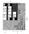
- FIG. 3 is a diagram of one preferred embodiment of the user interface screen displayed by the scanner application.
- FIG. 4 is a diagram of a second preferred embodiment of the user interface screen displayed by the scanner application.
- the present invention relates to an improved method for the scanning and storing of documents.
- the following description is presented to enable one of ordinary skill in the art to make and use the invention and is provided in the context of a patent application and its requirements.
- Various modifications to the preferred embodiments and the generic principles and features described herein will be readily apparent to those skilled in the art.
- the present invention is not intended to be limited to the embodiments shown, but is to be accorded the widest scope consistent with the principles and features described herein.
- FIG. 1 is a block diagram of a scanning system in accordance with a preferred embodiment of the present invention.
- the system includes a computer 12 , a conventional scanner 14 that is in communication with the computer 12 for scanning a set of documents 16 , and a scanner application 18 executed by the computer 12 that allows an operator to control the scanning operation.
- the scanner application 18 allows the operator to interactively designate logical relationships between scanned images 20 in a manner that the organizational format of the original documents is retained after scanning.
- the scanned images 20 and the designated logical relationship between the images 20 are stored on the computer 12 (or other type of selected device). This allows the scanned images 20 to be printed and reassembled in the original organizational format without access to the original documents 16 .
- the scanner operator would invoke the scanner application 18 when a set of documents 16 needed to be scanned to convert the paper copies into electronic format, resulting in scanned images 20 .
- the set of documents 16 are typically organized such that groups of the documents are physically separated by some type of barrier 22 , such as staples, clips, binders, rubber bands, and document type.
- some type of barrier 22 such as staples, clips, binders, rubber bands, and document type.
- One example of a specific situation is when an operator is scanning, and potentially copying, a set of legal documents 16 . Such a situation will often require the copies to be produced in the exact format as the originals.
- the application 18 must produce the copies with the necessary barriers 22 (staples, clips, etc.) in place while maintaining the sequential order of the originals so that the copies are exact replica of the original files.
- FIG. 2 is a flow chart illustrating the process the scanner application 18 performs to enable an operator to interactively scan a set of documents 16 into a logical structure that represents the organizational format of those documents 16 .
- the process begins in step 50 by displaying a set of logical entities that represent the barriers 22 separating the documents 16 to an operator of the scanner application 18 .
- the scanner application 18 displays a graphical user interface (GUI) to present a set of buttons or menus with text or icons, where each button represents a type of logical entity that corresponds to the barriers 22 separating the documents 16 .
- GUI graphical user interface
- FIG. 3 is a diagram of one preferred embodiment of the user interface screen displayed by the scanner application 16 .
- the screen 70 includes three sections, a “Touch to start a group” box 72 , an “Open Groups” box 74 , and an image display box 76 .
- the “Touch to start a group” box 72 displays logical entities 78 in the form of icons for operator selection.
- the “Open Groups” box 74 displays which ones of the logical entities 78 the operator has selected and that represent open groups.
- the image display box 76 displays thumbnails of the scanned images 20 .
- the operator is allowed to associate the scanned images 20 of the documents 16 with at least one of the logical entities 78 in step 52 to define the logical relationships between the scanned images 20 .
- the operator presses the icons for the logical entities 78 in the “Touch to start a group” box 72 to create the entities 78 .
- an icon for the selected logical entities 78 appear in the “Open Groups” box 74 to show that those entities 78 are open.
- the operator repeats the selection of logical entities 78 as many times as necessary to indicate the structure enclosing the documents 16 to be scanned.
- the operator has opened several entities 78 , but has not yet scanned any documents 16 into them.
- Opening consecutive entities 78 without closing the previous entity creates nested entities 78 . This can be repeated to an arbitrary nesting level depending on the requirements of the specific application. The operator may press one of those to “close” the entity 78 and any other entities 78 that it contains (represented by buttons to the right of the button pressed).
- the scanner application 18 may forbid certain combinations of nesting according to application requirements. For example, some types of entities 78 may be deemed incapable of being nested within themselves, such as a “Box”. In the example, shown, the icon for the “Box” entity 78 shown in the “Open Groups” box 74 disappeared from the choices in the “Touch to start a group” box 72 after selection because a box entity 78 cannot contain itself as a matter of convention. Closing an entity 78 in the “Open Groups” box 74 causes the application 18 to either remove those buttons or dims them to indicate to the operator the state of the system. The operator continues in this manner to construct the structure or relationships of all of the images 20 in the job.
- the operator would interact with the application 18 to associate the images with logical entities 78 as follows.
- the operator would press the folder, binder, paper clip and staple button, respectively, in the “Touch to start a group” box to open these logical entities 78 .
- the first three-page document could then be scanned and the staple button pressed in the “Open Groups” box 74 to close that logical entity 78 .
- the staple button would then be pressed again in the “Touch to start a group” box 72 to open another staple group logical entity 78 .
- the next three-page document could then be scanned and the staple button pressed again in the “Open Groups” box 74 to close that logical entity.
- the paper clip button could then be pressed in the “Open Groups” box 72 to close that logical group.
- pressing the paper clip button in the “Open Groups” box 72 without closing the staple button would close the paper clip logical group AND the staple logical group contained within it-achieving the same end result with one less press of a button.
- the staple button in the “Touch to start a group” box 72 would be pressed again to start a new staple logical group.
- the next document, a five-page document could then be scanned and the staple button in the “Open Groups” box 74 pressed, indicating that those five pages are stapled together.
- the binder button in the “Open Groups” box 72 could then be pressed, indicating that the five-page stapled document is included in the binder clip with the other two documents which were paper-clipped together.
- the binder button in the “Open Groups” box 74 could be pressed without first closing the staple logical group and this would close both the binder group and the staple group contained within it.
- the paper clip button in the “Touch to start a group” box 72 would be pressed and the last document, a three-page document, could be scanned. Pressing the paper clip button in the “Open Groups” box 74 (or the folder button in the “Open Groups” box 72 , as described above) would close that logical group and indicate that those three pages are paper-clipped together. Finally, the folder button in the “Open Groups” box 72 could be pressed, closing the final logical group and indicating that all of the above logical grouping are contained together within a folder.
- any other logical relationship between scanned images could be similarly implemented using the present invention.
- images representing figures could be grouped together
- images representing tables could be grouped together
- both of these could be grouped within the body of a document which could be grouped together with a table of contents, all of which would be included under an outline.
- This invention will allow any such logical relationship to be interactively designated during the scanning process.
- the invention also allows the operator to associate unique or modal information with the entities 78 with other buttons, menus, or data fields on the screen.
- the source of a group of images could be associated with an entity 78 .
- the logical relationship defined by the association of logical entities 78 is used to store the scanned images 20 , such that the organizational format of the documents 16 is retained in step 54 .
- the present invention allows the scanner operater to designate the nested barriers 22 interactively as the scanning takes place.
- step 56 when the scanned images 20 are printed, some indication of their logical relationships is printed along with the images 20 .
- the application 18 prints separator sheets with the images 20 that represent the barriers 22 . This allows the printed images and their barriers 22 to be manually reconstructed without reference to, or even possession of the original documents 16 .
- separator sheets might be printed between the operator-defined logical groups in the following manner: [folder] [binder] [paper clip] [staple] three pages [staple], [staple] three pages [staple] [paper clip], [staple] five pages [staple] [binder], [paper clip] three pages [paper clip] [folder sheet].
- the application 18 optionally and preferably provides a visual a graph or tree of the nested logical entities 78 and information associated with each entity 78 as the scanning progresses.
- FIG. 4 is a diagram of a second preferred embodiment of the user interface screen displayed by the scanner application.
- the logical entities 78 selected by the operator are displayed as nodes in a tree or other type of graph 80 .
- the scanner application 18 allows the scanner operator to create a tree or other type of directed graph structure 80 into which each image 20 is positioned as the documents 16 are scanned.
- An image 20 can be placed within a logical entity 78 that is a node in the graph 80 , for example, a “staple”, which is itself placed in another entity 78 , for example, a “paper clip”, “document”, or “folder”, and the logical entities 78 can be nested arbitrarily, for example, a “folder” can contain another “folder”, a “paper clip” can contain one or more “staples”, etc.
- the association can be commutative, for example, a “folder” can contain a “paper clip”, but a “paper clip” can also contain a “folder” if that makes sense for a specific application.
- the application 18 maintains information about each individual image or logical entity 78 in the graph structure 80 , for example, the image name, the characteristics of the image (size, etc.) or the fact that a folder is “labeled” or not.
- information about each individual image or logical entity 78 in the graph structure 80 for example, the image name, the characteristics of the image (size, etc.) or the fact that a folder is “labeled” or not.
- Such a visual picture allows the operator to easily confirm that the images 20 are being properly grouped as the scanning progresses. Should an error occur, the operator may back up a step and rectify whatever misgrouping has taken place without having to restart the entire job.
- the invention can be implemented such that the logical grouping of images can be interactively manipulated even after all the images 20 have been scanned. In this way, if errors occur and are not discovered until the images 20 are stored or even printed, the scanning will not have to be done over.
- the application 18 causes the images to be stored along with the logical relationships between images 20 .
- the scanned images can be stored in a directory structure that corresponds to the graph structure 80 created by the operator, where directory names can be created from the logical entity names in the graph. This way, the operator can look at the directory structure for a set of images using any standard file system application and recognize how the original documents were organized, without the original documents and even without using the scanner application 18 .
Landscapes
- Engineering & Computer Science (AREA)
- General Engineering & Computer Science (AREA)
- Theoretical Computer Science (AREA)
- Multimedia (AREA)
- Signal Processing (AREA)
- Data Mining & Analysis (AREA)
- Databases & Information Systems (AREA)
- Physics & Mathematics (AREA)
- General Physics & Mathematics (AREA)
- Software Systems (AREA)
- Human Computer Interaction (AREA)
- Processing Or Creating Images (AREA)
Abstract
A method and system for scanning a set of documents is disclosed. The set of documents to be scanned are in an organizational format wherein groups of the documents are separated by barriers. The method and system include displaying a set of logical entities that represent the barriers to an operator of a scanner; and associating scanned images of the documents with at least one of the logical entities. The method and system further include using the association of the logical entities to store the scanned images, such that the organizational format of the documents is retained.
Description
- This application is claiming under 35 USC 119(e) the benefit of provisional patent application serial no. 60/365,847 filed on Mar. 20, 2002.
- The present invention relates to the field of scanning documents into images and storing the images as electronic files. More specifically, the present invention relates to the intelligent and interactive control of such functions and the storing of the scanned images into a logical structure.
- When converting business or scientific documents from paper to electronic images, the documents often have an organization format where groups of the documents are physically separated by some type of barrier, such as boxes, staples, clips, binders, rubber bands, and even by document type (e.g., figures and text). During scanning of the documents, it is often necessary or desirable to associate the scanned images with each other to retain the original organizational format. However, existing scan capture programs provide the ability to do so only into fixed, flat structures, if at all. For example, using currently available scanner products, scanned images can be associated with one another by being placed into “documents” and/or a “batch”. These structures are extremely limited and their implementations are typically cumbersome.
- For instance, scanner products exist that allow “slipsheets” to be interspersed among documents prior to scanning. The slipsheets include barcodes or other symbols that the scanner can recognize in order to delimit groups of images and associate them with a structure of some sort. The physical handling of such slipsheets is complicated and cumbersome and attempting to allow many different logical structures to be indicated using such a method is especially difficult and prone to error. Such a solution is also quite slow and errors are impossible to detect or rectify until the documents have already been stored and/or printed out erroneously.
- One example of an application where a more complex logical structure would be desirable is where an operator must scan a series of documents, which are bound together in various ways and the operator wishes to represent the various bound document subsets as a logical structure of the document images. For instance, there could be two documents, each having three pages which are stapled together, those two documents could be paper-clipped together and binder-clipped to another document of five stapled pages. Finally, this binder-clipped set of documents could be in a folder with still another document including three pages which are paper-clipped together. To represent such relationships in a logical structure would require four levels of nesting that allows various nesting relationships between the possible binding methods (i.e., stapled documents can be binder-clipped with other stapled documents or with paper-clipped documents, or with other binder-clipped documents, and so on). One could also imagine other situations where scanned documents could be related to one another in a complex, logical fashion. Current scanner products are incapable of capturing such organizational formats of documents to be scanned.
- Accordingly, what is needed is an improved method for scanning documents in which the relationships between the documents are retained and associated with the scanned images. The present invention addresses such a need.
- The present invention provides a method and system for scanning a set of documents. The set of documents to be scanned are in an organizational format wherein groups of the documents are separated by barriers. The method and system include displaying a set of logical entities that represent the barriers to an operator of a scanner; and associating scanned images of the documents with at least one of the logical entities. The method and system further include using the association of the logical entities to store and print the scanned images, such that the organizational format of the documents is retained.
- According to the method and system disclosed herein, the present invention provides an interactive and easy-to-use scanning application that retains designated relationships between documents during scanning, and that stores the scanned images along with those designated relationships. The scanner application also enables an operator to optionally print the images in such a way that the document relationships are apparent without reference to the original documents. In addition, the scanner application allows the operator to view the operator-defined logical relationships among the documents in an interactive fashion so that errors can be detected and rectified before the documents are finally scanned and stored.
- FIG. 1 is a block diagram of a scanning system in accordance with a preferred embodiment of the present invention.
- FIG. 2 is a flow chart illustrating the process the scanner application performs to enable an operator to interactively scan a set of documents into a logical structure that represents the organizational format of those documents.
- FIG. 3 is a diagram of one preferred embodiment of the user interface screen displayed by the scanner application.
- FIG. 4 is a diagram of a second preferred embodiment of the user interface screen displayed by the scanner application.
- The present invention relates to an improved method for the scanning and storing of documents. The following description is presented to enable one of ordinary skill in the art to make and use the invention and is provided in the context of a patent application and its requirements. Various modifications to the preferred embodiments and the generic principles and features described herein will be readily apparent to those skilled in the art. Thus, the present invention is not intended to be limited to the embodiments shown, but is to be accorded the widest scope consistent with the principles and features described herein.
- FIG. 1 is a block diagram of a scanning system in accordance with a preferred embodiment of the present invention. The system includes a
computer 12, aconventional scanner 14 that is in communication with thecomputer 12 for scanning a set ofdocuments 16, and ascanner application 18 executed by thecomputer 12 that allows an operator to control the scanning operation. According to the present invention, thescanner application 18 allows the operator to interactively designate logical relationships between scannedimages 20 in a manner that the organizational format of the original documents is retained after scanning. The scannedimages 20 and the designated logical relationship between theimages 20 are stored on the computer 12 (or other type of selected device). This allows thescanned images 20 to be printed and reassembled in the original organizational format without access to theoriginal documents 16. - In operation, the scanner operator would invoke the
scanner application 18 when a set ofdocuments 16 needed to be scanned to convert the paper copies into electronic format, resulting in scannedimages 20. As described the above, the set ofdocuments 16 are typically organized such that groups of the documents are physically separated by some type ofbarrier 22, such as staples, clips, binders, rubber bands, and document type. One example of a specific situation is when an operator is scanning, and potentially copying, a set oflegal documents 16. Such a situation will often require the copies to be produced in the exact format as the originals. In other words, if the originals were stapled and contained within a paper clip with other originals within a folder enclosed in a rubber band, theapplication 18 must produce the copies with the necessary barriers 22 (staples, clips, etc.) in place while maintaining the sequential order of the originals so that the copies are exact replica of the original files. - FIG. 2 is a flow chart illustrating the process the
scanner application 18 performs to enable an operator to interactively scan a set ofdocuments 16 into a logical structure that represents the organizational format of thosedocuments 16. The process begins instep 50 by displaying a set of logical entities that represent thebarriers 22 separating thedocuments 16 to an operator of thescanner application 18. According to the present invention, thescanner application 18 displays a graphical user interface (GUI) to present a set of buttons or menus with text or icons, where each button represents a type of logical entity that corresponds to thebarriers 22 separating thedocuments 16. - FIG. 3 is a diagram of one preferred embodiment of the user interface screen displayed by the
scanner application 16. In this embodiment, the screen 70 includes three sections, a “Touch to start a group”box 72, an “Open Groups” box 74, and an image display box 76. The “Touch to start a group”box 72 displayslogical entities 78 in the form of icons for operator selection. The “Open Groups” box 74 displays which ones of thelogical entities 78 the operator has selected and that represent open groups. And the image display box 76 displays thumbnails of the scannedimages 20. - Referring again to FIG. 2, after the user interface screen 70 is displayed, the operator is allowed to associate the
scanned images 20 of thedocuments 16 with at least one of thelogical entities 78 instep 52 to define the logical relationships between the scannedimages 20. Referring again to FIG. 3, before scanning the set ofdocuments 16, the operator presses the icons for thelogical entities 78 in the “Touch to start a group”box 72 to create theentities 78. As that occurs, an icon for the selectedlogical entities 78 appear in the “Open Groups” box 74 to show that thoseentities 78 are open. The operator repeats the selection oflogical entities 78 as many times as necessary to indicate the structure enclosing thedocuments 16 to be scanned. As shown in the “Open Groups” box 74, the operator has openedseveral entities 78, but has not yet scanned anydocuments 16 into them. - Opening
consecutive entities 78 without closing the previous entity creates nestedentities 78. This can be repeated to an arbitrary nesting level depending on the requirements of the specific application. The operator may press one of those to “close” theentity 78 and anyother entities 78 that it contains (represented by buttons to the right of the button pressed). - In a preferred embodiment, the
scanner application 18 may forbid certain combinations of nesting according to application requirements. For example, some types ofentities 78 may be deemed incapable of being nested within themselves, such as a “Box”. In the example, shown, the icon for the “Box”entity 78 shown in the “Open Groups” box 74 disappeared from the choices in the “Touch to start a group”box 72 after selection because abox entity 78 cannot contain itself as a matter of convention. Closing anentity 78 in the “Open Groups” box 74 causes theapplication 18 to either remove those buttons or dims them to indicate to the operator the state of the system. The operator continues in this manner to construct the structure or relationships of all of theimages 20 in the job. - As a specific example of
scanning documents 16 in accordance with the present invention, consider the example set of documents described in above that contains two documents paper-clipped together, both having three stapled pages, and where the those two documents are binder-clipped to another document of five stapled pages. Finally, this binder-clipped set of documents is in a folder with still another document including three pages that are paper-clipped together. - The operator would interact with the
application 18 to associate the images withlogical entities 78 as follows. The operator would press the folder, binder, paper clip and staple button, respectively, in the “Touch to start a group” box to open theselogical entities 78. The first three-page document could then be scanned and the staple button pressed in the “Open Groups” box 74 to close thatlogical entity 78. The staple button would then be pressed again in the “Touch to start a group”box 72 to open another staple grouplogical entity 78. The next three-page document could then be scanned and the staple button pressed again in the “Open Groups” box 74 to close that logical entity. The paper clip button could then be pressed in the “Open Groups”box 72 to close that logical group. Alternatively, pressing the paper clip button in the “Open Groups”box 72 without closing the staple button would close the paper clip logical group AND the staple logical group contained within it-achieving the same end result with one less press of a button. Thus far, the operator has indicated that the first three-page document is stapled, the second three-page document is stapled and that these two documents are paper-clipped together. - The staple button in the “Touch to start a group”
box 72 would be pressed again to start a new staple logical group. The next document, a five-page document, could then be scanned and the staple button in the “Open Groups” box 74 pressed, indicating that those five pages are stapled together. The binder button in the “Open Groups”box 72 could then be pressed, indicating that the five-page stapled document is included in the binder clip with the other two documents which were paper-clipped together. Again, the binder button in the “Open Groups” box 74 could be pressed without first closing the staple logical group and this would close both the binder group and the staple group contained within it. - Next, the paper clip button in the “Touch to start a group”
box 72 would be pressed and the last document, a three-page document, could be scanned. Pressing the paper clip button in the “Open Groups” box 74 (or the folder button in the “Open Groups”box 72, as described above) would close that logical group and indicate that those three pages are paper-clipped together. Finally, the folder button in the “Open Groups”box 72 could be pressed, closing the final logical group and indicating that all of the above logical grouping are contained together within a folder. - Any other logical relationship between scanned images could be similarly implemented using the present invention. For instance, images representing figures could be grouped together, images representing tables could be grouped together, both of these could be grouped within the body of a document which could be grouped together with a table of contents, all of which would be included under an outline. A person with ordinary skill in the art will readily recognize that any number of logical relationships among images can be imagined, many requiring complex nesting capabilities. This invention will allow any such logical relationship to be interactively designated during the scanning process. The invention also allows the operator to associate unique or modal information with the
entities 78 with other buttons, menus, or data fields on the screen. For example, the source of a group of images could be associated with anentity 78. - Referring still to FIG. 2, after the
documents 16 are associated with thelogical entities 78, the logical relationship defined by the association oflogical entities 78 is used to store the scannedimages 20, such that the organizational format of thedocuments 16 is retained instep 54. Thus, the present invention allows the scanner operater to designate the nestedbarriers 22 interactively as the scanning takes place. - In
step 56, when the scannedimages 20 are printed, some indication of their logical relationships is printed along with theimages 20. In a preferred embodiment, theapplication 18 prints separator sheets with theimages 20 that represent thebarriers 22. This allows the printed images and theirbarriers 22 to be manually reconstructed without reference to, or even possession of theoriginal documents 16. In the above example, for instance, separator sheets might be printed between the operator-defined logical groups in the following manner: [folder] [binder] [paper clip] [staple] three pages [staple], [staple] three pages [staple] [paper clip], [staple] five pages [staple] [binder], [paper clip] three pages [paper clip] [folder sheet]. In this manner, an operator printing the images could re-assemble them in the exact manner they originally appeared without any knowledge of, or access to, the original documents. Optionally, only a beginning separator sheet need be printed at the beginning of each logical group, rather than one at the beginning and one at the end of each group. Any other suitable method of indicating to an operator the logical relationships between the images upon printing could be used without diverting from the spirit and intent of the present invention. - In a further aspect of the present invention, the
application 18 optionally and preferably provides a visual a graph or tree of the nestedlogical entities 78 and information associated with eachentity 78 as the scanning progresses. - FIG. 4 is a diagram of a second preferred embodiment of the user interface screen displayed by the scanner application. In this embodiment, the
logical entities 78 selected by the operator are displayed as nodes in a tree or other type ofgraph 80. Thescanner application 18 allows the scanner operator to create a tree or other type of directedgraph structure 80 into which eachimage 20 is positioned as thedocuments 16 are scanned. Animage 20 can be placed within alogical entity 78 that is a node in thegraph 80, for example, a “staple”, which is itself placed in anotherentity 78, for example, a “paper clip”, “document”, or “folder”, and thelogical entities 78 can be nested arbitrarily, for example, a “folder” can contain another “folder”, a “paper clip” can contain one or more “staples”, etc. The association can be commutative, for example, a “folder” can contain a “paper clip”, but a “paper clip” can also contain a “folder” if that makes sense for a specific application. - Additionally, the
application 18 maintains information about each individual image orlogical entity 78 in thegraph structure 80, for example, the image name, the characteristics of the image (size, etc.) or the fact that a folder is “labeled” or not. Such a visual picture allows the operator to easily confirm that theimages 20 are being properly grouped as the scanning progresses. Should an error occur, the operator may back up a step and rectify whatever misgrouping has taken place without having to restart the entire job. The invention can be implemented such that the logical grouping of images can be interactively manipulated even after all theimages 20 have been scanned. In this way, if errors occur and are not discovered until theimages 20 are stored or even printed, the scanning will not have to be done over. - As stated above, the
application 18 causes the images to be stored along with the logical relationships betweenimages 20. According to the present invention, the scanned images can be stored in a directory structure that corresponds to thegraph structure 80 created by the operator, where directory names can be created from the logical entity names in the graph. This way, the operator can look at the directory structure for a set of images using any standard file system application and recognize how the original documents were organized, without the original documents and even without using thescanner application 18. - The present invention has been described in accordance with the embodiments shown, and one of ordinary skill in the art will readily recognize that there could be variations to the embodiments, and any variations would be within the spirit and scope of the present invention. Accordingly, many modifications may be made by one of ordinary skill in the art without departing from the spirit and scope of the appended claims.
Claims (19)
1 A method for scanning a set of documents having an organizational format wherein groups of the documents are separated by barriers the method comprising the steps of:
(a) displaying a set of logical entities that represent the barriers to an operator;
(b) associating scanned images of the documents with at least one of the logical entities; and
(c) using the association of the logical entities to store the scanned images, such that the organizational format of the documents is retained.
2 The method of claim 1 wherein the barriers include any combination of boxes, staples, folders, clips, rubber bands, and document types.
3 The method of claim 2 further including the step of:
(d) printing an indication of the organizational format when printing the scanned images.
4 The method of claim 1 wherein step (a) further includes the step of: displaying the logical entities as nodes in a graph.
5 The method of claim 4 wherein step (a) further includes the step of: displaying which images are associated with each of the logical entities in the graph.
6 The method of claim 5 wherein step (c) further includes the step of: storing the scanned images in a directory structure that corresponds to the displayed graph, wherein directories in the directory structure correspond to the logical entities in the graph.
7 A computer-readable medium containing program instructions for scanning a set of documents having an organizational format wherein groups of the documents are separated by barriers, the program instructions for:
(a) displaying a set of logical entities that represent the barriers to an operator;
(b) associating scanned images of the documents with at least one of the logical entities; and
(c) using the association of the logical entities to store the scanned images, such that the organizational format of the documents is retained.
8 The computer-readable medium of claim 7 wherein the barriers include any combination of boxes, staples, folders, clips, rubber bands, and document types.
9 The computer-readable medium of claim 8 further including the instruction of:
(d) printing an indication of the organizational format when printing the scanned images.
10 The computer-readable medium of claim 8 wherein instruction (a) further includes the instruction of: displaying the logical entities as nodes in a graph.
11 The computer-readable medium of claim 10 wherein instruction (a) further includes the instruction of: displaying which images are associated with each of the logical entities in the graph.
12 The computer-readable medium of claim 11 wherein step (c) further includes the step of: storing the scanned images in a directory structure that corresponds to the displayed graph, wherein directories in the directory structure correspond to the logical entities in the graph.
13 A computer-implemented method for scanning a set of documents having an organizational format wherein groups of the documents are separated by barriers that include any combination of staples, folders, clips, rubber bands, and document types, the method comprising the steps of:
(a) displaying a set of logical entities that represent the barriers to an operator;
(b) allowing an operator to scan each document to create a respective scanned image; and
(c) allowing an operator to associate the scanned images with at least one of the logical entities to define logical relationships between the scanned images.
14 The method of claim 13 further including the step of:
(d) storing the scanned images along with the logical relationships, thereby retaining the organizational format of the documents.
15 The method of claim 13 further including the step of:
(d) printing an indication of the logical relationships when printing the scanned images.
16 The method of claim 13 wherein step (a) further includes the step of: displaying the logical entities as nodes in a graph.
17 The method of claim 16 wherein step (a) further includes the step of: displaying which images are associated with each of the logical entities in the graph.
18 The method of claim 17 wherein step (c) further includes the step of: storing the scanned images in a directory structure that corresponds to the display graph, wherein directories in the directory structure correspond to the logical entities in the graph.
19 A scanner system, comprising:
a scanner for scanning a set of documents into images, wherein the set of documents have an organizational format wherein groups of the documents are separated by barriers that include any combination of staples, folders, clips, rubber bands, and document types; and
scanner application for controlling operation of the scanner, the scanner application functioning for;
displaying a set of logical entities that represent the barriers to an operator;
associating scanned images of the documents with at least one of the logical entities; and
using the association of the logical entities to store the scanned images, such that the organizational format of the documents is retained.
Priority Applications (1)
| Application Number | Priority Date | Filing Date | Title |
|---|---|---|---|
| US10/393,292 US7548350B2 (en) | 2002-03-20 | 2003-03-20 | Method and apparatus for interactively scanning images into a logical structure |
Applications Claiming Priority (2)
| Application Number | Priority Date | Filing Date | Title |
|---|---|---|---|
| US36584702P | 2002-03-20 | 2002-03-20 | |
| US10/393,292 US7548350B2 (en) | 2002-03-20 | 2003-03-20 | Method and apparatus for interactively scanning images into a logical structure |
Publications (2)
| Publication Number | Publication Date |
|---|---|
| US20030197896A1 true US20030197896A1 (en) | 2003-10-23 |
| US7548350B2 US7548350B2 (en) | 2009-06-16 |
Family
ID=29218846
Family Applications (1)
| Application Number | Title | Priority Date | Filing Date |
|---|---|---|---|
| US10/393,292 Expired - Fee Related US7548350B2 (en) | 2002-03-20 | 2003-03-20 | Method and apparatus for interactively scanning images into a logical structure |
Country Status (1)
| Country | Link |
|---|---|
| US (1) | US7548350B2 (en) |
Cited By (7)
| Publication number | Priority date | Publication date | Assignee | Title |
|---|---|---|---|---|
| US20040266396A1 (en) * | 2003-06-25 | 2004-12-30 | Henry Steven G | Digital transmitter displays |
| US20050018252A1 (en) * | 2003-07-25 | 2005-01-27 | Hubin Jiang | Imaging system and business methodology |
| US20050105116A1 (en) * | 2003-11-13 | 2005-05-19 | Canon Kabushiki Kaisha | Document processing apparatus and document processing method |
| US20050128527A1 (en) * | 2003-12-12 | 2005-06-16 | Brawn Dennis E. | Methods and apparatus for imaging documents |
| US20050185225A1 (en) * | 2003-12-12 | 2005-08-25 | Brawn Dennis E. | Methods and apparatus for imaging documents |
| US20070079227A1 (en) * | 2005-08-04 | 2007-04-05 | Toshiba Corporation | Processor for creating document binders in a document management system |
| GB2461392A (en) * | 2008-06-30 | 2010-01-06 | Cch Workflow Solutions Pty Ltd | Digital management of paper based documents |
Families Citing this family (1)
| Publication number | Priority date | Publication date | Assignee | Title |
|---|---|---|---|---|
| US7715061B2 (en) * | 2004-03-04 | 2010-05-11 | Visioneer, Inc. | Document routing method for utilizing paper medium to direct outcome of scanned documents and software therefor |
Citations (24)
| Publication number | Priority date | Publication date | Assignee | Title |
|---|---|---|---|---|
| US5243381A (en) * | 1993-01-04 | 1993-09-07 | Xerox Corporation | Method for compiling multiple jobs with job reference sheets |
| US5355447A (en) * | 1988-05-27 | 1994-10-11 | Wang Laboratories, Inc. | Method for color image reduction based upon determination of color components of pixels in neighboring blocks |
| US5442732A (en) * | 1992-12-10 | 1995-08-15 | Xerox Corporation | Print folder application for electronic reprographic systems |
| US5461459A (en) * | 1993-08-02 | 1995-10-24 | Minolta Co., Ltd. | Digital copying apparatus capable of forming a binding at an appropriate position |
| US5701183A (en) * | 1995-12-21 | 1997-12-23 | Pitney Bowes Inc. | Apparatus and method for selective archiving of facsimile messages |
| US5715381A (en) * | 1994-08-08 | 1998-02-03 | Xerox Corporation | Method of creating and managing packages, including multiple documents, in a printing system |
| US5887171A (en) * | 1996-01-29 | 1999-03-23 | Hitachi, Ltd. | Document management system integrating an environment for executing an agent and having means for changing an agent into an object |
| US5930552A (en) * | 1993-10-27 | 1999-07-27 | Fuji Xerox Co., Ltd. | Dispersed copying system |
| US6040920A (en) * | 1996-02-20 | 2000-03-21 | Fuji Xerox Co., Ltd. | Document storage apparatus |
| US6091929A (en) * | 1997-10-29 | 2000-07-18 | Konica Corporation | Image forming apparatus having stapling position controller |
| US6100994A (en) * | 1997-02-14 | 2000-08-08 | Oce Technologies, B.V. | Reproduction device for copying, scanning or printing image information and provided with an improved user interface |
| US6201610B1 (en) * | 1996-05-21 | 2001-03-13 | Kabushiki Kaisha Toshiba | Image forming apparatus having a mode in which an order of a plurality of read images to be printed can be changed |
| US6219502B1 (en) * | 1997-12-26 | 2001-04-17 | Canon Kabushiki Kaisha | Image formation apparatus for forming image on sheet according to input job |
| US6285842B1 (en) * | 1999-04-21 | 2001-09-04 | Sharp Kabishiki Kaisha | Apparatus for setting image forming conditions |
| US20020019778A1 (en) * | 2000-04-04 | 2002-02-14 | Larry Isaacson | System and method for placing on-line orders |
| US6427032B1 (en) * | 1997-12-30 | 2002-07-30 | Imagetag, Inc. | Apparatus and method for digital filing |
| US6430601B1 (en) * | 1998-09-30 | 2002-08-06 | Xerox Corporation | Mobile document paging service |
| US6499665B1 (en) * | 2000-08-21 | 2002-12-31 | Xerox Corporation | Method for indexing and retrieval of physical documents |
| US20030103232A1 (en) * | 2001-12-04 | 2003-06-05 | Twede Roger S. | Generation and usage of workflows for processing data on a printing device |
| US20040145775A1 (en) * | 1995-10-05 | 2004-07-29 | Kubler Joseph J. | Hierarchical data collection network supporting packetized voice communications among wireless terminals and telephones |
| US7016081B2 (en) * | 2000-12-14 | 2006-03-21 | Ricoh Company, Ltd. | Image distortion correction apparatus, distortion correction method therefor, recording media, image scanner and image construction apparatus |
| US7016091B2 (en) * | 2000-02-29 | 2006-03-21 | Canon Kabushiki Kaisha | Image pickup apparatus, storing method of image data and storage medium thereof |
| US7039856B2 (en) * | 1998-09-30 | 2006-05-02 | Ricoh Co., Ltd. | Automatic document classification using text and images |
| US7194679B1 (en) * | 1998-10-20 | 2007-03-20 | International Business Machines Corporation | Web-based file review system utilizing source and comment files |
-
2003
- 2003-03-20 US US10/393,292 patent/US7548350B2/en not_active Expired - Fee Related
Patent Citations (24)
| Publication number | Priority date | Publication date | Assignee | Title |
|---|---|---|---|---|
| US5355447A (en) * | 1988-05-27 | 1994-10-11 | Wang Laboratories, Inc. | Method for color image reduction based upon determination of color components of pixels in neighboring blocks |
| US5442732A (en) * | 1992-12-10 | 1995-08-15 | Xerox Corporation | Print folder application for electronic reprographic systems |
| US5243381A (en) * | 1993-01-04 | 1993-09-07 | Xerox Corporation | Method for compiling multiple jobs with job reference sheets |
| US5461459A (en) * | 1993-08-02 | 1995-10-24 | Minolta Co., Ltd. | Digital copying apparatus capable of forming a binding at an appropriate position |
| US5930552A (en) * | 1993-10-27 | 1999-07-27 | Fuji Xerox Co., Ltd. | Dispersed copying system |
| US5715381A (en) * | 1994-08-08 | 1998-02-03 | Xerox Corporation | Method of creating and managing packages, including multiple documents, in a printing system |
| US20040145775A1 (en) * | 1995-10-05 | 2004-07-29 | Kubler Joseph J. | Hierarchical data collection network supporting packetized voice communications among wireless terminals and telephones |
| US5701183A (en) * | 1995-12-21 | 1997-12-23 | Pitney Bowes Inc. | Apparatus and method for selective archiving of facsimile messages |
| US5887171A (en) * | 1996-01-29 | 1999-03-23 | Hitachi, Ltd. | Document management system integrating an environment for executing an agent and having means for changing an agent into an object |
| US6040920A (en) * | 1996-02-20 | 2000-03-21 | Fuji Xerox Co., Ltd. | Document storage apparatus |
| US6201610B1 (en) * | 1996-05-21 | 2001-03-13 | Kabushiki Kaisha Toshiba | Image forming apparatus having a mode in which an order of a plurality of read images to be printed can be changed |
| US6100994A (en) * | 1997-02-14 | 2000-08-08 | Oce Technologies, B.V. | Reproduction device for copying, scanning or printing image information and provided with an improved user interface |
| US6091929A (en) * | 1997-10-29 | 2000-07-18 | Konica Corporation | Image forming apparatus having stapling position controller |
| US6219502B1 (en) * | 1997-12-26 | 2001-04-17 | Canon Kabushiki Kaisha | Image formation apparatus for forming image on sheet according to input job |
| US6427032B1 (en) * | 1997-12-30 | 2002-07-30 | Imagetag, Inc. | Apparatus and method for digital filing |
| US6430601B1 (en) * | 1998-09-30 | 2002-08-06 | Xerox Corporation | Mobile document paging service |
| US7039856B2 (en) * | 1998-09-30 | 2006-05-02 | Ricoh Co., Ltd. | Automatic document classification using text and images |
| US7194679B1 (en) * | 1998-10-20 | 2007-03-20 | International Business Machines Corporation | Web-based file review system utilizing source and comment files |
| US6285842B1 (en) * | 1999-04-21 | 2001-09-04 | Sharp Kabishiki Kaisha | Apparatus for setting image forming conditions |
| US7016091B2 (en) * | 2000-02-29 | 2006-03-21 | Canon Kabushiki Kaisha | Image pickup apparatus, storing method of image data and storage medium thereof |
| US20020019778A1 (en) * | 2000-04-04 | 2002-02-14 | Larry Isaacson | System and method for placing on-line orders |
| US6499665B1 (en) * | 2000-08-21 | 2002-12-31 | Xerox Corporation | Method for indexing and retrieval of physical documents |
| US7016081B2 (en) * | 2000-12-14 | 2006-03-21 | Ricoh Company, Ltd. | Image distortion correction apparatus, distortion correction method therefor, recording media, image scanner and image construction apparatus |
| US20030103232A1 (en) * | 2001-12-04 | 2003-06-05 | Twede Roger S. | Generation and usage of workflows for processing data on a printing device |
Cited By (9)
| Publication number | Priority date | Publication date | Assignee | Title |
|---|---|---|---|---|
| US20040266396A1 (en) * | 2003-06-25 | 2004-12-30 | Henry Steven G | Digital transmitter displays |
| US20050018252A1 (en) * | 2003-07-25 | 2005-01-27 | Hubin Jiang | Imaging system and business methodology |
| US7423777B2 (en) * | 2003-07-25 | 2008-09-09 | Hubin Jiang | Imaging system and business methodology |
| US20050105116A1 (en) * | 2003-11-13 | 2005-05-19 | Canon Kabushiki Kaisha | Document processing apparatus and document processing method |
| US20050128527A1 (en) * | 2003-12-12 | 2005-06-16 | Brawn Dennis E. | Methods and apparatus for imaging documents |
| US20050185225A1 (en) * | 2003-12-12 | 2005-08-25 | Brawn Dennis E. | Methods and apparatus for imaging documents |
| US7839532B2 (en) * | 2003-12-12 | 2010-11-23 | Ipro Tech, Inc. | Methods and apparatus for imaging documents |
| US20070079227A1 (en) * | 2005-08-04 | 2007-04-05 | Toshiba Corporation | Processor for creating document binders in a document management system |
| GB2461392A (en) * | 2008-06-30 | 2010-01-06 | Cch Workflow Solutions Pty Ltd | Digital management of paper based documents |
Also Published As
| Publication number | Publication date |
|---|---|
| US7548350B2 (en) | 2009-06-16 |
Similar Documents
| Publication | Publication Date | Title |
|---|---|---|
| US7839532B2 (en) | Methods and apparatus for imaging documents | |
| JP3780246B2 (en) | Image processing apparatus, image processing method, storage medium, and program | |
| US5243381A (en) | Method for compiling multiple jobs with job reference sheets | |
| US20050185225A1 (en) | Methods and apparatus for imaging documents | |
| US7349644B2 (en) | Operation unit for formation of an image on a recording medium by an image forming unit in an image forming apparatus | |
| JP4095458B2 (en) | Document management apparatus, document management apparatus control method, storage medium, and program | |
| US8494393B2 (en) | Information processing apparatus, information processing method and computer readable medium | |
| US7548350B2 (en) | Method and apparatus for interactively scanning images into a logical structure | |
| WO2005019979A2 (en) | Methods and systems for creating digital photography books | |
| JPH04330851A (en) | Job addition method for electronic printer | |
| US7557943B2 (en) | Image data management method of multiple sets of image data | |
| CN101304465A (en) | Image processing system, computer program product and image processing method | |
| JP2003127473A (en) | Image forming device | |
| JPH0644319A (en) | Image filing device | |
| JP5703971B2 (en) | Information processing apparatus, program, and information processing method | |
| US20030234967A1 (en) | Interactive document capture and processing software | |
| JP2014003489A (en) | Document management apparatus | |
| JP2004280192A (en) | Service providing system | |
| WO2002071737A1 (en) | Appartus and method for independently selecting paramaters describing original and copy | |
| JP3253353B2 (en) | Electronic filing equipment | |
| JPH08171630A (en) | Electronic filing system | |
| JP6859618B2 (en) | Information processing equipment and information processing programs | |
| US7895292B2 (en) | Information management system, information processing device, and computer usable medium | |
| JP4608873B2 (en) | Image forming apparatus, saddle stitch booklet creating apparatus, image forming method, saddle stitch booklet manufacturing method, and program | |
| JP4607730B2 (en) | Data processing apparatus, image forming apparatus, control method for data processing apparatus, program, and recording medium |
Legal Events
| Date | Code | Title | Description |
|---|---|---|---|
| AS | Assignment |
Owner name: INTERNATIONAL BUSINESS MACHINES CORPORATION, NEW Y Free format text: ASSIGNMENT OF ASSIGNORS INTEREST;ASSIGNOR:DOYLE, BRIAN P.;REEL/FRAME:013972/0831 Effective date: 20030320 |
|
| FEPP | Fee payment procedure |
Free format text: PAYOR NUMBER ASSIGNED (ORIGINAL EVENT CODE: ASPN); ENTITY STATUS OF PATENT OWNER: LARGE ENTITY |
|
| REMI | Maintenance fee reminder mailed | ||
| FPAY | Fee payment |
Year of fee payment: 4 |
|
| SULP | Surcharge for late payment | ||
| REMI | Maintenance fee reminder mailed | ||
| LAPS | Lapse for failure to pay maintenance fees | ||
| STCH | Information on status: patent discontinuation |
Free format text: PATENT EXPIRED DUE TO NONPAYMENT OF MAINTENANCE FEES UNDER 37 CFR 1.362 |
|
| FP | Lapsed due to failure to pay maintenance fee |
Effective date: 20170616 |