US20030197765A1 - Pinch seal providing fluid interconnects between fluid delivery system components - Google Patents
Pinch seal providing fluid interconnects between fluid delivery system components Download PDFInfo
- Publication number
- US20030197765A1 US20030197765A1 US10/127,885 US12788502A US2003197765A1 US 20030197765 A1 US20030197765 A1 US 20030197765A1 US 12788502 A US12788502 A US 12788502A US 2003197765 A1 US2003197765 A1 US 2003197765A1
- Authority
- US
- United States
- Prior art keywords
- resilient body
- fluid
- lips
- component
- delivery system
- Prior art date
- Legal status (The legal status is an assumption and is not a legal conclusion. Google has not performed a legal analysis and makes no representation as to the accuracy of the status listed.)
- Granted
Links
Images


Classifications
-
- B—PERFORMING OPERATIONS; TRANSPORTING
- B41—PRINTING; LINING MACHINES; TYPEWRITERS; STAMPS
- B41J—TYPEWRITERS; SELECTIVE PRINTING MECHANISMS, i.e. MECHANISMS PRINTING OTHERWISE THAN FROM A FORME; CORRECTION OF TYPOGRAPHICAL ERRORS
- B41J2/00—Typewriters or selective printing mechanisms characterised by the printing or marking process for which they are designed
- B41J2/005—Typewriters or selective printing mechanisms characterised by the printing or marking process for which they are designed characterised by bringing liquid or particles selectively into contact with a printing material
- B41J2/01—Ink jet
- B41J2/17—Ink jet characterised by ink handling
- B41J2/175—Ink supply systems ; Circuit parts therefor
- B41J2/17503—Ink cartridges
- B41J2/1752—Mounting within the printer
- B41J2/17523—Ink connection
Definitions
- This invention relates to printing devices.
- the present invention is a fluid delivery system that employs pinch seal fluid interconnects to fluidly interconnect separable fluid delivery system components.
- inkjet printing systems are extensively used for image reproduction.
- Inkjet printers frequently make use of an inkjet printhead mounted within a carriage that is moved back and forth across print media, such as paper.
- a control system activates the printhead to deposit or eject ink droplets onto the print media to form images and text.
- Such systems may be used in a wide variety of applications, including computer printers, plotters, copiers and facsimile machines.
- Ink is provided to the printhead by a supply of ink that is either integral with the printhead, as in the case of a disposable print cartridge, or by a supply of ink that is replaceable separate from the printhead.
- a supply of ink that is either integral with the printhead, as in the case of a disposable print cartridge, or by a supply of ink that is replaceable separate from the printhead.
- One type of previously used printing system makes use of an ink supply that is carried with the carriage. This ink supply has been formed integral with the printhead, whereupon the entire printhead and ink supply are replaced when ink is exhausted.
- the ink supply can be carried with the carriage and be separately replaceable from the printhead.
- the ink supply can be mounted to the printing system such that the ink supply does not move with the carriage.
- the ink supply can be in fluid communication with the printhead to replenish the printhead or the printhead can be intermittently connected with the ink supply by positioning the printhead proximate to a filling station to which the ink supply is connected whereupon the printhead is replenished with ink from the refilling station.
- the ink supply is separately replaceable, the ink supply is replaced when exhausted. The printhead is then replaced at the end of printhead life. Regardless of where the ink supply is located within the printing system, it is critical that the ink supply provides a reliable supply of ink to the inkjet printhead.
- the replaceable ink supply and printhead be capable of establishing a reliable fluid connection with the printing system or with one another.
- This fluid interconnection should be capable of repeated disconnects and reconnects as the ink supply and printhead are removed and installed.
- the fluid interconnect should be robust enough to prevent leakage under normal operating and non-operating conditions and under various environmental conditions.
- the fluid interconnects should prevent drooling of fluid when the ink supply and printhead are separated from the printing system.
- the fluid interconnections between the ink supply, printing system and printhead should reliably provide these features throughout the useful life of these fluid delivery system components so as to preclude premature replacement of these components and the associated cost.
- the fluid interconnect should be relatively easy and inexpensive to manufacture, and relatively simple to incorporate into these components used in ink delivery systems of thermal inkjet printing systems.
- the present invention is a marking fluid valve for a marking fluid delivery system of a media marking device.
- the marking fluid valve comprises a resilient body having first and second opposite ends in fluid communication with one another.
- the first end of the resilient body includes a pair of opposed lips.
- the pair of opposed lips define a normally closed slit extending therebetween, wherein compressing the first end of the resilient body along the axis of the lips deforms the resilient body from a closed position, in which the lips are in contact with one another to close the slit and prevent marking fluid from passing through the slit, to an open position, in which the lips are spread at least partially apart from one another to enable marking fluid to pass through the slit.
- the pinch seal interconnects function to provide reliable fluid interconnects between fluid delivery system components, such as fluid supply containers, printheads and manifold structures of a printing device.
- the pinch seal fluid interconnects prevent drooling of fluid, when fluid delivery system components are separated.
- FIG. 1 is a perspective view of an exemplary printing system with a cover opened to show a plurality of replaceable ink containers, a receiving station, and a plurality of replaceable printhead cartridges incorporating pinch seal fluid interconnects in accordance with one embodiment of the present invention.
- FIG. 2 is a perspective view a portion of a scanning carriage showing the replaceable ink containers positioned in the receiving station which includes a manifold that provides fluid communication between the replaceable ink containers and one or more printhead cartridges.
- FIG. 3 a is a side elevational view of an exemplary embodiment of the pinch valve positioned to be received by a tubular member that together define the pinch seal fluid interconnect of one embodiment of the present invention.
- FIG. 3 b is a side elevational view similar to FIG. 3 a showing the exemplary embodiment of the pinch valve engaged with the tubular member and marking fluid flowing out of the pinch valve.
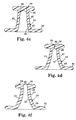
- FIG. 4 a is a perspective view of an exemplary embodiment pinch valve that forms a part of the pinch seal fluid interconnect in accordance with one embodiment of the present invention, with the pinch valve shown in a closed state.
- FIG. 4 b is a top plan view of the exemplary embodiment pinch valve in a closed state of FIG. 3 a.
- FIG. 4 c is a sectional view taken along lines 4 c - 4 c in FIG. 4 b.
- FIG. 4 d is a sectional view taken along lines 4 d - 4 d in FIG. 4 b.
- FIG. 4 e is a top plan view of the exemplary embodiment pinch valve of FIGS. 4 a through 4 d but shown in an opened state.
- FIG. 4 f is a sectional view taken along lines 4 f - 4 f in FIG. 4 e.
- FIG. 5 is a side elevational view similar to FIG. 3 b showing the exemplary embodiment pinch valve engaged with the tubular member and marking fluid flowing into the pinch valve.
- FIG. 6 a is a side elevational view of an exemplary embodiment pinch seal fluid interconnect showing the elements of the fluid interconnect in a disengaged state in accordance with one further embodiment of the present invention.
- FIG. 6 b is a side elevational view similar to FIG. 6 a showing the elements of the fluid interconnect engaged with one another.
- FIG. 7 a is a side elevational view of an exemplary embodiment pinch seal fluid interconnect showing the elements of the fluid interconnect in a disengaged state in accordance with still one further embodiment of the present invention.
- FIG. 7 b is a side elevational view similar to FIG. 7 a showing the elements of the fluid interconnect engaged with one another.
- Exemplary pinch seal fluid interconnect 40 in accordance with one embodiment of the present invention are useable to fluidically couple a replaceable fluid supply container 12 , a manifold such as receiving station 14 , and a printhead cartridge 16 of a thermal inkjet printing system 10 generally illustrated in FIGS. 1, 2, 3 a and 3 b.
- the exemplary printing system 10 shown with its cover open, includes at least one replaceable fluid supply container 12 that is installed in a receiving station 14 .
- the printing system 10 includes two replaceable fluid supply containers 12 .
- marking fluid such as ink
- marking fluid is provided from the replaceable fluid supply containers 12 to at least one inkjet printhead cartridge 16 by way of the receiving station 14 .
- one of the replaceable fluid supply containers 12 contains a single color fluid, such as black ink, while the other replaceable fluid supply container 12 contains multiple colors of fluid, such as cyan, magenta and yellow inks.
- the printing system 10 includes at least two replaceable printhead cartridges 16 , such as one single color printhead cartridge 16 for printing from the black ink supply, and one multi-color printhead cartridge 16 for printing from the cyan, magenta and yellow ink supplies.
- the printing system 10 includes four replaceable printhead cartridges 16 , such that one printhead cartridge 16 is used for printing from each of the black, cyan, magenta and yellow ink supplies.
- the inkjet printhead cartridges 16 are responsive to activation signals from a printer portion 18 to deposit fluid (i.e., ink) on print media 22 .
- fluid i.e., ink
- the printhead cartridges 16 are replenished with fluid from the fluid containers 12 .
- the replaceable fluid containers 12 , receiving station 14 , and the replaceable inkjet printhead cartridges 16 are each part of a scanning carriage 20 that is moved relative to the print media 22 to accomplish printing.
- the printer portion 18 includes a media tray 24 for receiving the print media 22 . As the print media 22 is stepped through a print zone, the scanning carriage 20 moves the printhead cartridges 16 relative to the print media 22 .
- the printer portion 18 selectively activates the printhead cartridges 16 to deposit fluid on print media 22 to thereby accomplish printing.
- the scanning carriage 20 of FIG. 1 slides along a slide rod 26 to print along a width of the print media 22 .
- a positioning means (not shown) is used for precisely positioning the scanning carriage 20 .
- a paper advance mechanism (not shown) moves the print media 22 through the print zone as the scanning carriage 20 is moved along the slide rod 26 .
- Electrical signals are provided to the scanning carriage 20 for selectively activating the printhead cartridges 16 by means of an electrical link, such as a ribbon cable 28 .
- FIG. 2 is a perspective view of a portion of the scanning carriage 20 showing the pair of replaceable fluid containers 12 properly installed in the receiving station 14 .
- each of the replaceable fluid containers 12 includes a latch 30 for securing the replaceable fluid container 12 to the receiving station 14 .
- the receiving station 14 includes a set of keys 32 that interact with corresponding keying features (not shown) on the replaceable fluid containers 12 .
- the keying features on the replaceable fluid containers 12 interact with the keys 32 on the receiving station 14 to ensure that the replaceable fluid containers 12 are compatible with the receiving station 14 .
- FIGS. 3 a and 3 b illustrate the exemplary pinch seal fluid interconnect 40 in disengaged (FIG. 3 a ) and engaged (FIG. 3 b ) states in accordance with one embodiment of the present invention.
- the pinch seal fluid interconnect 40 is defined by a rigid tubular member 42 adapted to releasably receive a pinch valve member 44 .
- the rigid tubular member 42 forms part of the receiving station (i.e., manifold) 14
- the pinch valve member 44 is mounted on the replaceable fluid supply container 12 to form a reliable fluid interconnect therebetween.
- the rigid tubular member 42 could form part of the printhead cartridge 16
- the pinch valve member 44 is mounted on the receiving station 14 to form a reliable fluid interconnect between these two elements of the fluid delivery system of the printing system 10 .
- the exemplary pinch valve member 44 of the pinch seal fluid interconnect 40 has a resilient body 45 having a first end 46 , and an opposite second end 48 in fluid communication with the first end 46 .
- the resilient body 45 also includes an exterior surface 47 and an opposite interior surface 49 .
- the resilient body 45 is substantially cone shaped between the first and second ends 46 and 48 .
- the second end 48 of the resilient body 45 has a greater circumferential dimension than the first end 46 , with a smooth transition therebetween.
- the resilient body 45 is formed of an elastomer material compatible with ink.
- the second end 48 of the resilient body includes an integral mounting flange 50 by which the resilient body 45 of the pinch valve member 44 is retained on the replaceable fluid supply container 12 (see FIGS. 3 a and 3 b ).
- the fluid supply container 12 includes a clamping structure 52 which engages the mounting flange 50 , and secures the resilient body 45 of the pinch valve member 44 to the fluid supply container 12 .
- the resilient nature of the resilient body 45 together with the clamping force provided by the clamping structure 52 acts to form a fluid tight seal at the interface of the pinch valve member 44 and the fluid supply container 12 .
- the first end 46 of the resilient body 45 includes a pair of opposed lips 54 .
- the lips 54 define a normally closed slit 56 (see FIGS. 4 a and 4 b ).
- Applying a compressive force to the exterior surface 47 of the resilient body 45 at the lips 54 deforms the lips 54 from a closed state (see FIGS. 3 a and 4 a - 4 d ), in which the lips 54 are in contact with one another to close the slit 56 and prevent marking fluid 58 from passing through the slit 56 , to an opened state (see FIGS. 3 b , 4 e and 4 f ), in which the lips are spread apart from one another to allow marking fluid 58 to pass through the slit 56 .
- the compressive force is a pair of oppositely directed compressive forces 60 (see FIG. 4 e ) applied to the lips 54 in a direction along (i.e., parallel to) axes 62 of the lips 54 to deform the lips 54 of the resilient body 45 from the closed state to the opened state of the slit 56 .
- the pair of oppositely directed compressive forces 60 are applied to the exterior surface 47 at the lips 54 and at opposite ends of the slit 56 in a direction generally parallel to a longitudinal extent of the slit 56 to deform the lips 54 at the first end 46 of the resilient body 45 from the closed state to the opened state of the slit 56 . Removal of the oppositely directed compressive forces 60 allows the lips 54 to return to their normal state in which the slit 56 is closed.
- the pinch valve member 44 forms a fluid outlet that allows marking fluid 58 to pass out of the fluid supply container 12 (or out of the receiving station 14 ) through the resilient body 45 , from the second end 48 to the first end 46 thereof, and through the open slit 56 (in the opened state of the lips 54 ) and into the receiving station (i.e., manifold) 14 (or into the printhead cartridge 16 ).
- the receiving station i.e., manifold
- the pinch valve member 44 could form a fluid outlet that allows marking fluid 58 to pass out of the fluid supply container 12 (or out of the receiving station 14 ), into the open slit 56 (in the opened state of the lips 54 ), through the resilient body 45 , from the first end 46 to the second end 48 thereof, and into the receiving station (i.e., manifold) 14 (or into the printhead cartridge 16 ).
- the rigid tubular member 42 is adapted to releasably receive the pinch valve member 44 upon engagement of the fluid supply container 12 (or the receiving station 14 ) with the receiving station 14 (or the printhead cartridge 16 ).
- the rigid tubular member 42 has interior wall portions that define a lead-in region 64 and an actuating region 66 of the tubular member 42 .
- the actuating region 66 has a greater pitch than the lead-in portion 64 .
- the lead-in region 64 of the tubular member 42 acts to guide the first end 46 of the resilient body 45 into the actuating region 66 .
- the actuating region 66 applies the oppositely directed compressive forces 60 to the lips 54 in order to deform the lips 54 and move the slit 56 from the closed state to the opened state to allow the marking fluid 58 to pass therethrough.
- the actuating region 66 applies the compressive forces 60 to the lips 54 of the resilient body because the diameter of the actuating region 66 is less than a maximum linear dimension between opposed points 68 (see FIG.
- Pinch seal fluid interconnects 40 establish reliable fluid connections between the fluid supply container 12 and the receiving station 14 , and between the receiving station 14 and the printhead cartridge 16 .
- the pinch seal fluid interconnect 40 of the present invention can also form a reliable fluid connection between a fluid supply container 12 and a printhead cartridge 16 .
- the pinch valve member 44 can act as a fluid outlet or a fluid inlet.
- the pinch seal fluid interconnect 40 is capable of repeated disconnects and reconnects as the ink supply 12 and printhead 16 are removed and installed.
- the resiliency of the pinch valve member 44 and the provision of the lead-in portion 64 of the tubular member 42 permits slight misalignment of the printer components to be connected while still insuring a reliable fluid interconnect. Since the pinch seal fluid interconnect 40 can tolerate some axial misalignment of the printer components to be connected, the printer components do not have to be manufactured to as high tolerances as prior printer components employing fluid interconnects that do not accommodate any misalignment of the printer components. Moreover, the pinch seal fluid interconnect 40 is robust enough to prevent leakage under normal operating and non-operating conditions and under various environmental conditions. In addition, the pinch valve member 44 prevents drooling of fluid when the ink supply 12 and printhead are separated from the printing system.
- the ink supply container 12 includes a guard 70 that prevents damage to the pinch valve member when the ink supply 12 has been removed from the printing system 10 .
- the pinch seal fluid interconnect 40 reliably provides these above features throughout the useful life of the fluid delivery system components of the printing system 10 so as to preclude premature replacement of these components and the associated cost.
- the pinch seal fluid interconnect 40 is relatively easy and inexpensive to manufacture, and relatively simple to incorporate into components used in ink delivery systems of thermal inkjet printing systems.
- FIGS. 6 a and 6 b illustrate an alternative embodiment pinch seal fluid interconnect 80 .
- Like parts are labeled with like numerals except for the addition of the subscript “A” unless otherwise noted.
- This alternative embodiment makes use of a pair of the pinch valve members 44 A, 44 B.
- One pinch valve member 44 A is mounted to the fluid supply container 12 and the other pinch valve member 44 B is mounted to the receiving station 14 .
- the pinch valve members are identical except that the pinch valve member 44 B is made of a softer elastomer material than the pinch valve member 44 A.
- This alternative pinch seal fluid interconnect 80 includes an hour glass shaped rigid tubular member 42 A.
- the tubular member 42 A is mounted to the receiving station 14 such that the tubular member 42 A surrounds the pinch valve member 44 B.
- the tubular member 42 A includes a lead-in region 64 A and an actuating region 66 A that function identical to the lead-in and actuating regions 64 , 66 of the tubular member 42 .
- the pinch valve member 44 B is positioned in the tubular member 42 A such that the first end 46 B of the pinch valve member 44 B is positioned within the lead-in region 64 A of the tubular member 42 A.
- the lead-in region 64 A of the tubular member 42 A acts to guide the first end 46 A of the pinch valve member 44 A into the actuating region 66 A.
- the lips 54 A at the first end 46 A of the pinch valve member 44 A bear against the lips 54 B at the first end 46 B of the pinch valve member 44 B which causes the pinch valve member 44 B to deform along its longitudinal extent (see FIG. 6 b ) since it is of a softer elastomer material than the pinch valve member 44 A.
- the pinch valve member 44 B could include an internal rigidifying tubular element 82 , which would provide the necessary stiffness to allow the pinch valve member 44 A to deform the pinch valve member 44 B along its longitudinal extent. Removal of the ink container 12 from the receiving station allows the pinch valve member 44 B to return to its original non-deformed state, with the lips 54 A, 54 B in a closed state.
- the pinch valve member 44 B could be formed so as to be normally in the opened state.
- the lips 54 B of the pinch valve member 44 B would normally be positioned within the actuating region 66 A of the tubular member 42 A so that the actuating region 66 A would hold the lips 54 B of the pinch valve member 44 B in the closed state.
- the lips 54 A at the first end 46 A of the pinch valve member 44 A would bear against the lips 54 B at the first end 46 B of the pinch valve member 44 B which would cause the pinch valve member 44 B to deform along its longitudinal extent since it is of a softer elastomer material than the pinch valve member 44 A.
- FIGS. 7 a and 7 b illustrate an alternative embodiment pinch seal fluid interconnect 90 .
- the pinch valve members 44 A and 44 B are formed of the same elastomer material and without the rigidifying tubular element 82 .
- the second end 48 B of the pinch valve member 44 B includes a circumferential groove 92 for receiving an O-ring 94 .
- the second end 48 B of the pinch valve member 44 B is received within a bore 96 on the receiving station 14 .
- the O-ring 94 forms a fluid tight seal with the bore 96 and allows the pinch valve member 44 B to move relative to the receiving station 14 along the bore 96 .
- a spring member 98 acts between the receiving station 14 and the second end 48 B of the pinch valve member 44 B to bias the pinch valve member to the position shown in FIG. 7 a wherein the lips 54 B of the pinch valve member 44 B are in a closed state.
- the lead-in region 64 A of the tubular member 42 A acts to guide the first end 46 A of the pinch valve member 44 A into the actuating region 66 A.
- the lips 54 A at the first end 46 A of the pinch valve member 44 A bear against the lips 54 B at the first end 46 B of the pinch valve member 44 B which causes the pinch valve member 44 B to move along the bore 96 against the bias of the spring 98 (see FIG. 7 b ).
- Pinch seal fluid interconnects 80 , 90 establish reliable fluid connections between the fluid supply container 12 and the receiving station 14 , and between the receiving station 14 and the printhead cartridge 16 .
- the pinch seal fluid interconnect 80 , 90 of the present invention can also form a reliable fluid connection between a fluid supply container 12 and a printhead cartridge 16 .
- the pinch valve members 44 A, 44 B can pass fluid in either direction.
- the pinch seal fluid interconnect 80 , 90 is capable of repeated disconnects and reconnects as the ink supply 12 and printhead 16 are removed and installed.
- the pinch seal fluid interconnect 80 , 90 is robust enough to prevent leakage under normal operating and non-operating conditions and under various environmental conditions.
- the pinch valve members 44 A, 44 B prevent drooling of fluid when the ink supply 12 and printhead 16 are separated from the printing system. Moreover, the use of the pair of pinch valve members 44 A, 44 B minimizes air introduced and ink loss upon disconnects and reconnects of the printer components.
- the pinch seal fluid interconnect 80 , 90 reliably provides these above features throughout the useful life of the fluid delivery system components of the printing system 10 so as to preclude premature replacement of these components and the associated cost.
- the pinch seal fluid interconnect 80 , 90 is relatively easy and inexpensive to manufacture, and relatively simple to incorporate into components used in ink delivery systems of thermal inkjet printing systems.
Landscapes
- Ink Jet (AREA)
Abstract
Description
- This invention relates to printing devices. In particular, the present invention is a fluid delivery system that employs pinch seal fluid interconnects to fluidly interconnect separable fluid delivery system components.
- Throughout the business world, inkjet printing systems are extensively used for image reproduction. Inkjet printers frequently make use of an inkjet printhead mounted within a carriage that is moved back and forth across print media, such as paper. As the printhead is moved relative to the print media, a control system activates the printhead to deposit or eject ink droplets onto the print media to form images and text. Such systems may be used in a wide variety of applications, including computer printers, plotters, copiers and facsimile machines.
- Ink is provided to the printhead by a supply of ink that is either integral with the printhead, as in the case of a disposable print cartridge, or by a supply of ink that is replaceable separate from the printhead. One type of previously used printing system makes use of an ink supply that is carried with the carriage. This ink supply has been formed integral with the printhead, whereupon the entire printhead and ink supply are replaced when ink is exhausted. Alternatively, the ink supply can be carried with the carriage and be separately replaceable from the printhead. As a further alternative, the ink supply can be mounted to the printing system such that the ink supply does not move with the carriage. For the case where the ink supply is not carried with the carriage, the ink supply can be in fluid communication with the printhead to replenish the printhead or the printhead can be intermittently connected with the ink supply by positioning the printhead proximate to a filling station to which the ink supply is connected whereupon the printhead is replenished with ink from the refilling station. Generally, when the ink supply is separately replaceable, the ink supply is replaced when exhausted. The printhead is then replaced at the end of printhead life. Regardless of where the ink supply is located within the printing system, it is critical that the ink supply provides a reliable supply of ink to the inkjet printhead.
- No matter what the arrangement of the ink supply and printhead, it is crucial that the replaceable ink supply and printhead be capable of establishing a reliable fluid connection with the printing system or with one another. This fluid interconnection should be capable of repeated disconnects and reconnects as the ink supply and printhead are removed and installed. Moreover, the fluid interconnect should be robust enough to prevent leakage under normal operating and non-operating conditions and under various environmental conditions. In addition, the fluid interconnects should prevent drooling of fluid when the ink supply and printhead are separated from the printing system. The fluid interconnections between the ink supply, printing system and printhead should reliably provide these features throughout the useful life of these fluid delivery system components so as to preclude premature replacement of these components and the associated cost. Lastly, the fluid interconnect should be relatively easy and inexpensive to manufacture, and relatively simple to incorporate into these components used in ink delivery systems of thermal inkjet printing systems.
- The present invention is a marking fluid valve for a marking fluid delivery system of a media marking device. The marking fluid valve comprises a resilient body having first and second opposite ends in fluid communication with one another. The first end of the resilient body includes a pair of opposed lips. The pair of opposed lips define a normally closed slit extending therebetween, wherein compressing the first end of the resilient body along the axis of the lips deforms the resilient body from a closed position, in which the lips are in contact with one another to close the slit and prevent marking fluid from passing through the slit, to an open position, in which the lips are spread at least partially apart from one another to enable marking fluid to pass through the slit.
- The pinch seal interconnects function to provide reliable fluid interconnects between fluid delivery system components, such as fluid supply containers, printheads and manifold structures of a printing device. The pinch seal fluid interconnects prevent drooling of fluid, when fluid delivery system components are separated.
- The accompanying drawings are included to provide a further understanding of the present invention and are incorporated in and constitute a part of this specification. The drawings illustrate the embodiments of the present invention and together with the description serve to explain the principles of the invention. Other embodiments of the present invention and many of the intended advantages of the present invention will be readily appreciated as the same become better understood by reference to the following detailed description when considered in connection with the accompanying drawings, in which like reference numerals designate like parts throughout the figures thereof, and wherein:
- FIG. 1 is a perspective view of an exemplary printing system with a cover opened to show a plurality of replaceable ink containers, a receiving station, and a plurality of replaceable printhead cartridges incorporating pinch seal fluid interconnects in accordance with one embodiment of the present invention.
- FIG. 2 is a perspective view a portion of a scanning carriage showing the replaceable ink containers positioned in the receiving station which includes a manifold that provides fluid communication between the replaceable ink containers and one or more printhead cartridges.
- FIG. 3 a is a side elevational view of an exemplary embodiment of the pinch valve positioned to be received by a tubular member that together define the pinch seal fluid interconnect of one embodiment of the present invention.
- FIG. 3 b is a side elevational view similar to FIG. 3a showing the exemplary embodiment of the pinch valve engaged with the tubular member and marking fluid flowing out of the pinch valve.
- FIG. 4 a is a perspective view of an exemplary embodiment pinch valve that forms a part of the pinch seal fluid interconnect in accordance with one embodiment of the present invention, with the pinch valve shown in a closed state.
- FIG. 4 b is a top plan view of the exemplary embodiment pinch valve in a closed state of FIG. 3a.
- FIG. 4 c is a sectional view taken along
lines 4 c-4 c in FIG. 4b. - FIG. 4 d is a sectional view taken along
lines 4 d-4 d in FIG. 4b. - FIG. 4 e is a top plan view of the exemplary embodiment pinch valve of FIGS. 4a through 4 d but shown in an opened state.
- FIG. 4 f is a sectional view taken along
lines 4 f-4 f in FIG. 4e. - FIG. 5 is a side elevational view similar to FIG. 3 b showing the exemplary embodiment pinch valve engaged with the tubular member and marking fluid flowing into the pinch valve.
- FIG. 6 a is a side elevational view of an exemplary embodiment pinch seal fluid interconnect showing the elements of the fluid interconnect in a disengaged state in accordance with one further embodiment of the present invention.
- FIG. 6 b is a side elevational view similar to FIG. 6a showing the elements of the fluid interconnect engaged with one another.
- FIG. 7 a is a side elevational view of an exemplary embodiment pinch seal fluid interconnect showing the elements of the fluid interconnect in a disengaged state in accordance with still one further embodiment of the present invention.
- FIG. 7 b is a side elevational view similar to FIG. 7a showing the elements of the fluid interconnect engaged with one another.
- Exemplary pinch seal fluid interconnect 40 (see FIGS. 3a and 3 b) in accordance with one embodiment of the present invention are useable to fluidically couple a replaceable
fluid supply container 12, a manifold such as receivingstation 14, and aprinthead cartridge 16 of a thermalinkjet printing system 10 generally illustrated in FIGS. 1, 2, 3 a and 3 b. - In FIG. 1, the
exemplary printing system 10, shown with its cover open, includes at least one replaceablefluid supply container 12 that is installed in a receivingstation 14. In one preferred embodiment, theprinting system 10 includes two replaceablefluid supply containers 12. With the replaceablefluid supply containers 12 properly installed into the receivingstation 14, marking fluid, such as ink, is provided from the replaceablefluid supply containers 12 to at least oneinkjet printhead cartridge 16 by way of the receivingstation 14. In one preferred embodiment, one of the replaceablefluid supply containers 12 contains a single color fluid, such as black ink, while the other replaceablefluid supply container 12 contains multiple colors of fluid, such as cyan, magenta and yellow inks. Generally, theprinting system 10 includes at least tworeplaceable printhead cartridges 16, such as one singlecolor printhead cartridge 16 for printing from the black ink supply, and onemulti-color printhead cartridge 16 for printing from the cyan, magenta and yellow ink supplies. In one embodiment, theprinting system 10 includes fourreplaceable printhead cartridges 16, such that oneprinthead cartridge 16 is used for printing from each of the black, cyan, magenta and yellow ink supplies. - In operation, the
inkjet printhead cartridges 16 are responsive to activation signals from aprinter portion 18 to deposit fluid (i.e., ink) onprint media 22. As the fluid is ejected from theprinthead cartridges 16, theprinthead cartridges 16 are replenished with fluid from thefluid containers 12. In one preferred embodiment, thereplaceable fluid containers 12, receivingstation 14, and the replaceableinkjet printhead cartridges 16 are each part of ascanning carriage 20 that is moved relative to theprint media 22 to accomplish printing. Theprinter portion 18 includes amedia tray 24 for receiving theprint media 22. As theprint media 22 is stepped through a print zone, thescanning carriage 20 moves theprinthead cartridges 16 relative to theprint media 22. Theprinter portion 18 selectively activates theprinthead cartridges 16 to deposit fluid onprint media 22 to thereby accomplish printing. - The
scanning carriage 20 of FIG. 1 slides along aslide rod 26 to print along a width of theprint media 22. A positioning means (not shown) is used for precisely positioning thescanning carriage 20. In addition, a paper advance mechanism (not shown) moves theprint media 22 through the print zone as thescanning carriage 20 is moved along theslide rod 26. Electrical signals are provided to thescanning carriage 20 for selectively activating theprinthead cartridges 16 by means of an electrical link, such as aribbon cable 28. - FIG. 2 is a perspective view of a portion of the
scanning carriage 20 showing the pair of replaceablefluid containers 12 properly installed in the receivingstation 14. For clarity, only a singleinkjet printhead cartridge 16 is shown in fluid communication with the receivingstation 14. As seen in FIG. 2, each of thereplaceable fluid containers 12 includes alatch 30 for securing thereplaceable fluid container 12 to the receivingstation 14. In addition, the receivingstation 14 includes a set ofkeys 32 that interact with corresponding keying features (not shown) on thereplaceable fluid containers 12. The keying features on thereplaceable fluid containers 12 interact with thekeys 32 on the receivingstation 14 to ensure that thereplaceable fluid containers 12 are compatible with the receivingstation 14. - FIGS. 3 a and 3 b illustrate the exemplary pinch
seal fluid interconnect 40 in disengaged (FIG. 3a) and engaged (FIG. 3b) states in accordance with one embodiment of the present invention. The pinchseal fluid interconnect 40 is defined by a rigidtubular member 42 adapted to releasably receive apinch valve member 44. For the purposes of this discussion, therigid tubular member 42 forms part of the receiving station (i.e., manifold) 14, while thepinch valve member 44 is mounted on the replaceablefluid supply container 12 to form a reliable fluid interconnect therebetween. However, it is to be understood that therigid tubular member 42 could form part of theprinthead cartridge 16, while thepinch valve member 44 is mounted on the receivingstation 14 to form a reliable fluid interconnect between these two elements of the fluid delivery system of theprinting system 10. - As seen best in FIGS. 4 a-4 f, the exemplary
pinch valve member 44 of the pinchseal fluid interconnect 40 has aresilient body 45 having afirst end 46, and an oppositesecond end 48 in fluid communication with thefirst end 46. Theresilient body 45 also includes anexterior surface 47 and an oppositeinterior surface 49. As seen best in FIGS. 4a, 4 c, 4 d and 4 f, theresilient body 45 is substantially cone shaped between the first and second ends 46 and 48. In particular, thesecond end 48 of theresilient body 45 has a greater circumferential dimension than thefirst end 46, with a smooth transition therebetween. In one preferred embodiment, theresilient body 45 is formed of an elastomer material compatible with ink. Thesecond end 48 of the resilient body includes an integral mountingflange 50 by which theresilient body 45 of thepinch valve member 44 is retained on the replaceable fluid supply container 12 (see FIGS. 3a and 3 b). To accomplish this, thefluid supply container 12 includes a clampingstructure 52 which engages the mountingflange 50, and secures theresilient body 45 of thepinch valve member 44 to thefluid supply container 12. The resilient nature of theresilient body 45 together with the clamping force provided by the clampingstructure 52 acts to form a fluid tight seal at the interface of thepinch valve member 44 and thefluid supply container 12. - The
first end 46 of theresilient body 45 includes a pair ofopposed lips 54. Thelips 54 define a normally closed slit 56 (see FIGS. 4a and 4 b). Applying a compressive force to theexterior surface 47 of theresilient body 45 at thelips 54 deforms thelips 54 from a closed state (see FIGS. 3a and 4 a-4 d), in which thelips 54 are in contact with one another to close theslit 56 and prevent markingfluid 58 from passing through theslit 56, to an opened state (see FIGS. 3b, 4 e and 4 f), in which the lips are spread apart from one another to allow markingfluid 58 to pass through theslit 56. In particular, the compressive force is a pair of oppositely directed compressive forces 60 (see FIG. 4e) applied to thelips 54 in a direction along (i.e., parallel to) axes 62 of thelips 54 to deform thelips 54 of theresilient body 45 from the closed state to the opened state of theslit 56. In other words, the pair of oppositely directed compressive forces 60 (see FIG. 4e) are applied to theexterior surface 47 at thelips 54 and at opposite ends of theslit 56 in a direction generally parallel to a longitudinal extent of theslit 56 to deform thelips 54 at thefirst end 46 of theresilient body 45 from the closed state to the opened state of theslit 56. Removal of the oppositely directedcompressive forces 60 allows thelips 54 to return to their normal state in which theslit 56 is closed. - In FIGS. 3 a and 3 b, the
pinch valve member 44 forms a fluid outlet that allows markingfluid 58 to pass out of the fluid supply container 12 (or out of the receiving station 14) through theresilient body 45, from thesecond end 48 to thefirst end 46 thereof, and through the open slit 56 (in the opened state of the lips 54) and into the receiving station (i.e., manifold) 14 (or into the printhead cartridge 16). Alternatively, as illustrated in FIG. 5, thepinch valve member 44 could form a fluid outlet that allows markingfluid 58 to pass out of the fluid supply container 12 (or out of the receiving station 14), into the open slit 56 (in the opened state of the lips 54), through theresilient body 45, from thefirst end 46 to thesecond end 48 thereof, and into the receiving station (i.e., manifold) 14 (or into the printhead cartridge 16). - As seen best in FIGS. 3 a and 3 b, the
rigid tubular member 42 is adapted to releasably receive thepinch valve member 44 upon engagement of the fluid supply container 12 (or the receiving station 14) with the receiving station 14 (or the printhead cartridge 16). Therigid tubular member 42 has interior wall portions that define a lead-inregion 64 and anactuating region 66 of thetubular member 42. Theactuating region 66 has a greater pitch than the lead-inportion 64. As can be best viewed by comparing FIGS. 3a and 3 b, upon initial engagement of thecontainer 12 with the receivingstation 14, the lead-inregion 64 of thetubular member 42 acts to guide thefirst end 46 of theresilient body 45 into theactuating region 66. Upon full engagement of thecontainer 12 with the receivingstation 14, theactuating region 66 applies the oppositely directedcompressive forces 60 to thelips 54 in order to deform thelips 54 and move theslit 56 from the closed state to the opened state to allow the markingfluid 58 to pass therethrough. Theactuating region 66 applies thecompressive forces 60 to thelips 54 of the resilient body because the diameter of theactuating region 66 is less than a maximum linear dimension between opposed points 68 (see FIG. 4b) on the perimeter of the resilient body atlips 54. Because the diameter of the actuating region is less than the maximum linear dimension at thelips 54 of theresilient body 45, thelips 54 at thefirst end 46 are deformed when they enter into theactuating region 66. - Pinch seal fluid interconnects 40 establish reliable fluid connections between the
fluid supply container 12 and the receivingstation 14, and between the receivingstation 14 and theprinthead cartridge 16. However, it is to be understood that the pinchseal fluid interconnect 40 of the present invention can also form a reliable fluid connection between afluid supply container 12 and aprinthead cartridge 16. Moreover, it is to be understood that thepinch valve member 44 can act as a fluid outlet or a fluid inlet. In addition the pinchseal fluid interconnect 40 is capable of repeated disconnects and reconnects as theink supply 12 andprinthead 16 are removed and installed. Further, the resiliency of thepinch valve member 44 and the provision of the lead-inportion 64 of thetubular member 42 permits slight misalignment of the printer components to be connected while still insuring a reliable fluid interconnect. Since the pinchseal fluid interconnect 40 can tolerate some axial misalignment of the printer components to be connected, the printer components do not have to be manufactured to as high tolerances as prior printer components employing fluid interconnects that do not accommodate any misalignment of the printer components. Moreover, the pinchseal fluid interconnect 40 is robust enough to prevent leakage under normal operating and non-operating conditions and under various environmental conditions. In addition, thepinch valve member 44 prevents drooling of fluid when theink supply 12 and printhead are separated from the printing system. To this end, theink supply container 12 includes aguard 70 that prevents damage to the pinch valve member when theink supply 12 has been removed from theprinting system 10. The pinchseal fluid interconnect 40 reliably provides these above features throughout the useful life of the fluid delivery system components of theprinting system 10 so as to preclude premature replacement of these components and the associated cost. Lastly, the pinchseal fluid interconnect 40 is relatively easy and inexpensive to manufacture, and relatively simple to incorporate into components used in ink delivery systems of thermal inkjet printing systems. - FIGS. 6 a and 6 b illustrate an alternative embodiment pinch
seal fluid interconnect 80. Like parts are labeled with like numerals except for the addition of the subscript “A” unless otherwise noted. This alternative embodiment makes use of a pair of thepinch valve members pinch valve member 44A is mounted to thefluid supply container 12 and the otherpinch valve member 44B is mounted to the receivingstation 14. The pinch valve members are identical except that thepinch valve member 44B is made of a softer elastomer material than thepinch valve member 44A. This alternative pinchseal fluid interconnect 80 includes an hour glass shaped rigidtubular member 42A. Thetubular member 42A is mounted to the receivingstation 14 such that thetubular member 42A surrounds thepinch valve member 44B. Thetubular member 42A includes a lead-inregion 64A and anactuating region 66A that function identical to the lead-in andactuating regions tubular member 42. Thepinch valve member 44B is positioned in thetubular member 42A such that thefirst end 46B of thepinch valve member 44B is positioned within the lead-inregion 64A of thetubular member 42A. - Upon initial engagement of the
container 12 with the receivingstation 14, the lead-inregion 64A of thetubular member 42A acts to guide thefirst end 46A of thepinch valve member 44A into theactuating region 66A. Upon full engagement of thecontainer 12 with the receivingstation 14, thelips 54A at thefirst end 46A of thepinch valve member 44A bear against thelips 54B at thefirst end 46B of thepinch valve member 44B which causes thepinch valve member 44B to deform along its longitudinal extent (see FIG. 6b) since it is of a softer elastomer material than thepinch valve member 44A. This causes thelips pinch valve members actuating region 66A of thetubular member 42A which applies the oppositely directedcompressive forces 60 to the exterior surfaces 47A, 47B of thepinch valve members lips slits fluid 58 to pass therethrough. Theactuating region 66A applies thecompressive forces 60 to thelips actuating region 66A is less than a maximum linear dimension of thelips pinch valve member 44B of a softer elastomer material than thepinch valve member 44A, the pinch valve member could include an internalrigidifying tubular element 82, which would provide the necessary stiffness to allow thepinch valve member 44A to deform thepinch valve member 44B along its longitudinal extent. Removal of theink container 12 from the receiving station allows thepinch valve member 44B to return to its original non-deformed state, with thelips - It is to be understood that as an alternative, the
pinch valve member 44B could be formed so as to be normally in the opened state. In this version, thelips 54B of thepinch valve member 44B would normally be positioned within theactuating region 66A of thetubular member 42A so that theactuating region 66A would hold thelips 54B of thepinch valve member 44B in the closed state. In this version, upon full engagement of thecontainer 12 with the receivingstation 14, thelips 54A at thefirst end 46A of thepinch valve member 44A would bear against thelips 54B at thefirst end 46B of thepinch valve member 44B which would cause thepinch valve member 44B to deform along its longitudinal extent since it is of a softer elastomer material than thepinch valve member 44A. This causes thelips 54A at thefirst end 46A of thepinch valve member 44A to enter theactuating region 66A of thetubular member 42A which deforms thelips 54A and moves theslit 56A from its closed state to its opened state, while thelips 54B of thepinch valve member 44B are moved below theactuating region 66A which allows thelips 54B of thepinch valve member 44B to return to their normal state wherein theslit 56B moves from the closed state to the normally opened state to allow the markingfluid 58 to pass therethrough. - FIGS. 7 a and 7 b illustrate an alternative embodiment pinch
seal fluid interconnect 90. In this embodiment, thepinch valve members tubular element 82. In this embodiment, thesecond end 48B of thepinch valve member 44B includes acircumferential groove 92 for receiving an O-ring 94. Thesecond end 48B of thepinch valve member 44B is received within abore 96 on the receivingstation 14. The O-ring 94 forms a fluid tight seal with thebore 96 and allows thepinch valve member 44B to move relative to the receivingstation 14 along thebore 96. Aspring member 98 acts between the receivingstation 14 and thesecond end 48B of thepinch valve member 44B to bias the pinch valve member to the position shown in FIG. 7a wherein thelips 54B of thepinch valve member 44B are in a closed state. - Upon initial engagement of the
container 12 with the receivingstation 14, the lead-inregion 64A of thetubular member 42A acts to guide thefirst end 46A of thepinch valve member 44A into theactuating region 66A. Upon full engagement of thecontainer 12 with the receivingstation 14, thelips 54A at thefirst end 46A of thepinch valve member 44A bear against thelips 54B at thefirst end 46B of thepinch valve member 44B which causes thepinch valve member 44B to move along thebore 96 against the bias of the spring 98 (see FIG. 7b). This causes thelips pinch valve members actuating region 66A of thetubular member 42A which applies the oppositely directedcompressive forces 60 to the exterior surfaces 47A, 47B of thelips pinch valve members lips slits fluid 58 to pass therethrough. Theactuating region 66A applies thecompressive forces 60 to thelips actuating region 66A is less than a maximum linear dimension of thelips ink container 12 from the receiving station allows thepinch valve member 44B to return to its starting position and thelips - Pinch seal fluid interconnects 80, 90 establish reliable fluid connections between the
fluid supply container 12 and the receivingstation 14, and between the receivingstation 14 and theprinthead cartridge 16. However, it is to be understood that the pinchseal fluid interconnect fluid supply container 12 and aprinthead cartridge 16. Moreover, it is to be understood that thepinch valve members seal fluid interconnect ink supply 12 andprinthead 16 are removed and installed. Moreover, the pinchseal fluid interconnect pinch valve members ink supply 12 andprinthead 16 are separated from the printing system. Moreover, the use of the pair ofpinch valve members seal fluid interconnect printing system 10 so as to preclude premature replacement of these components and the associated cost. Lastly, the pinchseal fluid interconnect - Although the present invention has been described with reference to preferred embodiments, workers skilled in the art will recognize that changes may be made in form and detail without departing from the spirit and scope of the invention.
Claims (35)
Priority Applications (1)
| Application Number | Priority Date | Filing Date | Title |
|---|---|---|---|
| US10/127,885 US6648458B2 (en) | 2002-04-23 | 2002-04-23 | Pinch seal providing fluid interconnects between fluid delivery system components |
Applications Claiming Priority (1)
| Application Number | Priority Date | Filing Date | Title |
|---|---|---|---|
| US10/127,885 US6648458B2 (en) | 2002-04-23 | 2002-04-23 | Pinch seal providing fluid interconnects between fluid delivery system components |
Publications (2)
| Publication Number | Publication Date |
|---|---|
| US20030197765A1 true US20030197765A1 (en) | 2003-10-23 |
| US6648458B2 US6648458B2 (en) | 2003-11-18 |
Family
ID=29215351
Family Applications (1)
| Application Number | Title | Priority Date | Filing Date |
|---|---|---|---|
| US10/127,885 Expired - Fee Related US6648458B2 (en) | 2002-04-23 | 2002-04-23 | Pinch seal providing fluid interconnects between fluid delivery system components |
Country Status (1)
| Country | Link |
|---|---|
| US (1) | US6648458B2 (en) |
Cited By (11)
| Publication number | Priority date | Publication date | Assignee | Title |
|---|---|---|---|---|
| EP1533125A1 (en) * | 2003-11-19 | 2005-05-25 | 3T Supplies AG | Ink cartridge, ink cartridge unit and ink jet printhead |
| EP2008825A1 (en) | 2007-06-29 | 2008-12-31 | World Network Co., LTD. | Ink storage device and an ink cartidge of the same |
| US20090179968A1 (en) * | 2008-01-16 | 2009-07-16 | Silverbrook Research Pty Ltd | Low insertion force fluid coupling |
| WO2009089566A1 (en) * | 2008-01-16 | 2009-07-23 | Silverbrook Research Pty Ltd | Low insertion force fluid coupling |
| EP2237965A4 (en) * | 2008-01-16 | 2011-02-23 | Silverbrook Res Pty Ltd | Multiple conduit fluid coupling with leakage flow control |
| EP2109541A4 (en) * | 2007-01-30 | 2012-04-04 | Hewlett Packard Development Co | Over-molded fluid interconnect |
| JP2023035278A (en) * | 2021-08-31 | 2023-03-13 | ブラザー工業株式会社 | liquid storage bottle |
| JP2023051714A (en) * | 2021-09-30 | 2023-04-11 | セイコーエプソン株式会社 | Ink supply container |
| US12296599B2 (en) | 2021-08-31 | 2025-05-13 | Brother Kogyo Kabushiki Kaisha | Liquid containment bottle and liquid supply apparatus |
| US12304210B2 (en) | 2021-08-31 | 2025-05-20 | Brother Kogyo Kabushiki Kaisha | Liquid container |
| US12502892B2 (en) | 2021-08-31 | 2025-12-23 | Brother Kogyo Kabushiki Kaisha | Liquid containment bottle and liquid supply apparatus |
Families Citing this family (1)
| Publication number | Priority date | Publication date | Assignee | Title |
|---|---|---|---|---|
| US8434853B1 (en) | 2011-10-25 | 2013-05-07 | Hewlett-Packard Development Company, L.P. | Printhead cap assembly |
Citations (4)
| Publication number | Priority date | Publication date | Assignee | Title |
|---|---|---|---|---|
| US6072509A (en) * | 1997-06-03 | 2000-06-06 | Eastman Kodak Company | Microfluidic printing with ink volume control |
| US6078340A (en) * | 1997-09-26 | 2000-06-20 | Eastman Kodak Company | Using silver salts and reducing reagents in microfluidic printing |
| US6091433A (en) * | 1997-06-11 | 2000-07-18 | Eastman Kodak Company | Contact microfluidic printing apparatus |
| US6137501A (en) * | 1997-09-19 | 2000-10-24 | Eastman Kodak Company | Addressing circuitry for microfluidic printing apparatus |
Family Cites Families (5)
| Publication number | Priority date | Publication date | Assignee | Title |
|---|---|---|---|---|
| US5699091A (en) | 1994-12-22 | 1997-12-16 | Hewlett-Packard Company | Replaceable part with integral memory for usage, calibration and other data |
| US6017118A (en) | 1995-04-27 | 2000-01-25 | Hewlett-Packard Company | High performance ink container with efficient construction |
| US5721576A (en) | 1995-12-04 | 1998-02-24 | Hewlett-Packard Company | Refill kit and method for refilling an ink supply for an ink-jet printer |
| US6130695A (en) | 1995-04-27 | 2000-10-10 | Hewlett-Packard Company | Ink delivery system adapter |
| US6039441A (en) | 1995-09-28 | 2000-03-21 | Fuji Xerox Co., Ltd. | Ink jet recording unit |
-
2002
- 2002-04-23 US US10/127,885 patent/US6648458B2/en not_active Expired - Fee Related
Patent Citations (4)
| Publication number | Priority date | Publication date | Assignee | Title |
|---|---|---|---|---|
| US6072509A (en) * | 1997-06-03 | 2000-06-06 | Eastman Kodak Company | Microfluidic printing with ink volume control |
| US6091433A (en) * | 1997-06-11 | 2000-07-18 | Eastman Kodak Company | Contact microfluidic printing apparatus |
| US6137501A (en) * | 1997-09-19 | 2000-10-24 | Eastman Kodak Company | Addressing circuitry for microfluidic printing apparatus |
| US6078340A (en) * | 1997-09-26 | 2000-06-20 | Eastman Kodak Company | Using silver salts and reducing reagents in microfluidic printing |
Cited By (19)
| Publication number | Priority date | Publication date | Assignee | Title |
|---|---|---|---|---|
| US20060001709A1 (en) * | 2003-11-19 | 2006-01-05 | 3T Supplies Ag | Ink cartridge, ink cartridge unit and inkjet printing head |
| EP1533125A1 (en) * | 2003-11-19 | 2005-05-25 | 3T Supplies AG | Ink cartridge, ink cartridge unit and ink jet printhead |
| US7625078B2 (en) | 2003-11-19 | 2009-12-01 | 3T Supplies Ag | Ink cartridge, ink cartridge unit and inkjet printing head |
| EP2109541A4 (en) * | 2007-01-30 | 2012-04-04 | Hewlett Packard Development Co | Over-molded fluid interconnect |
| KR101019724B1 (en) * | 2007-06-29 | 2011-03-07 | 월드 네트워크 컴퍼니 리미티드 | Ink Storage and Ink Cartridges |
| EP2008825A1 (en) | 2007-06-29 | 2008-12-31 | World Network Co., LTD. | Ink storage device and an ink cartidge of the same |
| WO2009089566A1 (en) * | 2008-01-16 | 2009-07-23 | Silverbrook Research Pty Ltd | Low insertion force fluid coupling |
| EP2237965A4 (en) * | 2008-01-16 | 2011-02-23 | Silverbrook Res Pty Ltd | Multiple conduit fluid coupling with leakage flow control |
| US7862162B2 (en) | 2008-01-16 | 2011-01-04 | Silverbrook Research Pty Ltd | Low insertion force fluid coupling |
| US20110080455A1 (en) * | 2008-01-16 | 2011-04-07 | Silverbrook Research Pty Ltd | Fluid coupling |
| US8113638B2 (en) | 2008-01-16 | 2012-02-14 | Silverbrook Research Pty Ltd | Fluid coupling |
| US20090179968A1 (en) * | 2008-01-16 | 2009-07-16 | Silverbrook Research Pty Ltd | Low insertion force fluid coupling |
| JP2023035278A (en) * | 2021-08-31 | 2023-03-13 | ブラザー工業株式会社 | liquid storage bottle |
| US12296599B2 (en) | 2021-08-31 | 2025-05-13 | Brother Kogyo Kabushiki Kaisha | Liquid containment bottle and liquid supply apparatus |
| US12296596B2 (en) | 2021-08-31 | 2025-05-13 | Brother Kogyo Kabushiki Kaisha | Liquid containment bottle and liquid supply apparatus |
| US12304210B2 (en) | 2021-08-31 | 2025-05-20 | Brother Kogyo Kabushiki Kaisha | Liquid container |
| JP7700591B2 (en) | 2021-08-31 | 2025-07-01 | ブラザー工業株式会社 | Liquid containing bottle |
| US12502892B2 (en) | 2021-08-31 | 2025-12-23 | Brother Kogyo Kabushiki Kaisha | Liquid containment bottle and liquid supply apparatus |
| JP2023051714A (en) * | 2021-09-30 | 2023-04-11 | セイコーエプソン株式会社 | Ink supply container |
Also Published As
| Publication number | Publication date |
|---|---|
| US6648458B2 (en) | 2003-11-18 |
Similar Documents
| Publication | Publication Date | Title |
|---|---|---|
| US6431697B1 (en) | Replaceable ink container having a separately attachable latch and method for assembling the container | |
| US6488368B2 (en) | Manifold for providing fluid connections between carriage-mounted ink containers and printheads | |
| EP1219436B1 (en) | Apparatus for providing ink to an ink jet print head | |
| EP1431042B1 (en) | Replaceable ink container for an inkjet printing system | |
| US6375315B1 (en) | Replaceable ink container for an inkjet printing system | |
| JP4332352B2 (en) | Pigment fluid delivery system | |
| US6648458B2 (en) | Pinch seal providing fluid interconnects between fluid delivery system components | |
| EP1223039A1 (en) | Printhead air management using unsaturated ink | |
| JPH10157156A (en) | Fluid adapter for ink jet print cartridge | |
| US6631982B2 (en) | Liquid ejecting apparatus | |
| JP2000043281A (en) | Unitary capping system for multiple inkjet print head | |
| AU2002254672B2 (en) | Ink container configured to establish reliable fluidic connection to a receiving station | |
| EP1120257A2 (en) | Print head unit | |
| JP2004524197A5 (en) | ||
| US6145967A (en) | Method and apparatus for configuring a fluid interconnect for an ink-jet printhead | |
| US6827432B2 (en) | Replaceable ink container for an inkjet printing system | |
| KR20010082030A (en) | Replaceable ink container for an inkjet printing system | |
| JP2004017356A (en) | Inkjet image forming equipment | |
| US20050128261A1 (en) | Ink supply system | |
| JP2005153523A (en) | Ink supply system | |
| EP1533127A1 (en) | Ink supply system | |
| HK1058335B (en) | Ink container configured to establish reliable fluidic connection to a receiving station | |
| HK1068011B (en) | Replaceable ink container for an inkjet printing system |
Legal Events
| Date | Code | Title | Description |
|---|---|---|---|
| AS | Assignment |
Owner name: HEWLETT-PACKARD COMPANY, COLORADO Free format text: ASSIGNMENT OF ASSIGNORS INTEREST;ASSIGNORS:DOD, ERIC S.;STATHERN, RALPH L.;BLYTHE, GREGORY W.;REEL/FRAME:013772/0085;SIGNING DATES FROM 20020409 TO 20020422 |
|
| AS | Assignment |
Owner name: HEWLETT-PACKARD DEVELOPMENT COMPANY, L.P., COLORADO Free format text: ASSIGNMENT OF ASSIGNORS INTEREST;ASSIGNOR:HEWLETT-PACKARD COMPANY;REEL/FRAME:013776/0928 Effective date: 20030131 Owner name: HEWLETT-PACKARD DEVELOPMENT COMPANY, L.P., COLORAD Free format text: ASSIGNMENT OF ASSIGNORS INTEREST;ASSIGNOR:HEWLETT-PACKARD COMPANY;REEL/FRAME:013776/0928 Effective date: 20030131 Owner name: HEWLETT-PACKARD DEVELOPMENT COMPANY, L.P.,COLORADO Free format text: ASSIGNMENT OF ASSIGNORS INTEREST;ASSIGNOR:HEWLETT-PACKARD COMPANY;REEL/FRAME:013776/0928 Effective date: 20030131 |
|
| FPAY | Fee payment |
Year of fee payment: 4 |
|
| FPAY | Fee payment |
Year of fee payment: 8 |
|
| REMI | Maintenance fee reminder mailed | ||
| LAPS | Lapse for failure to pay maintenance fees | ||
| STCH | Information on status: patent discontinuation |
Free format text: PATENT EXPIRED DUE TO NONPAYMENT OF MAINTENANCE FEES UNDER 37 CFR 1.362 |
|
| STCH | Information on status: patent discontinuation |
Free format text: PATENT EXPIRED DUE TO NONPAYMENT OF MAINTENANCE FEES UNDER 37 CFR 1.362 |
|
| FP | Lapsed due to failure to pay maintenance fee |
Effective date: 20151118 |