EP1120257A2 - Print head unit - Google Patents
Print head unit Download PDFInfo
- Publication number
- EP1120257A2 EP1120257A2 EP00127300A EP00127300A EP1120257A2 EP 1120257 A2 EP1120257 A2 EP 1120257A2 EP 00127300 A EP00127300 A EP 00127300A EP 00127300 A EP00127300 A EP 00127300A EP 1120257 A2 EP1120257 A2 EP 1120257A2
- Authority
- EP
- European Patent Office
- Prior art keywords
- ink
- pressure buffer
- print head
- head unit
- case
- Prior art date
- Legal status (The legal status is an assumption and is not a legal conclusion. Google has not performed a legal analysis and makes no representation as to the accuracy of the status listed.)
- Granted
Links
Images


Classifications
-
- B—PERFORMING OPERATIONS; TRANSPORTING
- B41—PRINTING; LINING MACHINES; TYPEWRITERS; STAMPS
- B41J—TYPEWRITERS; SELECTIVE PRINTING MECHANISMS, i.e. MECHANISMS PRINTING OTHERWISE THAN FROM A FORME; CORRECTION OF TYPOGRAPHICAL ERRORS
- B41J2/00—Typewriters or selective printing mechanisms characterised by the printing or marking process for which they are designed
- B41J2/22—Typewriters or selective printing mechanisms characterised by the printing or marking process for which they are designed characterised by selective application of impact or pressure on a printing material or impression-transfer material
- B41J2/23—Typewriters or selective printing mechanisms characterised by the printing or marking process for which they are designed characterised by selective application of impact or pressure on a printing material or impression-transfer material using print wires
- B41J2/235—Print head assemblies
-
- B—PERFORMING OPERATIONS; TRANSPORTING
- B41—PRINTING; LINING MACHINES; TYPEWRITERS; STAMPS
- B41J—TYPEWRITERS; SELECTIVE PRINTING MECHANISMS, i.e. MECHANISMS PRINTING OTHERWISE THAN FROM A FORME; CORRECTION OF TYPOGRAPHICAL ERRORS
- B41J2/00—Typewriters or selective printing mechanisms characterised by the printing or marking process for which they are designed
- B41J2/005—Typewriters or selective printing mechanisms characterised by the printing or marking process for which they are designed characterised by bringing liquid or particles selectively into contact with a printing material
- B41J2/01—Ink jet
- B41J2/17—Ink jet characterised by ink handling
- B41J2/175—Ink supply systems ; Circuit parts therefor
- B41J2/17503—Ink cartridges
- B41J2/17556—Means for regulating the pressure in the cartridge
Definitions
- the present invention relates to a print head unit having an inkjet head, and relates more particularly to a mounting structure for a pressure buffer that avoids pressure variations in the ink inside the inkjet print head.
- Inkjet printers are widely used today as continuing improvements in inkjet head molding technology and ink discharge control technology have made it possible to freely control the placement of minute ink droplets on recording media and achieve extremely high quality printing at high speed.
- the surface condition of the ink nozzles of an inkjet head is extremely important if stable printing results are to be achieved in an inkjet printer; in other words it is necessary that the ink forms an appropriate meniscus in each ink nozzle during printing.
- the pressure in the path through which ink is supplied to the inkjet head and, within the inkjet head, to the ink nozzles must be kept constant.
- Ink stored in an ink tank flows through a flexible ink tube to the inkjet head.
- the inkjet head prints while the print head unit comprising the inkjet head and a carriage is being moved.
- the shape of the bend, that is, the curvature, of the ink tube changes as the print head unit moves. This destabilizes the ink pressure in the inkjet head, and creates the danger of the meniscus desirably formed in an ink nozzle being destroyed.
- Some inkjet printers are equipped with a pressure compensator or buffer directly connected to the inkjet head to avoid this problem.
- the pressure buffer typically has an ink reservoir that freely expands and contracts, and thus has a variable capacity. Ink supplied through the ink tube is temporarily stored in this ink reservoir, and the ink pressure inside the inkjet head is thereby held constant.
- the inkjet head is normally mounted on a substrate which is secured directly to the carriage.
- the pressure buffer is fixed inside a particular case, and connection of the pressure buffer to the inkjet head is assured by fastening the case to the carriage.
- an ink outlet of the pressure buffer is insertion fit onto an ink inlet of the inkjet head when the case is fastened to the carriage, and a seal is thus established between the ink outlet and the ink inlet.
- a pressure buffer must be provided for each of the inks of different colors used in color printers. This increases the size of the print head unit. It is therefore desirable to make the print head unit as small as possible, in particular when plural pressure buffers are present.
- An object of the present invention is to resolve the aforementioned problems of the prior art by providing a print head unit in which the ink outlet of a pressure buffer is reliably connected to the ink inlet of an inkjet head.
- a further object of the present invention is to minimize the effect, on the pressure buffer, of an external force applied to the case, and thus prevent any such external force from affecting the connection between the ink inlet and the ink outlet.
- a yet further object of the present invention is to reduce the size of the print head unit compared to prior art print head units.
- the ink outlet can be reliably connected to the ink inlet even if there are molding variations in the support means and/or pressure buffer because the urging means pushes the pressure buffer to the inkjet head.
- a printer 1 has a roller 125 for transporting paper drawn off a paper roll 100 held in a paper housing 111.
- the printing medium used in printer 1 is not critical to the present invention and paper is to be understood only as a representative of a variety of printing media that could be employed instead.
- Drive power from a paper transport motor (not shown in the figure) is transferred via a gear 124 to roller 125.
- An inkjet head 12 (shown in Fig. 2) is disposed above the paper with its ink nozzles facing down so that it can print on the surface of the paper as roller 125 advances the paper toward a paper exit 106.
- Printer 1 of the present embodiment is a two-color printer.
- the nozzle surface of print head 12 has two nozzle areas for discharging ink of two different colors, such as red and black.
- the number of colors is not critical to the present inventions, i.e., the principle of the invention is applicable to single-color printers as well as multi-color printers.
- the inkjet head 12 is supported on a carriage 11, which is arranged to reciprocate, guided by a guide rail or bar 114, in the widthwise direction of the printer.
- the carriage 11 is connected to a timing belt 117 extending in parallel to the guide rail 114.
- the timing belt 117 is driven by a carriage motor 118.
- An automatic paper cutter 126 is disposed directly above paper exit 106 for automatically cutting the paper to a specific length after printing is completed.
- An ink buffer unit 19 is also mounted on carriage 11. Carriage 11, inkjet head 12 and ink buffer unit 19 are together referred to as print head unit 10 in this text.
- Two kinds of ink of different colors are supplied, each by means of a respective flexible ink tube 23, from an ink cartridge 121 to a respective one of two pressure buffers 21 (shown in Figs. 3 to 5) contained in ink buffer unit 19.
- the ink cartridge 121 is removably mounted on a cartridge holder 120 and contains two ink bags (not shown in the figure) for storing the two kinds of ink.
- the ink from the pressure buffers 21 is in turn supplied to the inkjet head 12.
- the number of ink tubes, pressure buffers and ink bags depends on the number of colors the printer is capable of printing.
- the inkjet head 12 is mounted on a printed circuit board 13 as best shown in Fig. 2.
- Printed circuit board 13 is secured with screws, for example, inside a recess or opening 11a of carriage 11.
- the nozzle surface of the head is exposed from the bottom of carriage 11.
- inkjet head 12 has two tubular ink inlets 14, one for each color, disposed on the rear side of the inkjet head 12, i.e., the side opposite the nozzle surface.
- An ink outlet 22a of a respective one of the two pressure buffers 21 in buffer unit 19 is connected to each ink inlet 14. Ink stored in the ink bags is thus supplied to the corresponding nozzle area of inkjet head 12 by way of the ink tubes 23 and pressure buffers 21.
- buffer unit 19 has a case 20 that houses the two pressure buffers 21, and holds them at the top of carriage 11 connected to inkjet head 12.
- a pair of claws 20g is provided on two opposite sides of case 20.
- the claws 20g engage mating holes 11b formed in the corresponding ones of the side walls defining the opening 11a of carriage 11.
- a through-hole 20b for a screw is formed in a rear part of case 20 to extend substantially in parallel to the claws 20g.
- a screw 30 is inserted into the through-hole 20b and threaded into a mating screw hole 11c formed at a corresponding position in the rear part of carriage 11 to fasten case 20 to carriage 11.
- the holes 11b corresponding holes could alternatively be provided in the inkjet head and the claws 20g made to engage the holes in the inkjet head.
- the ink outlets 22a of the two pressure buffers 21 are exposed at the bottom of case 20 of buffer unit 19. That is, holes surrounded by tubular extensions 20c are formed in the bottom of case 20, and the ends of ink outlets 22a extend through the holes and are exposed to the outside while being guided by the extensions 20c.
- each ink outlet 22a is thus connected to the corresponding ink inlet 14 of inkjet head 12.
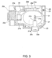
- Fig. 3 is a sectional view showing a lateral view of a pressure buffer 21 inside case 20. Note that Fig. 3 comprises two different y-z sectional planes in the upper and lower part, respectively. Lines III-III in Figs. 1 and 4 illustrate the sectional planes of Fig. 3. Fig. 4 is a sectional view on an x-z plane at the position of line IV-IV in Fig. 1. Fig. 5 is a sectional view along line V-V in Fig. 4.
- Case 20 comprises a main case 20a and a cover 20d.
- Each pressure buffer 21 has a thin platelike main body of a basically elliptical shape in the lateral view of Fig. 3.
- a cavity is formed inside the main body between a first and a second basically elliptical side wall and a peripheral wall.
- the second side wall (the one on the back side, not visible in Fig. 3) is formed by a thin flexible film.
- the cavity thus, constitutes a chamber 21a for absorbing or compensating ink pressure variations.
- a pipe coupling, to which the respective ink tube 23 is connected, is formed on an extension 21b at one longitudinal end (left end in Fig. 3) of the main body.
- Ink is supplied through ink tube 23 to chamber 21a via a channel connecting the pipe coupling with the chamber 21a.
- An outlet portion 22 is formed on the outside of the first side wall and extends below the lower end of the main body.
- a lower tubular part of the outlet portion 22 extends partly from the peripheral wall of the main body and forms an ink outlet 22a; it is designed to fit into the respective tubular extension 20c at the bottom of main case 20a.
- the chamber 21a communicates with the ink outlet 22a, through which ink inside chamber 21a is supplied to inkjet head 12.
- the upper end of the ink outlet portion 22 (the upper end as seen in Fig. 3) forms a spring seat 21c for a coil spring 31.
- a pin 21d for guiding the spring 31 projects from seat 21c; one end of spring 31 fits over the pin 21d.
- Another guide pin 21e is formed on the top of the main body of each pressure buffer 21. This guide pin 21e is exposed to the outside of case 20 through a long hole 20e formed in cover 20d of case 20.
- ink outlet 22a is connected to ink inlet 14 of inkjet head 12, the user depresses this guide pin 21e, which fits into long hole 20e and thereby helps assure a reliable connection.
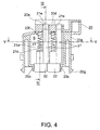
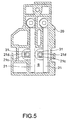
- Each pressure buffer 21 is contained in a housing space S formed inside case 20 between main case 20a and cover 20d. As shown in Fig. 5, housing space S limits the lateral movement of the pressure buffer 21 accommodated therein. As shown in Fig. 3 and Fig. 4, there is also a space above each pressure buffer 21 when it is housed in housing space S, thereby allowing the pressure buffer 21 to move vertically within the housing space S.
- the spring 31 for each pressure buffer 21 is also contained in the housing space S.
- Spring 31 urges the pressure buffer 21 downward, which as noted above, can move up and down within the housing space S.
- Spring 31 is disposed between pin 21d formed on spring seat 21c, and a pin 20f projecting down from cover 20d as is best shown in Fig. 4.
- spring 31 pushes pressure buffer 21 against the inner side of the bottom wall of the main case 20a.
- pressure buffer 21 is lifted slightly in resistance to the force of spring 31, thus forming a slight gap to the inner side of the bottom wall of the main case (see Fig. 3).
- a complete, positive connection is assured between the ink inlet 14 of the inkjet head and the ink outlet 22 of the pressure buffer as more fully described below, and this connection is maintained by the force of spring 31.
- ink tube 23 is connected to the pipe coupling on the extension 21b at one longitudinal end of pressure buffer 21.
- pressure buffer 21 connects to inkjet head 12
- force acts from below on the ink outlet 22, which is disposed toward the opposite longitudinal end of pressure buffer 21, to push pressure buffer 21 upward.
- the connected ink tube 23 applies an opposing force to the pipe coupling resisting the upward movement of pressure buffer 21.
- long hole 20e in case 20 is sized to prevent contact with the guide pin 21e when it moves.
- ink outlet 22 of pressure buffer 21 is a tubular member having a passage 22a formed therein that communicates with chamber 21a.
- Passage 22a has a smaller diameter section 22a' toward chamber 21a and a larger diameter section 22a" toward the outlet opening.
- a shoulder 22b is formed at the transition between sections 22a' and 22a".
- a rubber 0-ring 24 is held against this shoulder 22b by a retainer 25 provided to hold 0-ring 24 in position.
- 0-ring 24 has an inner diameter smaller than that of passage section 22a'.
- an end portion of ink inlet 14 of inkjet head 12 is press fit into section 22a' of passage 22a. More specifically, the outer diameter of ink inlet 14 is slightly smaller than the inner diameter of passage section 22a', and slightly larger than the inner diameter of 0-ring 24. This difference in diameters means that when ink inlet 14 is press fit into the passage 22a, the end portion of ink inlet 14 pushes out on the inside of 0-ring 24, and O-ring 24 forms a tight seal around ink inlet 14.
- pressure buffer 21 is not fixed to case 20, which is fastened to carriage 11, and is pushed, relative to case 20, toward inkjet head 12 by the force of spring 31.
- guide pin 21e on the top of pressure buffer 21 protrudes to the outside of case 20 from long hole 20e formed in cover 20d of case 20.
- the user can therefore push down the guide pin 21e so as to press ink outlet 22 to ink inlet 14 if the connection between pressure buffer 21 and inkjet head 12 established by the force of spring 31 is not sufficient. It is therefore possible to positively press fit ink inlet 14 into ink outlet 22, and thereby assure an even more reliable connection between ink inlet 14 and ink outlet 22.
- the tolerance can be absorbed by movement of the pressure buffers 21 within the case 20, and a reliable connection between inkjet head 12 and pressure buffers 21 can be assured.
- an undesirable external force acts on case 20 when mounted to carriage 11, the effect of such external force is not easily transferred to the pressure buffers 21 because the pressure buffers 21 are not directly fastened to the case. More specifically, such undesirable external force is prevented from propagating to the ink inside the inkjet head, and more particularly to the meniscus formed in the nozzles from which ink droplets are discharged.
- extension 21b for connecting tube 23, ink outlet 22, and guide pin 21e are formed on or immediately next to the circumferential surface of pressure buffer 21 in this preferred embodiment.
- a tube retainer 23a is formed inside the maximum lateral extension of a pressure buffer 21 as viewed in Fig. 4 so that ink tube 23 also extends along the peripheral surface of pressure buffer 21. This makes it possible to house plural pressure buffers 21 side by side in case 20 with the smallest possible gap therebetween, thus helping to downsize the print head unit 10.
- FIG. 6 While an exemplary connecting structure for ink outlet 22 and ink inlet 14 is shown in Fig. 6, the invention is not limited to this structure and other connecting structures will be apparent to one with ordinary skill in the art.
- the present invention has been described with two pressure buffers 21 housed inside case 20, but the invention can be easily adapted for used with a print head unit having only one or three or more pressure buffers.
- our invention makes it possible to reliably and easily connect the ink outlet of a pressure buffer to the ink inlet of a inkjet head in a print head unit regardless of any dimensional tolerance in any of the molded parts.
- the connecting structure of the ink inlet and ink outlet reduces the effect on the pressure buffer of any external force applied to the case in which the pressure buffer is housed. As a result, the effect of such external force on the connection between ink inlet and ink outlet is also reduced.
Abstract
Description
- The present invention relates to a print head unit having an inkjet head, and relates more particularly to a mounting structure for a pressure buffer that avoids pressure variations in the ink inside the inkjet print head.
- Inkjet printers are widely used today as continuing improvements in inkjet head molding technology and ink discharge control technology have made it possible to freely control the placement of minute ink droplets on recording media and achieve extremely high quality printing at high speed.
- The surface condition of the ink nozzles of an inkjet head is extremely important if stable printing results are to be achieved in an inkjet printer; in other words it is necessary that the ink forms an appropriate meniscus in each ink nozzle during printing. To achieve this, the pressure in the path through which ink is supplied to the inkjet head and, within the inkjet head, to the ink nozzles must be kept constant. Ink stored in an ink tank flows through a flexible ink tube to the inkjet head. The inkjet head prints while the print head unit comprising the inkjet head and a carriage is being moved. As a result, the shape of the bend, that is, the curvature, of the ink tube changes as the print head unit moves. This destabilizes the ink pressure in the inkjet head, and creates the danger of the meniscus desirably formed in an ink nozzle being destroyed.
- Some inkjet printers are equipped with a pressure compensator or buffer directly connected to the inkjet head to avoid this problem. The pressure buffer typically has an ink reservoir that freely expands and contracts, and thus has a variable capacity. Ink supplied through the ink tube is temporarily stored in this ink reservoir, and the ink pressure inside the inkjet head is thereby held constant.
- In this type of printer, the inkjet head is normally mounted on a substrate which is secured directly to the carriage. The pressure buffer is fixed inside a particular case, and connection of the pressure buffer to the inkjet head is assured by fastening the case to the carriage.
- In other words, an ink outlet of the pressure buffer is insertion fit onto an ink inlet of the inkjet head when the case is fastened to the carriage, and a seal is thus established between the ink outlet and the ink inlet.
- However, problems such as the following remain in a conventional inkjet printer equipped with a pressure buffer.
- (1) Inevitable molding variations in the case, carriage, and pressure buffer may, even when the case is completely fastened to the carriage, result in the seal between the ink outlet of the pressure buffer and the ink inlet of the inkjet head being not sufficiently tight. More specifically, dimensional tolerance caused by molding variations can create a gap or inclination between the bonding surfaces of the ink inlet and ink outlet, thus degrading the seal.
- (2) External force acting on the case is transferred directly to the pressure buffer inside the case. This can also adversely affect the connection between the ink inlet and ink outlet.
-
- While the ink outlet of the pressure buffer and the ink inlet of the inkjet head could be connected by an adhesive, for instance, to ensure a reliable connection, this would make it more difficult to replace or repair individual parts. It would become particularly difficult to install individual pressure buffers in and remove them from the inkjet head in a print head unit having plural inkjet heads each connected to a respective one of pressure buffers arranged next to one another.
- Furthermore, a pressure buffer must be provided for each of the inks of different colors used in color printers. This increases the size of the print head unit. It is therefore desirable to make the print head unit as small as possible, in particular when plural pressure buffers are present.
- An object of the present invention is to resolve the aforementioned problems of the prior art by providing a print head unit in which the ink outlet of a pressure buffer is reliably connected to the ink inlet of an inkjet head.
- A further object of the present invention is to minimize the effect, on the pressure buffer, of an external force applied to the case, and thus prevent any such external force from affecting the connection between the ink inlet and the ink outlet.
- A yet further object of the present invention is to reduce the size of the print head unit compared to prior art print head units.
- These objects are achieved with a print head unit as claimed in claim 1 and a printer using it as claimed in
claim 10. - According to the invention, the ink outlet can be reliably connected to the ink inlet even if there are molding variations in the support means and/or pressure buffer because the urging means pushes the pressure buffer to the inkjet head.
- Other objects and attainments together with a fuller understanding of the invention will become apparent and appreciated by referring to the following description of preferred embodiments taken in conjunction with the accompanying drawings, in which:
- Fig. 1
- is a perspective view of a print head unit according to an embodiment of the invention;
- Fig. 2
- is a partially exploded perspective view of the print head unit shown in Fig. 1;
- Fig. 3
- is a vertical longitudinal sectional view of the buffer unit;
- Fig. 4
- is a vertical cross-sectional view of the buffer unit;
- Fig. 5
- is a horizontal sectional view of the buffer unit;
- Fig. 6
- is an enlarged sectional view of the connection between the inkjet head and a pressure buffer; and
- Fig. 7
- is perspective view of a printer equipped with the print head unit shown in Fig. 1.
- Referring first to Fig. 7, a printer 1 according to this preferred embodiment has a
roller 125 for transporting paper drawn off apaper roll 100 held in apaper housing 111. The printing medium used in printer 1 is not critical to the present invention and paper is to be understood only as a representative of a variety of printing media that could be employed instead. Drive power from a paper transport motor (not shown in the figure) is transferred via agear 124 toroller 125. An inkjet head 12 (shown in Fig. 2) is disposed above the paper with its ink nozzles facing down so that it can print on the surface of the paper asroller 125 advances the paper toward apaper exit 106. - Printer 1 of the present embodiment is a two-color printer. Thus, the nozzle surface of
print head 12 has two nozzle areas for discharging ink of two different colors, such as red and black. The number of colors is not critical to the present inventions, i.e., the principle of the invention is applicable to single-color printers as well as multi-color printers. - The
inkjet head 12 is supported on acarriage 11, which is arranged to reciprocate, guided by a guide rail orbar 114, in the widthwise direction of the printer. Thecarriage 11 is connected to atiming belt 117 extending in parallel to theguide rail 114. Thetiming belt 117 is driven by acarriage motor 118. Anautomatic paper cutter 126 is disposed directly abovepaper exit 106 for automatically cutting the paper to a specific length after printing is completed. - An
ink buffer unit 19 is also mounted oncarriage 11. Carriage 11,inkjet head 12 andink buffer unit 19 are together referred to asprint head unit 10 in this text. - Two kinds of ink of different colors are supplied, each by means of a respective
flexible ink tube 23, from anink cartridge 121 to a respective one of two pressure buffers 21 (shown in Figs. 3 to 5) contained inink buffer unit 19. Theink cartridge 121 is removably mounted on acartridge holder 120 and contains two ink bags (not shown in the figure) for storing the two kinds of ink. The ink from thepressure buffers 21 is in turn supplied to theinkjet head 12. As will be appreciated by those skilled in the art, the number of ink tubes, pressure buffers and ink bags depends on the number of colors the printer is capable of printing. - The
inkjet head 12 is mounted on a printedcircuit board 13 as best shown in Fig. 2. Printedcircuit board 13 is secured with screws, for example, inside a recess or opening 11a ofcarriage 11. When theinkjet head 12 is fastened tocarriage 11, the nozzle surface of the head is exposed from the bottom ofcarriage 11. In the case of this two-color printer,inkjet head 12 has twotubular ink inlets 14, one for each color, disposed on the rear side of theinkjet head 12, i.e., the side opposite the nozzle surface. Anink outlet 22a of a respective one of the twopressure buffers 21 inbuffer unit 19 is connected to eachink inlet 14. Ink stored in the ink bags is thus supplied to the corresponding nozzle area ofinkjet head 12 by way of theink tubes 23 and pressure buffers 21. - Referring to Figs. 1 and 2,
buffer unit 19 has acase 20 that houses the twopressure buffers 21, and holds them at the top ofcarriage 11 connected toinkjet head 12. A pair ofclaws 20g is provided on two opposite sides ofcase 20. Theclaws 20g engagemating holes 11b formed in the corresponding ones of the side walls defining theopening 11a ofcarriage 11. A through-hole 20b for a screw is formed in a rear part ofcase 20 to extend substantially in parallel to theclaws 20g. Ascrew 30 is inserted into the through-hole 20b and threaded into amating screw hole 11c formed at a corresponding position in the rear part ofcarriage 11 to fastencase 20 tocarriage 11. Instead of theholes 11b corresponding holes could alternatively be provided in the inkjet head and theclaws 20g made to engage the holes in the inkjet head. - As shown in Fig. 2, the
ink outlets 22a of the twopressure buffers 21 are exposed at the bottom ofcase 20 ofbuffer unit 19. That is, holes surrounded bytubular extensions 20c are formed in the bottom ofcase 20, and the ends ofink outlets 22a extend through the holes and are exposed to the outside while being guided by theextensions 20c. Whencase 20 is fastened tocarriage 11, eachink outlet 22a is thus connected to the correspondingink inlet 14 ofinkjet head 12. - The support structure of pressure buffers 21 in
case 20 is described below with reference to Fig. 3 to Fig. 5. Fig. 3 is a sectional view showing a lateral view of apressure buffer 21 insidecase 20. Note that Fig. 3 comprises two different y-z sectional planes in the upper and lower part, respectively. Lines III-III in Figs. 1 and 4 illustrate the sectional planes of Fig. 3. Fig. 4 is a sectional view on an x-z plane at the position of line IV-IV in Fig. 1. Fig. 5 is a sectional view along line V-V in Fig. 4. -
Case 20 comprises amain case 20a and acover 20d. Eachpressure buffer 21 has a thin platelike main body of a basically elliptical shape in the lateral view of Fig. 3. A cavity is formed inside the main body between a first and a second basically elliptical side wall and a peripheral wall. The second side wall (the one on the back side, not visible in Fig. 3) is formed by a thin flexible film. The cavity, thus, constitutes achamber 21a for absorbing or compensating ink pressure variations. A pipe coupling, to which therespective ink tube 23 is connected, is formed on anextension 21b at one longitudinal end (left end in Fig. 3) of the main body. Ink is supplied throughink tube 23 tochamber 21a via a channel connecting the pipe coupling with thechamber 21a. Anoutlet portion 22 is formed on the outside of the first side wall and extends below the lower end of the main body. A lower tubular part of theoutlet portion 22 extends partly from the peripheral wall of the main body and forms anink outlet 22a; it is designed to fit into the respectivetubular extension 20c at the bottom ofmain case 20a. Thechamber 21a communicates with theink outlet 22a, through which ink insidechamber 21a is supplied toinkjet head 12. The upper end of the ink outlet portion 22 (the upper end as seen in Fig. 3) forms aspring seat 21c for acoil spring 31. Apin 21d for guiding thespring 31 projects fromseat 21c; one end ofspring 31 fits over thepin 21d. - Another
guide pin 21e is formed on the top of the main body of eachpressure buffer 21. Thisguide pin 21e is exposed to the outside ofcase 20 through along hole 20e formed incover 20d ofcase 20. Whenink outlet 22a is connected toink inlet 14 ofinkjet head 12, the user depresses thisguide pin 21e, which fits intolong hole 20e and thereby helps assure a reliable connection. - Each
pressure buffer 21 is contained in a housing space S formed insidecase 20 betweenmain case 20a and cover 20d. As shown in Fig. 5, housing space S limits the lateral movement of thepressure buffer 21 accommodated therein. As shown in Fig. 3 and Fig. 4, there is also a space above eachpressure buffer 21 when it is housed in housing space S, thereby allowing thepressure buffer 21 to move vertically within the housing space S. - The
spring 31 for eachpressure buffer 21 is also contained in the housingspace S. Spring 31 urges thepressure buffer 21 downward, which as noted above, can move up and down within the housingspace S. Spring 31 is disposed betweenpin 21d formed onspring seat 21c, and apin 20f projecting down fromcover 20d as is best shown in Fig. 4. Beforecase 20 is mounted oncarriage 11,spring 31 pushes pressurebuffer 21 against the inner side of the bottom wall of themain case 20a. Oncecase 20 is fixed tocarriage 11,pressure buffer 21 is lifted slightly in resistance to the force ofspring 31, thus forming a slight gap to the inner side of the bottom wall of the main case (see Fig. 3). Thus positioned, a complete, positive connection is assured between theink inlet 14 of the inkjet head and theink outlet 22 of the pressure buffer as more fully described below, and this connection is maintained by the force ofspring 31. - It should be noted that, in this exemplary embodiment,
ink tube 23 is connected to the pipe coupling on theextension 21b at one longitudinal end ofpressure buffer 21. Whenpressure buffer 21 connects toinkjet head 12, force acts from below on theink outlet 22, which is disposed toward the opposite longitudinal end ofpressure buffer 21, to pushpressure buffer 21 upward. At the same time, theconnected ink tube 23 applies an opposing force to the pipe coupling resisting the upward movement ofpressure buffer 21. These opposite forces acting at two longitudinally spaced portions ofpressure buffer 21 apply a counterclockwise moment to thepressure buffer 21 as viewed in Fig. 3. - Note that while
guide pin 21e moves slightly to the left at this time,long hole 20e incase 20 is sized to prevent contact with theguide pin 21e when it moves. - A connecting structure for the
inkjet head 12 andpressure buffer 21 is described next. This connecting structure is shown in section in Fig. 6. As shown in Fig. 6,ink outlet 22 ofpressure buffer 21 is a tubular member having apassage 22a formed therein that communicates withchamber 21a.Passage 22a has asmaller diameter section 22a' towardchamber 21a and alarger diameter section 22a" toward the outlet opening. Ashoulder 22b is formed at the transition betweensections 22a' and 22a". A rubber 0-ring 24 is held against thisshoulder 22b by aretainer 25 provided to hold 0-ring 24 in position. 0-ring 24 has an inner diameter smaller than that ofpassage section 22a'. As shown in this figure, an end portion ofink inlet 14 ofinkjet head 12 is press fit intosection 22a' ofpassage 22a. More specifically, the outer diameter ofink inlet 14 is slightly smaller than the inner diameter ofpassage section 22a', and slightly larger than the inner diameter of 0-ring 24. This difference in diameters means that whenink inlet 14 is press fit into thepassage 22a, the end portion ofink inlet 14 pushes out on the inside of 0-ring 24, and O-ring 24 forms a tight seal aroundink inlet 14. - The action of the present invention is described next in conjunction with the procedure for connecting
pressure buffer 21 toinkjet head 12 according to this preferred embodiment. Connectingpressure buffer 21 toinkjet head 12 is accomplished by fixingcase 20 tocarriage 11 as noted above. Each of the pressure buffers 21 is thus urged downward insidecase 20 by the correspondingspring 31. Held as shown in Fig. 2,case 20 is positioned tocarriage 11, and theclaws 20g are then engaged withholes 11b ofcarriage 11.Screw 30 is then passed through through-hole 20b incase 20 and screwed intoscrew hole 11c incarriage 11, thereby fasteningcase 20 tocarriage 11. Thus assembled,ink inlet 14 ofinkjet head 12 is press fit intoink outlet 22 ofpressure buffer 21 as shown in Fig. 6, andink inlet 14 andink outlet 22 are thus reliably connected. It should be noted that at thistime pressure buffer 21 is not fixed tocase 20, which is fastened tocarriage 11, and is pushed, relative tocase 20, towardinkjet head 12 by the force ofspring 31. - As shown in Fig. 3 and Fig. 4,
guide pin 21e on the top ofpressure buffer 21 protrudes to the outside ofcase 20 fromlong hole 20e formed incover 20d ofcase 20. The user can therefore push down theguide pin 21e so as to pressink outlet 22 toink inlet 14 if the connection betweenpressure buffer 21 andinkjet head 12 established by the force ofspring 31 is not sufficient. It is therefore possible to positively pressfit ink inlet 14 intoink outlet 22, and thereby assure an even more reliable connection betweenink inlet 14 andink outlet 22. - If the dimensional tolerance is relatively large when these components are molded, and the mounting height of the
case 20 to thecarriage 11 thus varies, the tolerance can be absorbed by movement of the pressure buffers 21 within thecase 20, and a reliable connection betweeninkjet head 12 and pressure buffers 21 can be assured. Furthermore, if an undesirable external force acts oncase 20 when mounted tocarriage 11, the effect of such external force is not easily transferred to the pressure buffers 21 because the pressure buffers 21 are not directly fastened to the case. More specifically, such undesirable external force is prevented from propagating to the ink inside the inkjet head, and more particularly to the meniscus formed in the nozzles from which ink droplets are discharged. - Furthermore, force greatly exceeding the urging force of
springs 31 is not applied to the connection betweeninkjet head 12 and pressure buffers 21 whencase 20 is mounted oncarriage 11, and damage to said connection can thus be prevented. - Yet further,
extension 21b for connectingtube 23,ink outlet 22, and guidepin 21e are formed on or immediately next to the circumferential surface ofpressure buffer 21 in this preferred embodiment. In addition, atube retainer 23a is formed inside the maximum lateral extension of apressure buffer 21 as viewed in Fig. 4 so thatink tube 23 also extends along the peripheral surface ofpressure buffer 21. This makes it possible to house plural pressure buffers 21 side by side incase 20 with the smallest possible gap therebetween, thus helping to downsize theprint head unit 10. - Although the present invention has been described in connection with preferred embodiments thereof with reference to the accompanying drawings, it is to be noted that various changes and modifications will be apparent to those skilled in the art. For example, while a
coil spring 31 is used to pushpressure buffer 21 against theinkjet head 12 in the present embodiment, various other types of urging means, such as a leaf spring, can be alternatively used. - Furthermore, while an exemplary connecting structure for
ink outlet 22 andink inlet 14 is shown in Fig. 6, the invention is not limited to this structure and other connecting structures will be apparent to one with ordinary skill in the art. - Yet further, the present invention has been described with two
pressure buffers 21 housed insidecase 20, but the invention can be easily adapted for used with a print head unit having only one or three or more pressure buffers. - As described above, our invention makes it possible to reliably and easily connect the ink outlet of a pressure buffer to the ink inlet of a inkjet head in a print head unit regardless of any dimensional tolerance in any of the molded parts.
- Furthermore, the connecting structure of the ink inlet and ink outlet reduces the effect on the pressure buffer of any external force applied to the case in which the pressure buffer is housed. As a result, the effect of such external force on the connection between ink inlet and ink outlet is also reduced.
Claims (10)
- A print head unit comprising:an inkjet head (12) having an ink inlet (14) and being secured to first support means (11);ink supply means (19, 23) for supplying ink to said ink inlet (14), the ink supply means (19, 23) including a pressure buffer (21) for avoiding the ink supplied to said ink inlet (14) from being subjected to pressure variations, the pressure buffer (21) having an ink outlet (22a) detachably connected to said ink inlet (14), such that it can be detached by relative movement with respect to the ink inlet (14) in a first direction and connected by relative movement in the opposite second direction;second support means (20) for supporting the pressure buffer (21) so as to be movable in said first and second directions, said second support means (20) being detachably fixed to the first support means (11); andurging means (31) for pushing the ink outlet (22a) of the pressure buffer (21) in said second direction to the ink inlet (14) of the inkjet head (12).
- The print head unit of claim 1, wherein the pressure buffer (21) has a seat (21c) formed on a side of the ink outlet (22a) opposite to the side connected to said ink inlet (14), and the urging means (31) pushes against said seat (21c).
- The print head unit of claim 1 or 2, wherein said second support means (20) is a case accommodating said pressure buffer (21) therein and the urging means (31) is a spring arranged between said seat (21c) and an inner wall of the case.
- The print head unit of any one of claims 1 to 3, wherein said second support means (20) comprises guide means (20c) for limiting a movement of the pressure buffer (21) in a direction other than said first and second directions.
- The print head unit of any of claims 1 to 4, wherein said second support means (20) is a case accommodating said pressure buffer (21) therein, an opening for exposing said ink outlet (22a) being provided in a bottom wall of the case, and
an opening (20e) for exposing part (21e) of a top of the pressure buffer (21) is disposed in a top wall of the case. - The print head unit of claim 5, wherein the pressure buffer (21) further comprises a pin (21e) penetrating said opening (20e) and projecting to the outside of said case.
- The print head unit of claim 6, wherein the pressure buffer (21) has a circumferential surface between two substantially parallel side walls, and the ink inlet (14), ink outlet (22a), and pin (21e) are formed on said circumferential surface.
- The print head unit of any of claims 1 to 7, wherein the first support means (11) holds a plurality of inkjet heads (12), and
the second support means (20) houses a plurality of pressure buffers (21) each corresponding to one of the inkjet heads (12). - The print head unit of any of claims 1 to 8, wherein the first support means (11) is a carriage.
- A printer comprising the print head unit (10) of any one of claims 1 to 9.
Applications Claiming Priority (4)
| Application Number | Priority Date | Filing Date | Title |
|---|---|---|---|
| JP2000017616A JP4456711B2 (en) | 2000-01-26 | 2000-01-26 | Print head unit |
| JP2000017615 | 2000-01-26 | ||
| JP2000017616 | 2000-01-26 | ||
| JP2000017615 | 2000-01-26 |
Publications (3)
| Publication Number | Publication Date |
|---|---|
| EP1120257A2 true EP1120257A2 (en) | 2001-08-01 |
| EP1120257A3 EP1120257A3 (en) | 2002-01-16 |
| EP1120257B1 EP1120257B1 (en) | 2003-05-02 |
Family
ID=26584212
Family Applications (1)
| Application Number | Title | Priority Date | Filing Date |
|---|---|---|---|
| EP00127300A Expired - Lifetime EP1120257B1 (en) | 2000-01-26 | 2000-12-20 | Print head unit |
Country Status (8)
| Country | Link |
|---|---|
| US (1) | US6460986B2 (en) |
| EP (1) | EP1120257B1 (en) |
| KR (1) | KR100510310B1 (en) |
| CN (1) | CN1145555C (en) |
| AT (1) | ATE238910T1 (en) |
| DE (1) | DE60002423T2 (en) |
| ES (1) | ES2193917T3 (en) |
| HK (1) | HK1040964B (en) |
Cited By (4)
| Publication number | Priority date | Publication date | Assignee | Title |
|---|---|---|---|---|
| WO2006116963A2 (en) * | 2005-04-29 | 2006-11-09 | Buestgens Burkhard | Ink supply for printing heads |
| US7901063B2 (en) | 2004-12-17 | 2011-03-08 | Agfa Graphics Nv | Ink rejuvenation system for inkjet printing |
| WO2012130981A1 (en) | 2011-03-31 | 2012-10-04 | Arkema France | Method for producing an object having a printed three-dimensional surface |
| US8500244B2 (en) | 2006-03-03 | 2013-08-06 | Zamtec Ltd | Printhead support structure with cavities for pulse damping |
Families Citing this family (15)
| Publication number | Priority date | Publication date | Assignee | Title |
|---|---|---|---|---|
| US7210771B2 (en) * | 2004-01-08 | 2007-05-01 | Eastman Kodak Company | Ink delivery system with print cartridge, container and reservoir apparatus and method |
| US7364261B2 (en) * | 2004-03-10 | 2008-04-29 | Lexmark International, Inc. | Directionally dependent carrier isolator for an imaging apparatus |
| US7721441B2 (en) * | 2006-03-03 | 2010-05-25 | Silverbrook Research Pty Ltd | Method of fabricating a printhead integrated circuit attachment film |
| US7475976B2 (en) * | 2006-03-03 | 2009-01-13 | Silverbrook Research Pty Ltd | Printhead with elongate array of nozzles and distributed pulse dampers |
| CN101287606B (en) * | 2006-03-03 | 2010-11-03 | 西尔弗布鲁克研究有限公司 | Pulse damped fluidic architecture |
| WO2008113094A1 (en) * | 2007-03-21 | 2008-09-25 | Silverbrook Research Pty Ltd | Fluidically damped printhead |
| US7758177B2 (en) * | 2007-03-21 | 2010-07-20 | Silverbrook Research Pty Ltd | High flowrate filter for inkjet printhead |
| US7654640B2 (en) * | 2007-03-21 | 2010-02-02 | Silverbrook Research Pty Ltd | Printhead with drive circuitry components adjacent the printhead IC |
| US20080231660A1 (en) * | 2007-03-21 | 2008-09-25 | Silverbrook Research Pty Ltd | Printhead with ink conduit weir for priming control |
| US8523143B2 (en) * | 2007-03-21 | 2013-09-03 | Zamtec Ltd | Detachable fluid coupling for inkjet printer |
| US7819507B2 (en) * | 2007-03-21 | 2010-10-26 | Silverbrook Research Pty Ltd | Printhead with meniscus anchor for controlled priming |
| US7364265B1 (en) * | 2007-03-21 | 2008-04-29 | Silverbrook Research Pty Ltd | Printhead with enhanced ink supply to elongate printhead IC ends |
| US7780278B2 (en) * | 2007-03-21 | 2010-08-24 | Silverbrook Research Pty Ltd | Ink coupling for inkjet printer with cartridge |
| ITVI20120276A1 (en) | 2012-10-19 | 2014-04-20 | New System Srl | COMPENSATION DEVICE FOR A PRINT HEAD AND PRINT GROUP INCLUDING SUCH COMPENSATION DEVICE |
| JP6578740B2 (en) * | 2015-05-24 | 2019-09-25 | 株式会社リコー | Device for discharging liquid |
Citations (13)
| Publication number | Priority date | Publication date | Assignee | Title |
|---|---|---|---|---|
| JPH02150354A (en) * | 1988-12-01 | 1990-06-08 | Seiko Epson Corp | Ink jet recording head |
| EP0496620A1 (en) * | 1991-01-25 | 1992-07-29 | Canon Kabushiki Kaisha | Ink jet recording apparatus and ink jet cartridge usable therewith |
| JPH06210864A (en) * | 1993-01-19 | 1994-08-02 | Canon Inc | Ink jet recording head, ink jet head cartridge and recording apparatus having the recording head |
| EP0779157A2 (en) * | 1992-07-31 | 1997-06-18 | Canon Kabushiki Kaisha | Liquid storing container for recording apparatus |
| JPH10128999A (en) * | 1996-10-30 | 1998-05-19 | Canon Inc | Ink jet apparatus |
| DE19748914A1 (en) * | 1997-01-30 | 1998-08-13 | Hewlett Packard Co | Electrical and fluidic interface for an ink supply |
| JPH10329340A (en) * | 1997-05-29 | 1998-12-15 | Seiko Epson Corp | Carriage cover for ink jet color printer |
| EP0891866A2 (en) * | 1997-07-14 | 1999-01-20 | Owens-Illinois Closure Inc. | Liquid containment and dispensing device with improved flow control valve |
| US5877794A (en) * | 1993-03-09 | 1999-03-02 | Fuji Xerox Co., Ltd. | Method for supplying ink to an ink jet recording device |
| JPH1170666A (en) * | 1997-08-29 | 1999-03-16 | Seiko Epson Corp | Ink-jet recording apparatus |
| DE19904804A1 (en) * | 1998-02-06 | 1999-08-12 | Michael Nothelfer | Ink supply arrangement for black and white or color printer, plotter or similar |
| US5971529A (en) * | 1994-10-31 | 1999-10-26 | Hewlett-Packard Company | Automatic ink interconnect between print cartridge and carriage |
| US6017118A (en) * | 1995-04-27 | 2000-01-25 | Hewlett-Packard Company | High performance ink container with efficient construction |
Family Cites Families (4)
| Publication number | Priority date | Publication date | Assignee | Title |
|---|---|---|---|---|
| CA2009631C (en) * | 1989-02-17 | 1994-09-20 | Shigeo Nonoyama | Pressure damper of an ink jet printer |
| JPH05201016A (en) * | 1992-01-28 | 1993-08-10 | Seiko Epson Corp | Ink jet recording head and method for connecting ink jet recording head and pressure damper |
| JPH10193646A (en) * | 1997-01-09 | 1998-07-28 | Seiko Epson Corp | Print head unit, ink jet printer having the same, and ink cartridge |
| US5992992A (en) * | 1998-06-11 | 1999-11-30 | Lexmark International, Inc. | Pressure control device for an ink jet printer |
-
2000
- 2000-12-20 DE DE60002423T patent/DE60002423T2/en not_active Expired - Lifetime
- 2000-12-20 EP EP00127300A patent/EP1120257B1/en not_active Expired - Lifetime
- 2000-12-20 AT AT00127300T patent/ATE238910T1/en not_active IP Right Cessation
- 2000-12-20 ES ES00127300T patent/ES2193917T3/en not_active Expired - Lifetime
- 2000-12-21 US US09/745,956 patent/US6460986B2/en not_active Expired - Lifetime
-
2001
- 2001-01-20 KR KR10-2001-0003373A patent/KR100510310B1/en not_active IP Right Cessation
- 2001-01-23 CN CNB011196521A patent/CN1145555C/en not_active Expired - Fee Related
-
2002
- 2002-04-17 HK HK02102916.5A patent/HK1040964B/en not_active IP Right Cessation
Patent Citations (13)
| Publication number | Priority date | Publication date | Assignee | Title |
|---|---|---|---|---|
| JPH02150354A (en) * | 1988-12-01 | 1990-06-08 | Seiko Epson Corp | Ink jet recording head |
| EP0496620A1 (en) * | 1991-01-25 | 1992-07-29 | Canon Kabushiki Kaisha | Ink jet recording apparatus and ink jet cartridge usable therewith |
| EP0779157A2 (en) * | 1992-07-31 | 1997-06-18 | Canon Kabushiki Kaisha | Liquid storing container for recording apparatus |
| JPH06210864A (en) * | 1993-01-19 | 1994-08-02 | Canon Inc | Ink jet recording head, ink jet head cartridge and recording apparatus having the recording head |
| US5877794A (en) * | 1993-03-09 | 1999-03-02 | Fuji Xerox Co., Ltd. | Method for supplying ink to an ink jet recording device |
| US5971529A (en) * | 1994-10-31 | 1999-10-26 | Hewlett-Packard Company | Automatic ink interconnect between print cartridge and carriage |
| US6017118A (en) * | 1995-04-27 | 2000-01-25 | Hewlett-Packard Company | High performance ink container with efficient construction |
| JPH10128999A (en) * | 1996-10-30 | 1998-05-19 | Canon Inc | Ink jet apparatus |
| DE19748914A1 (en) * | 1997-01-30 | 1998-08-13 | Hewlett Packard Co | Electrical and fluidic interface for an ink supply |
| JPH10329340A (en) * | 1997-05-29 | 1998-12-15 | Seiko Epson Corp | Carriage cover for ink jet color printer |
| EP0891866A2 (en) * | 1997-07-14 | 1999-01-20 | Owens-Illinois Closure Inc. | Liquid containment and dispensing device with improved flow control valve |
| JPH1170666A (en) * | 1997-08-29 | 1999-03-16 | Seiko Epson Corp | Ink-jet recording apparatus |
| DE19904804A1 (en) * | 1998-02-06 | 1999-08-12 | Michael Nothelfer | Ink supply arrangement for black and white or color printer, plotter or similar |
Non-Patent Citations (5)
| Title |
|---|
| PATENT ABSTRACTS OF JAPAN vol. 014, no. 395 (M-1016), 27 August 1990 (1990-08-27) & JP 02 150354 A (SEIKO EPSON CORP), 8 June 1990 (1990-06-08) * |
| PATENT ABSTRACTS OF JAPAN vol. 018, no. 576 (M-1697), 4 November 1994 (1994-11-04) & JP 06 210864 A (CANON INC), 2 August 1994 (1994-08-02) * |
| PATENT ABSTRACTS OF JAPAN vol. 1998, no. 10, 31 August 1998 (1998-08-31) & JP 10 128999 A (CANON INC), 19 May 1998 (1998-05-19) * |
| PATENT ABSTRACTS OF JAPAN vol. 1999, no. 03, 31 March 1999 (1999-03-31) & JP 10 329340 A (SEIKO EPSON CORP), 15 December 1998 (1998-12-15) * |
| PATENT ABSTRACTS OF JAPAN vol. 1999, no. 08, 30 June 1999 (1999-06-30) & JP 11 070666 A (SEIKO EPSON CORP), 16 March 1999 (1999-03-16) * |
Cited By (5)
| Publication number | Priority date | Publication date | Assignee | Title |
|---|---|---|---|---|
| US7901063B2 (en) | 2004-12-17 | 2011-03-08 | Agfa Graphics Nv | Ink rejuvenation system for inkjet printing |
| WO2006116963A2 (en) * | 2005-04-29 | 2006-11-09 | Buestgens Burkhard | Ink supply for printing heads |
| WO2006116963A3 (en) * | 2005-04-29 | 2007-03-15 | Burkhard Buestgens | Ink supply for printing heads |
| US8500244B2 (en) | 2006-03-03 | 2013-08-06 | Zamtec Ltd | Printhead support structure with cavities for pulse damping |
| WO2012130981A1 (en) | 2011-03-31 | 2012-10-04 | Arkema France | Method for producing an object having a printed three-dimensional surface |
Also Published As
| Publication number | Publication date |
|---|---|
| DE60002423T2 (en) | 2004-03-11 |
| HK1040964A1 (en) | 2002-06-28 |
| KR20010078032A (en) | 2001-08-20 |
| ES2193917T3 (en) | 2003-11-16 |
| EP1120257B1 (en) | 2003-05-02 |
| DE60002423D1 (en) | 2003-06-05 |
| EP1120257A3 (en) | 2002-01-16 |
| US6460986B2 (en) | 2002-10-08 |
| US20010009434A1 (en) | 2001-07-26 |
| CN1318472A (en) | 2001-10-24 |
| HK1040964B (en) | 2005-02-18 |
| ATE238910T1 (en) | 2003-05-15 |
| CN1145555C (en) | 2004-04-14 |
| KR100510310B1 (en) | 2005-08-26 |
Similar Documents
| Publication | Publication Date | Title |
|---|---|---|
| EP1120257B1 (en) | Print head unit | |
| US6508547B2 (en) | Replaceable ink container for an inkjet printing system | |
| US6488369B1 (en) | Ink container configured to establish reliable electrical and fluidic connections to a receiving station | |
| US6302535B1 (en) | Ink container configured to establish reliable electrical connection with a receiving station | |
| EP0968090B1 (en) | Ink container having electronic and mechanical features enabling plug compatibility between multiple supply sizes | |
| EP1122078B1 (en) | Replaceable ink container for an inkjet printing system | |
| US6375315B1 (en) | Replaceable ink container for an inkjet printing system | |
| CA2394696C (en) | Latch and handle arrangement for a replaceable ink container | |
| US6749292B2 (en) | Replaceable ink container for an inkjet printing system | |
| CA2394719C (en) | Ink container for reliable electrical connection with a receiving station | |
| US8297745B2 (en) | Image forming apparatus | |
| JPH0239945A (en) | Ink cartridge | |
| KR100473960B1 (en) | Ink container configured for use with printer | |
| EP1122077B1 (en) | Replaceable ink container for an inkjet printing system | |
| US6648458B2 (en) | Pinch seal providing fluid interconnects between fluid delivery system components | |
| JP4318053B2 (en) | Ink supply apparatus and inkjet image recording apparatus | |
| US6827432B2 (en) | Replaceable ink container for an inkjet printing system | |
| US20210402804A1 (en) | Image recording apparatus | |
| JP4411787B2 (en) | Print head unit and printer having the same | |
| KR100832590B1 (en) | Ink tank, printing head and inkjet printing apparatus | |
| JP2001205818A (en) | Printing head unit |
Legal Events
| Date | Code | Title | Description |
|---|---|---|---|
| PUAI | Public reference made under article 153(3) epc to a published international application that has entered the european phase |
Free format text: ORIGINAL CODE: 0009012 |
|
| AK | Designated contracting states |
Kind code of ref document: A2 Designated state(s): AT BE CH CY DE DK ES FI FR GB GR IE IT LI LU MC NL PT SE TR |
|
| AX | Request for extension of the european patent |
Free format text: AL;LT;LV;MK;RO;SI |
|
| PUAL | Search report despatched |
Free format text: ORIGINAL CODE: 0009013 |
|
| AK | Designated contracting states |
Kind code of ref document: A3 Designated state(s): AT BE CH CY DE DK ES FI FR GB GR IE IT LI LU MC NL PT SE TR |
|
| AX | Request for extension of the european patent |
Free format text: AL;LT;LV;MK;RO;SI |
|
| 17P | Request for examination filed |
Effective date: 20020306 |
|
| 17Q | First examination report despatched |
Effective date: 20020522 |
|
| GRAH | Despatch of communication of intention to grant a patent |
Free format text: ORIGINAL CODE: EPIDOS IGRA |
|
| AKX | Designation fees paid |
Free format text: AT BE CH CY DE DK ES FI FR GB GR IE IT LI LU MC NL PT SE TR |
|
| GRAH | Despatch of communication of intention to grant a patent |
Free format text: ORIGINAL CODE: EPIDOS IGRA |
|
| GRAA | (expected) grant |
Free format text: ORIGINAL CODE: 0009210 |
|
| AK | Designated contracting states |
Designated state(s): AT BE CH CY DE DK ES FI FR GB GR IE IT LI LU MC NL PT SE TR |
|
| PG25 | Lapsed in a contracting state [announced via postgrant information from national office to epo] |
Ref country code: AT Free format text: LAPSE BECAUSE OF FAILURE TO SUBMIT A TRANSLATION OF THE DESCRIPTION OR TO PAY THE FEE WITHIN THE PRESCRIBED TIME-LIMIT Effective date: 20030502 Ref country code: TR Free format text: LAPSE BECAUSE OF FAILURE TO SUBMIT A TRANSLATION OF THE DESCRIPTION OR TO PAY THE FEE WITHIN THE PRESCRIBED TIME-LIMIT Effective date: 20030502 Ref country code: FI Free format text: LAPSE BECAUSE OF FAILURE TO SUBMIT A TRANSLATION OF THE DESCRIPTION OR TO PAY THE FEE WITHIN THE PRESCRIBED TIME-LIMIT Effective date: 20030502 |
|
| REG | Reference to a national code |
Ref country code: GB Ref legal event code: FG4D |
|
| REG | Reference to a national code |
Ref country code: CH Ref legal event code: EP Ref country code: CH Ref legal event code: NV Representative=s name: E. BLUM & CO. PATENTANWAELTE |
|
| REF | Corresponds to: |
Ref document number: 60002423 Country of ref document: DE Date of ref document: 20030605 Kind code of ref document: P |
|
| REG | Reference to a national code |
Ref country code: IE Ref legal event code: FG4D |
|
| PG25 | Lapsed in a contracting state [announced via postgrant information from national office to epo] |
Ref country code: GR Free format text: LAPSE BECAUSE OF FAILURE TO SUBMIT A TRANSLATION OF THE DESCRIPTION OR TO PAY THE FEE WITHIN THE PRESCRIBED TIME-LIMIT Effective date: 20030802 Ref country code: SE Free format text: LAPSE BECAUSE OF FAILURE TO SUBMIT A TRANSLATION OF THE DESCRIPTION OR TO PAY THE FEE WITHIN THE PRESCRIBED TIME-LIMIT Effective date: 20030802 Ref country code: DK Free format text: LAPSE BECAUSE OF FAILURE TO SUBMIT A TRANSLATION OF THE DESCRIPTION OR TO PAY THE FEE WITHIN THE PRESCRIBED TIME-LIMIT Effective date: 20030802 |
|
| PG25 | Lapsed in a contracting state [announced via postgrant information from national office to epo] |
Ref country code: PT Free format text: LAPSE BECAUSE OF FAILURE TO SUBMIT A TRANSLATION OF THE DESCRIPTION OR TO PAY THE FEE WITHIN THE PRESCRIBED TIME-LIMIT Effective date: 20030804 |
|
| REG | Reference to a national code |
Ref country code: ES Ref legal event code: FG2A Ref document number: 2193917 Country of ref document: ES Kind code of ref document: T3 |
|
| PG25 | Lapsed in a contracting state [announced via postgrant information from national office to epo] |
Ref country code: LU Free format text: LAPSE BECAUSE OF NON-PAYMENT OF DUE FEES Effective date: 20031220 Ref country code: CY Free format text: LAPSE BECAUSE OF FAILURE TO SUBMIT A TRANSLATION OF THE DESCRIPTION OR TO PAY THE FEE WITHIN THE PRESCRIBED TIME-LIMIT Effective date: 20031220 |
|
| PG25 | Lapsed in a contracting state [announced via postgrant information from national office to epo] |
Ref country code: IE Free format text: LAPSE BECAUSE OF NON-PAYMENT OF DUE FEES Effective date: 20031222 |
|
| PG25 | Lapsed in a contracting state [announced via postgrant information from national office to epo] |
Ref country code: MC Free format text: LAPSE BECAUSE OF NON-PAYMENT OF DUE FEES Effective date: 20031231 |
|
| ET | Fr: translation filed | ||
| PLBE | No opposition filed within time limit |
Free format text: ORIGINAL CODE: 0009261 |
|
| STAA | Information on the status of an ep patent application or granted ep patent |
Free format text: STATUS: NO OPPOSITION FILED WITHIN TIME LIMIT |
|
| 26N | No opposition filed |
Effective date: 20040203 |
|
| REG | Reference to a national code |
Ref country code: IE Ref legal event code: MM4A |
|
| REG | Reference to a national code |
Ref country code: CH Ref legal event code: PFA Owner name: SEIKO EPSON CORPORATION Free format text: SEIKO EPSON CORPORATION#4-1, NISHISHINJUKU 2-CHOME#SHINJUKU-KU, TOKYO 163-0811 (JP) -TRANSFER TO- SEIKO EPSON CORPORATION#4-1, NISHISHINJUKU 2-CHOME#SHINJUKU-KU, TOKYO 163-0811 (JP) |
|
| PGFP | Annual fee paid to national office [announced via postgrant information from national office to epo] |
Ref country code: CH Payment date: 20101215 Year of fee payment: 11 |
|
| PGFP | Annual fee paid to national office [announced via postgrant information from national office to epo] |
Ref country code: NL Payment date: 20101220 Year of fee payment: 11 Ref country code: BE Payment date: 20101117 Year of fee payment: 11 |
|
| PGFP | Annual fee paid to national office [announced via postgrant information from national office to epo] |
Ref country code: ES Payment date: 20110112 Year of fee payment: 11 |
|
| BERE | Be: lapsed |
Owner name: *SEIKO EPSON CORP. Effective date: 20111231 |
|
| REG | Reference to a national code |
Ref country code: NL Ref legal event code: V1 Effective date: 20120701 |
|
| REG | Reference to a national code |
Ref country code: CH Ref legal event code: PL |
|
| PG25 | Lapsed in a contracting state [announced via postgrant information from national office to epo] |
Ref country code: BE Free format text: LAPSE BECAUSE OF NON-PAYMENT OF DUE FEES Effective date: 20111231 Ref country code: CH Free format text: LAPSE BECAUSE OF NON-PAYMENT OF DUE FEES Effective date: 20111231 Ref country code: LI Free format text: LAPSE BECAUSE OF NON-PAYMENT OF DUE FEES Effective date: 20111231 |
|
| PG25 | Lapsed in a contracting state [announced via postgrant information from national office to epo] |
Ref country code: NL Free format text: LAPSE BECAUSE OF NON-PAYMENT OF DUE FEES Effective date: 20120701 |
|
| REG | Reference to a national code |
Ref country code: ES Ref legal event code: FD2A Effective date: 20130704 |
|
| PG25 | Lapsed in a contracting state [announced via postgrant information from national office to epo] |
Ref country code: ES Free format text: LAPSE BECAUSE OF NON-PAYMENT OF DUE FEES Effective date: 20111221 |
|
| PGFP | Annual fee paid to national office [announced via postgrant information from national office to epo] |
Ref country code: GB Payment date: 20141217 Year of fee payment: 15 Ref country code: DE Payment date: 20141216 Year of fee payment: 15 |
|
| PGFP | Annual fee paid to national office [announced via postgrant information from national office to epo] |
Ref country code: FR Payment date: 20141208 Year of fee payment: 15 |
|
| PGFP | Annual fee paid to national office [announced via postgrant information from national office to epo] |
Ref country code: IT Payment date: 20141127 Year of fee payment: 15 |
|
| REG | Reference to a national code |
Ref country code: DE Ref legal event code: R119 Ref document number: 60002423 Country of ref document: DE |
|
| GBPC | Gb: european patent ceased through non-payment of renewal fee |
Effective date: 20151220 |
|
| REG | Reference to a national code |
Ref country code: FR Ref legal event code: ST Effective date: 20160831 |
|
| PG25 | Lapsed in a contracting state [announced via postgrant information from national office to epo] |
Ref country code: GB Free format text: LAPSE BECAUSE OF NON-PAYMENT OF DUE FEES Effective date: 20151220 Ref country code: DE Free format text: LAPSE BECAUSE OF NON-PAYMENT OF DUE FEES Effective date: 20160701 |
|
| PG25 | Lapsed in a contracting state [announced via postgrant information from national office to epo] |
Ref country code: FR Free format text: LAPSE BECAUSE OF NON-PAYMENT OF DUE FEES Effective date: 20151231 |
|
| PG25 | Lapsed in a contracting state [announced via postgrant information from national office to epo] |
Ref country code: IT Free format text: LAPSE BECAUSE OF NON-PAYMENT OF DUE FEES Effective date: 20151220 |