US20030197650A1 - Layout for automotive window antenna - Google Patents
Layout for automotive window antenna Download PDFInfo
- Publication number
- US20030197650A1 US20030197650A1 US10/127,915 US12791502A US2003197650A1 US 20030197650 A1 US20030197650 A1 US 20030197650A1 US 12791502 A US12791502 A US 12791502A US 2003197650 A1 US2003197650 A1 US 2003197650A1
- Authority
- US
- United States
- Prior art keywords
- wire
- antenna
- layout
- array
- pattern layout
- Prior art date
- Legal status (The legal status is an assumption and is not a legal conclusion. Google has not performed a legal analysis and makes no representation as to the accuracy of the status listed.)
- Granted
Links
- 238000004891 communication Methods 0.000 claims abstract description 51
- 230000008859 change Effects 0.000 claims abstract description 13
- 238000010438 heat treatment Methods 0.000 claims abstract description 11
- 230000001413 cellular effect Effects 0.000 claims abstract description 4
- 230000008878 coupling Effects 0.000 claims description 16
- 238000010168 coupling process Methods 0.000 claims description 16
- 238000005859 coupling reaction Methods 0.000 claims description 16
- 239000003989 dielectric material Substances 0.000 claims description 15
- 239000011521 glass Substances 0.000 claims description 12
- 239000004033 plastic Substances 0.000 claims description 10
- 229920003023 plastic Polymers 0.000 claims description 10
- 239000004417 polycarbonate Substances 0.000 claims description 4
- 229920000515 polycarbonate Polymers 0.000 claims description 4
- VVQNEPGJFQJSBK-UHFFFAOYSA-N Methyl methacrylate Chemical compound COC(=O)C(C)=C VVQNEPGJFQJSBK-UHFFFAOYSA-N 0.000 claims description 3
- 229920005372 Plexiglas® Polymers 0.000 claims description 3
- 239000011152 fibreglass Substances 0.000 claims description 3
- 239000005336 safety glass Substances 0.000 claims description 3
- 238000013461 design Methods 0.000 abstract description 8
- 238000012360 testing method Methods 0.000 description 21
- 238000010586 diagram Methods 0.000 description 20
- 239000004020 conductor Substances 0.000 description 4
- 238000003491 array Methods 0.000 description 3
- 239000002184 metal Substances 0.000 description 3
- 238000012986 modification Methods 0.000 description 2
- 230000004048 modification Effects 0.000 description 2
- 230000005540 biological transmission Effects 0.000 description 1
- -1 but not limited to Substances 0.000 description 1
- 230000001419 dependent effect Effects 0.000 description 1
- 230000005611 electricity Effects 0.000 description 1
- 238000001125 extrusion Methods 0.000 description 1
- 230000006872 improvement Effects 0.000 description 1
- 238000004519 manufacturing process Methods 0.000 description 1
- 238000000034 method Methods 0.000 description 1
- 230000005855 radiation Effects 0.000 description 1
- 238000010257 thawing Methods 0.000 description 1
- 238000001771 vacuum deposition Methods 0.000 description 1
Images


Classifications
-
- H—ELECTRICITY
- H01—ELECTRIC ELEMENTS
- H01Q—ANTENNAS, i.e. RADIO AERIALS
- H01Q1/00—Details of, or arrangements associated with, antennas
- H01Q1/12—Supports; Mounting means
- H01Q1/1271—Supports; Mounting means for mounting on windscreens
- H01Q1/1278—Supports; Mounting means for mounting on windscreens in association with heating wires or layers
Definitions
- the present invention relates generally to a layout for an antenna. More particularly, the present invention relates primarily to a layout for a radio frequency (RF) antenna.
- RF radio frequency
- An example of a RF antenna is a window antenna for a vehicle or other automotive means.
- Modern automotive means may need an antenna to support RF communication.
- a number of devices may function using RF communication. For instance, AM radios, FM radios, AM/FM radios, CB radios, cellular phones, and global positioning systems are dependent on RF communication.
- a modern automobile may have a glass window that serves as a dielectric support for a wire pattern layout of a RF antenna.
- a rear window is used for such purposes.
- a pattern of wires printed or imbedded in the glass i.e., printed lines may permit RF current flow to and from the desired RF device.
- the rear window of a typical automobile also has a pattern of printed lines that enables DC current flow.
- DC current causes these printed lines to act as heating elements.
- these lines may be used to defrost or defog the rear window, thereby enabling a driver to see out the rear window.
- the heating elements typically cover a substantial area of the rear window.
- the present invention provides an improved layout for an antenna.
- the antenna design of present invention takes into account the characteristics of RF current flow and the impact of a heater grid pattern.
- exemplary embodiments of the present invention provide improved directional gain patterns and impedance characteristics as compared to traditional window antenna designs.
- a wire pattern layout comprises a plurality of power wires and an antenna wire.
- the power wires are adapted to be in electrical communication with a power source, e.g., a DC power source.
- An example of the power wires includes, but is not limited to, the printed lines of a heater grid pattern.
- the power wires may be arranged in any desired pattern. In a common heater grid pattern, the power wires are arranged in approximately parallel rows.
- the antenna wire traverses some or all of the power wires.
- the antenna wire has a configuration that extends at an oblique angle across the power wires. In other words, an imaginary axis or generally central line of the configuration extends at an oblique angle across the power wires. There may be at least one change of direction of the configuration as the antenna wire extends across the power wires.
- the antenna wire is adapted to be in electrical communication with a feed to a radio frequency device.
- the shape of the antenna wire may be selected to achieve optimal pattern control and impedance characteristics.
- the antenna wire has a substantially straight line configuration.
- the configuration of the antenna wire is a step pattern.
- the angle of each step may be selected to achieve the optimal antenna characteristics.
- steps of about 90 degrees may be preferred in some embodiments to prevent or limit interference with the heater grid power flow.
- the antenna wire may intersect each power wire at an angle of approximately 90 degrees to limit interference with the heater grid power flow.
- the antenna wire may have a “V” or “W” shape.
- some embodiments of the present invention may include at least one additional antenna wire that is also adapted to be in electrical communication with the feed to the radio frequency device.
- Each additional antenna wire may include any of the optional or preferred features of the above-described antenna wire.
- the wire pattern layout may be supported by any suitable means.
- the power wires and the antenna wire(s) may be printed lines that are supported by at least one dielectric panel.
- a dielectric panel is an automotive window.
- the antenna wire(s) may be adapted to be in electrical communication with any suitable device.
- the antenna wire(s) may be connected to a suitable RF device.
- RF devices include, but are not limited to, AM radios, FM radios, AM/FM radios, CB radios, global positioning systems, cellular phones, and various combinations of such devices.
- the present invention includes another embodiment of a wire pattern layout for an antenna.
- This embodiment may include any of the optional or preferred features of the other embodiments of the present invention.
- the wire pattern layout comprises at least one dielectric panel that supports a plurality of power wires, an antenna feed, and a plurality of antenna wires.
- the power wires are in electrical communication with a power source, and the feed is in electrical communication with a radio frequency device.
- the antenna wires are in electrical communication with the feed. At least one of the antenna wires has a configuration that extends at an oblique angle across the power wires.
- a wire pattern layout for an antenna is included in the present invention.
- This embodiment may include any of the optional or preferred features of the other embodiments of the present invention.
- This example of the wire pattern layout comprises an antenna feed and two wire arrays.
- the feed is adapted to be in electrical communication with a radio frequency device.
- the first wire array is in electrical communication with the feed.
- the first wire array comprises a plurality of intersecting antenna wires.
- the first wire array may also include an additional antenna wire that extends at least partially around the second wire array.
- the second wire array comprises a plurality of power wires and at least one antenna wire.
- the first wire array may be electromagnetically coupled to the antenna wire(s) of the second wire array.
- a coupling wire may be connected to the first wire array, wherein the coupling wire facilitates electromagnetic coupling of the first wire array to the antenna wire(s) of the second wire array.
- the power wires are adapted to be in electrical communication with a power source, and the antenna wire(s) of the second wire array traverse the power wires.
- an antenna wire of the second wire array may have a configuration that extends at an oblique angle across the power wires.
- an antenna wire of the second wire array may be a straight line that is perpendicular to the power wires.
- the antenna wires of the first array may intersect in any suitable pattern.
- the intersecting antenna wires of the first wire array may include a plurality of approximately horizontally oriented antenna wires and at least one approximately vertically oriented antenna wire.
- the approximately vertically oriented antenna wire may traverse some or all of the approximately horizontally oriented antenna wires.
- the antenna wires of the first and second wire arrays may include any suitable shapes.
- the first and second wire arrays are supported by a window of an automobile, and the first wire array is situated above and substantially adjacent to the second wire array.
- a wire pattern layout for an antenna comprises two antenna wires that are coupled together.
- a feed is adapted to be in electrical communication with a radio frequency device.
- a first antenna wire is in electrical communication with the feed.
- the second antenna wire is included in a wire array.
- the wire array also includes a plurality of power wires that are adapted to be in electrical communication with a power source.
- the second antenna wire intersects the power wires, and it is electromagnetically coupled to the first antenna wire.
- This embodiment of the present invention may also include any of the optional or preferred features of the other embodiments of the present invention.
- the present invention includes another embodiment of an antenna layout.
- This example may include any of the optional or preferred features of the other embodiments of the present invention.
- a feed is adapted to be in electrical communication with a radio frequency device.
- a metallic film is in electrical communication with the feed.
- a wire array may also be included.
- the wire array comprises a plurality of power wires, and it is adapted to be in electrical communication with a power source.
- the metallic film and the wire array are supported by at least one dielectric panel.
- Another embodiment of the present invention includes a first dielectric panel that is connected to a second dielectric panel.
- An antenna is supported by the first dielectric panel, whereas the second dielectric panel supports a heater layout.
- the heater layout may comprise a plurality of power wires adapted to be in electrical communication with a power source.
- the dielectric panels may be comprised of any suitable dielectric materials.
- the first dielectric panel is comprised of plastic
- the second dielectric panel is comprised of glass.
- dielectric materials include, but are not limited to, safety glass, polycarbonate, plexiglass, and fiberglass.
- this embodiment may include any of the optional or preferred features of the other embodiments of the present invention.
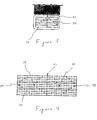
- FIG. 1 is a schematic diagram showing the typical direction of RF current flow throughout a vehicle body.
- FIG. 2 is a schematic diagram of one exemplary embodiment of a wire pattern layout of the present invention.
- FIG. 3 is a schematic diagram of one exemplary embodiment of a wire pattern layout of the present invention.
- FIG. 4 is a diagram of one exemplary embodiment of a wire pattern layout of the present invention.
- FIG. 5 is a plot of the impedance characteristics of the wire pattern layout shown in FIG. 4.
- FIG. 6 illustrates plots of the directional gain pattern of the wire pattern layout shown in FIG. 4.
- FIG. 7 is a diagram of one exemplary embodiment of a wire pattern layout of the present invention.
- FIG. 8 illustrates plots of the directional gain pattern of the wire pattern layout shown in FIG. 7.
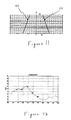
- FIG. 9 is a diagram of one exemplary embodiment of a wire pattern layout of the present invention.
- FIG. 10 is a plot of the test results of the wire pattern layout shown in FIG. 9.
- FIG. 11 is a diagram of one exemplary embodiment of a wire pattern layout of the present invention.
- FIG. 12 is a plot of the test results of the wire pattern layout shown in FIG. 11.
- FIG. 13 is a diagram of one exemplary embodiment of a wire pattern layout of the present invention.
- FIG. 14 is a plot of the test results of the wire pattern layout shown in FIG. 13.
- FIG. 15 is a diagram of one exemplary embodiment of a wire pattern layout of the present invention.
- FIG. 16 is a plot of the test results of the wire pattern layout shown in FIG. 15.
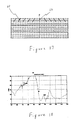
- FIG. 17 is a diagram of one exemplary embodiment of a wire pattern layout of the present invention.
- FIG. 18 is a plot of the test results of the wire pattern layout shown in FIG. 17.
- FIG. 19 is a diagram of one exemplary embodiment of a wire pattern layout of the present invention.
- FIG. 20 is a plot of the test results of the wire pattern layout shown in FIG. 19.
- FIG. 21 is a diagram of one exemplary embodiment of a wire pattern layout of the present invention.
- FIG. 22 is a plot of the test results of the wire pattern layout shown in FIG. 21.
- FIG. 23 is a diagram of one exemplary embodiment of a wire pattern layout of the present invention.
- FIG. 24 is a plot of the test results of the wire pattern layout shown in FIG. 23.
- FIG. 25 is a diagram of one exemplary embodiment of a wire pattern layout of the present invention.
- FIG. 26 is a plot of the test results of the wire pattern layout shown in FIG. 25.
- FIG. 27 is a diagram of one exemplary embodiment of a wire pattern layout of the present invention.
- FIG. 28 is a plot of the test results of the wire pattern layout shown in FIG. 27.
- FIG. 29 is a diagram of one exemplary embodiment of a wire pattern layout of the present invention.
- FIG. 30 is a diagram of an exemplary embodiment of an antenna layout of the present invention.
- FIG. 31 is a diagram of one embodiment of a window antenna of the present invention.
- FIG. 32 is a diagram of one embodiment of a wire pattern layout of the present invention.
- the present invention is directed to a layout for an antenna.
- the present invention will be described primarily herein with regard to a RF antenna embodiment for an automotive window. However, the present invention is not limited to that particular embodiment.
- the present invention may be useful for frequencies outside (i.e., above or below) of the RF range. Accordingly, the present invention is not limited to use with RF devices such AM and FM devices.
- the wire pattern layout of the present invention may be supported or otherwise suspended in any suitable dielectric material including, but not limited to, windows and other glass objects, plastics, air, or any other similar, suitable, or conventional dielectric material. Examples of glass include, but are not limited to, safety glass and fiberglass. Examples of plastics include, but are not limited to, polycarbonate and plexiglass.
- the present invention is not limited to a layout of an antenna for a vehicle or other automotive means.
- the present invention may be useful for any type of antenna application.
- wire shall be understood to include printed lines of conductive material, rigid filaments or rods of conductive material, flexible filaments or rods of conductive material, and other types of electrical conductors that are encompassed within the conventional meaning of the term wire.
- FIG. 1 is a schematic view which shows that a vehicle body may have an impact on the design of the wire pattern layout of an antenna.
- FIG. 1 shows a roof panel 10 that is situated adjacent to a window 12 .
- a metal panel 14 is secured to the window 12 .
- the metal panel 14 is in electrical communication with an antenna feed 16 .
- Theoretical equipotential lines 18 are shown for illustration purposes.
- RF current in the AM and FM frequency bands flows radially from the feed 16 as indicated by arrows 20 .
- the present invention takes this phenomenon into account in the design of the wire pattern layout of antenna. Consequently, exemplary embodiments of the present invention exhibit improved pattern control and impedance matching over the desired frequency band as compared to traditional wire pattern layouts.
- FIG. 2 shows one embodiment of a wire pattern layout of the present invention.
- a roof panel 22 is situated adjacent to a window 24 .
- a grid of approximately horizontal power wires 26 extend across the window.
- the power wires 26 may function as heating elements by conducting DC current, thereby defogging or defrosting the window 24 .
- An antenna feed 28 is in electrical communication with at least one antenna wire 30 .
- a plurality of antenna wires 30 traverse the power wires 26 .
- the antenna wires 30 of this embodiment include a plurality of oblique lines and one line that is approximately perpendicular to the power wires 26 . Accordingly, this embodiment of the wire pattern layout is an efficient and improved antenna design because it accommodates the natural direction of RF current flow.
- FIG. 3 shows another example of a wire pattern layout of the present invention.
- at least one antenna wire 32 is in electrical communication with a feed 34 and extends in a step pattern across the power lines 36 .
- This embodiment may offer some advantages over the embodiment of FIG. 2.
- each antenna wire 32 intersects adjacent power lines 36 at points of approximately equal voltage potential.
- this step pattern may substantially limit the possibility that an antenna wire 32 will also carry DC current that may be flowing through the power lines 36 .
- the oblique antenna wires 30 of FIG. 2 intersect adjacent power lines 26 at points of different voltage potential, which may result in the oblique antenna wires 30 also carrying DC current.
- the heating characteristics of the defogger or defroster may be negatively impacted if an antenna wire is carrying DC current. Consequently, the inventors have discovered that the embodiment of FIG. 3 may offer improved performance over the embodiment of FIG. 2, even though the embodiment of FIG. 2 may be a significant improvement over traditional designs.
- each layout of the present invention may be selected to achieve the desired antenna characteristics, which will vary according to the location and intended use of each antenna.
- FIG. 4 illustrates a wire pattern layout in which each antenna line 38 changes direction in a step-wise fashion while traversing the grid of substantially horizontal power lines 40 .
- each antenna line 38 is generally V-shaped. It should be recognized that the direction of an antenna wire may change multiple times and have, for example, a W-shape.
- FIG. 5 is a plot of the impedance characteristics of the embodiment shown in FIG. 4, and FIG. 6 shows plots of the direction gain pattern at different frequencies of the embodiment shown in FIG. 4. In each instance, the embodiment of FIG. 4 provided significantly improved results over traditional wire pattern layouts.
- FIG. 7 shows an embodiment of the present invention that is comprised of a plurality of intersecting antenna wires.
- at least one approximately vertically oriented antenna wire 44 traverses a plurality of approximately horizontally oriented antenna wires 46 .
- Each of the antenna wires 46 , 48 is in electrical communication with an antenna feed 48 .
- This layout utilizes a sufficient number of wire interconnects to permit a natural flow of RF current over the entire pattern. Consequently, this embodiment also offered directional gains as shown in FIG. 8 that compare very well to traditional on-glass antennas.
- an antenna wire pattern such as shown in FIG. 7 may be used alone or in conjunction with another antenna wire pattern.
- one antenna wire pattern may be in direct electrical communication with, or electromagnetically coupled to, another antenna wire pattern.
- a number of other wire pattern layouts were tested using a network analyzer to measure the S 11 parameter of each configuration.
- the antenna feed is indicated as F.
- FIG. 9 The layout of FIG. 9 has one vertical antenna wire 50 that traverses the heater grid.
- the test results of this embodiment are shown in FIG. 10.
- the wire pattern of FIG. 11 has two oblique antenna wires 52 that extend across the heater grid.
- the distance a is about 11.5 cm, and the distance b is about 26 cm.
- the test results of this wire pattern are shown in FIG. 12.
- the wire pattern of FIG. 13 also has two oblique antenna lines 54 that extend across the heater grid. However, in this embodiment, the distance a is about 21.5 cm, and the distance b is about 36 cm. The test results of this wire pattern are shown in FIG. 14.
- the wire pattern layout has two oblique antenna lines 56 as well as a vertical antenna line 58 .
- the distance a is about 21.5 cm
- the distance b is about 36 cm.
- the test results of this wire pattern are shown in FIG. 16.
- FIG. 17 is comprised of 10 oblique antenna lines 60 and 1 substantially vertical antenna line 62 .
- the antenna wires 60 , 62 only traverse the first three power lines of the heater grid.
- FIG. 18 shows the test results for this example.
- FIG. 19 illustrates an embodiment in which an antenna array 64 is over and isolated from the heater grid 66 .
- the antenna array 64 has a side antenna feed F.
- the antenna pattern 64 does not traverse the heater grid 66 .
- the test results are shown in FIG. 20.
- FIG. 21 The layout of FIG. 21 is similar to the layout of FIG. 19, except that there is a central antenna feed F.
- FIG. 22 shows the test result for this embodiment.
- FIG. 23 shows three substantially vertical antenna wires 68 traversing the heater grid. The test results regarding the layout of FIG. 23 are shown in FIG. 24.
- the layout is comprised of a vertical antenna line 70 and two “rhomboidal” antenna lines 72 .
- each of the “rhomboidal” antenna lines 72 have one change in direction, thereby forming a V-shape.
- the test results are shown in FIG. 26.
- FIG. 27 shows a wire pattern layout in which four “rhomboidal” antenna wires 74 traverse the heater grid.
- the results of the testing of this embodiment are shown in FIG. 28.
- FIG. 29 illustrates a wire pattern layout that includes a wire array 76 that is situated above and substantially adjacent to a wire array 78 .
- the wire array 76 includes an antenna line 80 .
- the antenna line 80 is situated sufficiently adjacent to the wire array 78 to form a capacitive or electromagnetic connection.
- the wire array 76 is comprised of a plurality of intersecting antenna wires, such as described with regard to FIG. 7.
- the wire array 78 is similar to the embodiment of FIG. 4 in that a plurality of antenna wires traverse the heater grid in a step-wise pattern.
- the upper wire array may be in direct electrical communication with the lower wire array.
- FIG. 30 shows a film embodiment of a layout of the present invention.
- a metallic film 82 is in electrical communication with an antenna feed 84 .
- the metallic film 82 may have any suitable shape for facilitating RF transmission in the desired frequency band.
- the metallic film 82 may be transparent for use in a window embodiment, for example. However, it should also be recognized that the metallic film 82 may be translucent or opaque in other embodiments.
- the metallic film 82 may be supported in any suitable dielectric material including, but not limited to, glass, polycarbonate, plastic, or any other similar, suitable, or conventional dielectric material.
- the metallic film 82 may be secured to an outer surface or in between layers of the dielectric material using any suitable manufacturing technique such as vacuum deposition or extrusion. For example, the metallic layer 82 may be sputtered on an outer surface or in between layers of the dielectric material.
- the metallic film 82 may be used alone or in conjunction with at least one other antenna wire pattern.
- the metallic layer 82 may be in direct electrical communication with, or electromagnetically coupled to, another antenna wire pattern.
- the metallic film 82 may be substituted for the upper antenna wire patterns of the embodiments shown in FIGS. 17, 19, 21 , and 29 .
- the metallic layer 82 may be supported by a plastic frame that extends at least partially around a glass window.
- FIG. 31 shows one example of this embodiment.
- the metallic layer 86 is supported by a plastic frame 88 .
- the plastic frame 88 extends around a glass panel 90 which has a heater grid pattern 92 .
- the metallic film may be in direct communication with, or electromagnetically coupled to, another antenna wire pattern that intersects the heater grid pattern 92 .
- a metallic film may be substituted for the heater grid pattern, wherein the metallic film may be adapted to block infrared radiation and/or to conduct electricity for heating purposes.
- any other embodiment of the present invention may be supported in dielectric material comprised of a plastic frame that extends at least partially around a glass panel.
- FIG. 32 shows another example in which one wire pattern layout is electromagnetically coupled to another wire pattern layout.
- wire pattern array 94 is electromagnetically coupled to wire pattern array 96 via an antenna line 98 of wire pattern array 94 .
- the wire pattern array 94 may be in direct electrical communication with the wire pattern array 96 .
- the wire pattern array 94 also has an antenna line 100 that may extend at least partially around the periphery of the wire pattern array 96 . The inventors have surprisingly discovered that the antenna line 100 may be useful to improve reception in the AM band.
- the main grid of wire pattern array 94 is comprised of a plurality of intersecting wires similar to the embodiment of FIG. 7.
- the wire pattern array 94 may also be similar to the upper patterns of FIG. 17, 19, or 21 or any other embodiment having a plurality of intersecting antenna wires.
- a metallic film similar to the example of FIG. 30 may be substituted for the main grid of wire pattern array 94 .
- the wire pattern array 96 may be comprised of at least one antenna wire that intersects a heater grid.
- the wire pattern array 96 may be similar to the examples of FIGS. 2, 3, 4 , 9 , 11 , 13 , 15 , 23 , 25 , 27 , or any other suitable embodiment in which at least one antenna wire intersects a heater grid.
- the present invention includes other embodiments that may be obtained by combining or substituting the exemplary embodiments.
- the exemplary embodiments herein disclosed are not intended to be exhaustive or to unnecessarily limit the scope of the invention.
- the exemplary embodiments were chosen and described in order to explain the principles of the present invention so that others skilled in the art may practice the invention. Having shown and described exemplary embodiments of the present invention, those skilled in the art will realize that many variations and modifications may be made to affect the described invention. Many of those variations and modifications will provide the same result and fall within the spirit of the claimed invention. It is the intention, therefore, to limit the invention only as indicated by the scope of the claims.
Landscapes
- Details Of Aerials (AREA)
- Fittings On The Vehicle Exterior For Carrying Loads, And Devices For Holding Or Mounting Articles (AREA)
Abstract
Description
- The present invention relates generally to a layout for an antenna. More particularly, the present invention relates primarily to a layout for a radio frequency (RF) antenna. An example of a RF antenna is a window antenna for a vehicle or other automotive means.
- Modern automotive means may need an antenna to support RF communication. A number of devices may function using RF communication. For instance, AM radios, FM radios, AM/FM radios, CB radios, cellular phones, and global positioning systems are dependent on RF communication.
- A modern automobile may have a glass window that serves as a dielectric support for a wire pattern layout of a RF antenna. Typically, a rear window is used for such purposes. A pattern of wires printed or imbedded in the glass (i.e., printed lines) may permit RF current flow to and from the desired RF device.
- The rear window of a typical automobile also has a pattern of printed lines that enables DC current flow. DC current causes these printed lines to act as heating elements. As a result, these lines may be used to defrost or defog the rear window, thereby enabling a driver to see out the rear window. To adequately serve this purpose, the heating elements typically cover a substantial area of the rear window. As a result, there is usually insufficient area for an isolated wire pattern layout for a traditional RF antenna. Consequently, the heating elements interfere with operation of the traditional RF antenna, causing the traditional RF antenna to exhibit relatively poor pattern control and impedance matching over the desired frequency band.
- The present invention provides an improved layout for an antenna. The antenna design of present invention takes into account the characteristics of RF current flow and the impact of a heater grid pattern. As a result, exemplary embodiments of the present invention provide improved directional gain patterns and impedance characteristics as compared to traditional window antenna designs.
- One embodiment of a wire pattern layout comprises a plurality of power wires and an antenna wire. The power wires are adapted to be in electrical communication with a power source, e.g., a DC power source. An example of the power wires includes, but is not limited to, the printed lines of a heater grid pattern. The power wires may be arranged in any desired pattern. In a common heater grid pattern, the power wires are arranged in approximately parallel rows. The antenna wire traverses some or all of the power wires. In one embodiment, the antenna wire has a configuration that extends at an oblique angle across the power wires. In other words, an imaginary axis or generally central line of the configuration extends at an oblique angle across the power wires. There may be at least one change of direction of the configuration as the antenna wire extends across the power wires. The antenna wire is adapted to be in electrical communication with a feed to a radio frequency device.
- The shape of the antenna wire may be selected to achieve optimal pattern control and impedance characteristics. In one exemplary embodiment, the antenna wire has a substantially straight line configuration. In another exemplary embodiment, the configuration of the antenna wire is a step pattern. The angle of each step may be selected to achieve the optimal antenna characteristics. The inventors have discovered that steps of about 90 degrees may be preferred in some embodiments to prevent or limit interference with the heater grid power flow. In other words, the antenna wire may intersect each power wire at an angle of approximately 90 degrees to limit interference with the heater grid power flow. For optimal results in some embodiments, there may be at least one change in direction of the antenna wire. For instance, a straight line may change directions, or a step pattern may change directions. In one exemplary embodiment, the antenna wire may have a “V” or “W” shape. Of course, some embodiments of the present invention may include at least one additional antenna wire that is also adapted to be in electrical communication with the feed to the radio frequency device. Each additional antenna wire may include any of the optional or preferred features of the above-described antenna wire.
- The wire pattern layout may be supported by any suitable means. For example, the power wires and the antenna wire(s) may be printed lines that are supported by at least one dielectric panel. One example of a dielectric panel is an automotive window.
- The antenna wire(s) may be adapted to be in electrical communication with any suitable device. For instance, the antenna wire(s) may be connected to a suitable RF device. Examples of RF devices include, but are not limited to, AM radios, FM radios, AM/FM radios, CB radios, global positioning systems, cellular phones, and various combinations of such devices.
- The present invention includes another embodiment of a wire pattern layout for an antenna. This embodiment may include any of the optional or preferred features of the other embodiments of the present invention. In this embodiment, the wire pattern layout comprises at least one dielectric panel that supports a plurality of power wires, an antenna feed, and a plurality of antenna wires. The power wires are in electrical communication with a power source, and the feed is in electrical communication with a radio frequency device. The antenna wires are in electrical communication with the feed. At least one of the antenna wires has a configuration that extends at an oblique angle across the power wires.
- Yet another embodiment of a wire pattern layout for an antenna is included in the present invention. This embodiment may include any of the optional or preferred features of the other embodiments of the present invention. This example of the wire pattern layout comprises an antenna feed and two wire arrays. The feed is adapted to be in electrical communication with a radio frequency device. The first wire array is in electrical communication with the feed. The first wire array comprises a plurality of intersecting antenna wires. In one exemplary embodiment, the first wire array may also include an additional antenna wire that extends at least partially around the second wire array. The second wire array comprises a plurality of power wires and at least one antenna wire. The first wire array may be electromagnetically coupled to the antenna wire(s) of the second wire array. In one example, a coupling wire may be connected to the first wire array, wherein the coupling wire facilitates electromagnetic coupling of the first wire array to the antenna wire(s) of the second wire array. The power wires are adapted to be in electrical communication with a power source, and the antenna wire(s) of the second wire array traverse the power wires. In one exemplary embodiment, an antenna wire of the second wire array may have a configuration that extends at an oblique angle across the power wires. In other embodiments, an antenna wire of the second wire array may be a straight line that is perpendicular to the power wires.
- The antenna wires of the first array may intersect in any suitable pattern. In one embodiment, the intersecting antenna wires of the first wire array may include a plurality of approximately horizontally oriented antenna wires and at least one approximately vertically oriented antenna wire. The approximately vertically oriented antenna wire may traverse some or all of the approximately horizontally oriented antenna wires. As in previously described embodiments, the antenna wires of the first and second wire arrays may include any suitable shapes. In an exemplary embodiment, the first and second wire arrays are supported by a window of an automobile, and the first wire array is situated above and substantially adjacent to the second wire array.
- In another embodiment of the present invention, a wire pattern layout for an antenna comprises two antenna wires that are coupled together. A feed is adapted to be in electrical communication with a radio frequency device. A first antenna wire is in electrical communication with the feed. The second antenna wire is included in a wire array. The wire array also includes a plurality of power wires that are adapted to be in electrical communication with a power source. The second antenna wire intersects the power wires, and it is electromagnetically coupled to the first antenna wire. This embodiment of the present invention may also include any of the optional or preferred features of the other embodiments of the present invention.
- The present invention includes another embodiment of an antenna layout. This example may include any of the optional or preferred features of the other embodiments of the present invention. In this example, a feed is adapted to be in electrical communication with a radio frequency device. A metallic film is in electrical communication with the feed. A wire array may also be included. The wire array comprises a plurality of power wires, and it is adapted to be in electrical communication with a power source. The metallic film and the wire array are supported by at least one dielectric panel.
- Another embodiment of the present invention includes a first dielectric panel that is connected to a second dielectric panel. An antenna is supported by the first dielectric panel, whereas the second dielectric panel supports a heater layout. The heater layout may comprise a plurality of power wires adapted to be in electrical communication with a power source. The dielectric panels may be comprised of any suitable dielectric materials. In one example, the first dielectric panel is comprised of plastic, and the second dielectric panel is comprised of glass. Some other examples of dielectric materials include, but are not limited to, safety glass, polycarbonate, plexiglass, and fiberglass. In addition, this embodiment may include any of the optional or preferred features of the other embodiments of the present invention.
- In addition to the novel features and advantages mentioned above, other features and advantages of the present invention Will be readily apparent from the following descriptions of the drawings and exemplary embodiments.
- FIG. 1 is a schematic diagram showing the typical direction of RF current flow throughout a vehicle body.
- FIG. 2 is a schematic diagram of one exemplary embodiment of a wire pattern layout of the present invention.
- FIG. 3 is a schematic diagram of one exemplary embodiment of a wire pattern layout of the present invention.
- FIG. 4 is a diagram of one exemplary embodiment of a wire pattern layout of the present invention.
- FIG. 5 is a plot of the impedance characteristics of the wire pattern layout shown in FIG. 4.
- FIG. 6 illustrates plots of the directional gain pattern of the wire pattern layout shown in FIG. 4.
- FIG. 7 is a diagram of one exemplary embodiment of a wire pattern layout of the present invention.
- FIG. 8 illustrates plots of the directional gain pattern of the wire pattern layout shown in FIG. 7.
- FIG. 9 is a diagram of one exemplary embodiment of a wire pattern layout of the present invention.
- FIG. 10 is a plot of the test results of the wire pattern layout shown in FIG. 9.
- FIG. 11 is a diagram of one exemplary embodiment of a wire pattern layout of the present invention.
- FIG. 12 is a plot of the test results of the wire pattern layout shown in FIG. 11.
- FIG. 13 is a diagram of one exemplary embodiment of a wire pattern layout of the present invention.
- FIG. 14 is a plot of the test results of the wire pattern layout shown in FIG. 13.
- FIG. 15 is a diagram of one exemplary embodiment of a wire pattern layout of the present invention.
- FIG. 16 is a plot of the test results of the wire pattern layout shown in FIG. 15.
- FIG. 17 is a diagram of one exemplary embodiment of a wire pattern layout of the present invention.
- FIG. 18 is a plot of the test results of the wire pattern layout shown in FIG. 17.
- FIG. 19 is a diagram of one exemplary embodiment of a wire pattern layout of the present invention.
- FIG. 20 is a plot of the test results of the wire pattern layout shown in FIG. 19.
- FIG. 21 is a diagram of one exemplary embodiment of a wire pattern layout of the present invention.
- FIG. 22 is a plot of the test results of the wire pattern layout shown in FIG. 21.
- FIG. 23 is a diagram of one exemplary embodiment of a wire pattern layout of the present invention.
- FIG. 24 is a plot of the test results of the wire pattern layout shown in FIG. 23.
- FIG. 25 is a diagram of one exemplary embodiment of a wire pattern layout of the present invention.
- FIG. 26 is a plot of the test results of the wire pattern layout shown in FIG. 25.
- FIG. 27 is a diagram of one exemplary embodiment of a wire pattern layout of the present invention.
- FIG. 28 is a plot of the test results of the wire pattern layout shown in FIG. 27.
- FIG. 29 is a diagram of one exemplary embodiment of a wire pattern layout of the present invention.
- FIG. 30 is a diagram of an exemplary embodiment of an antenna layout of the present invention.
- FIG. 31 is a diagram of one embodiment of a window antenna of the present invention.
- FIG. 32 is a diagram of one embodiment of a wire pattern layout of the present invention.
- The present invention is directed to a layout for an antenna. The present invention will be described primarily herein with regard to a RF antenna embodiment for an automotive window. However, the present invention is not limited to that particular embodiment. The present invention may be useful for frequencies outside (i.e., above or below) of the RF range. Accordingly, the present invention is not limited to use with RF devices such AM and FM devices. Also, the wire pattern layout of the present invention may be supported or otherwise suspended in any suitable dielectric material including, but not limited to, windows and other glass objects, plastics, air, or any other similar, suitable, or conventional dielectric material. Examples of glass include, but are not limited to, safety glass and fiberglass. Examples of plastics include, but are not limited to, polycarbonate and plexiglass. Furthermore, the present invention is not limited to a layout of an antenna for a vehicle or other automotive means. The present invention may be useful for any type of antenna application. As used herein, the term wire shall be understood to include printed lines of conductive material, rigid filaments or rods of conductive material, flexible filaments or rods of conductive material, and other types of electrical conductors that are encompassed within the conventional meaning of the term wire.
- FIG. 1 is a schematic view which shows that a vehicle body may have an impact on the design of the wire pattern layout of an antenna. FIG. 1 shows a
roof panel 10 that is situated adjacent to awindow 12. Ametal panel 14 is secured to thewindow 12. Themetal panel 14 is in electrical communication with anantenna feed 16. Theoreticalequipotential lines 18 are shown for illustration purposes. In such an embodiment, RF current in the AM and FM frequency bands flows radially from thefeed 16 as indicated byarrows 20. As a result, the entire body of the vehicle essentially becomes a part of the antenna as the RF current flows throughout the metal panels of the vehicle body. Accordingly, the present invention takes this phenomenon into account in the design of the wire pattern layout of antenna. Consequently, exemplary embodiments of the present invention exhibit improved pattern control and impedance matching over the desired frequency band as compared to traditional wire pattern layouts. - FIG. 2 shows one embodiment of a wire pattern layout of the present invention. In FIG. 2, a
roof panel 22 is situated adjacent to awindow 24. A grid of approximately horizontal power wires 26 extend across the window. For example, the power wires 26 may function as heating elements by conducting DC current, thereby defogging or defrosting thewindow 24. Anantenna feed 28 is in electrical communication with at least oneantenna wire 30. In this example, a plurality ofantenna wires 30 traverse the power wires 26. Theantenna wires 30 of this embodiment include a plurality of oblique lines and one line that is approximately perpendicular to the power wires 26. Accordingly, this embodiment of the wire pattern layout is an efficient and improved antenna design because it accommodates the natural direction of RF current flow. - FIG. 3 shows another example of a wire pattern layout of the present invention. In this embodiment, at least one
antenna wire 32 is in electrical communication with afeed 34 and extends in a step pattern across thepower lines 36. This embodiment may offer some advantages over the embodiment of FIG. 2. By implementing a step pattern, eachantenna wire 32 intersectsadjacent power lines 36 at points of approximately equal voltage potential. As a result, this step pattern may substantially limit the possibility that anantenna wire 32 will also carry DC current that may be flowing through thepower lines 36. On the other hand, theoblique antenna wires 30 of FIG. 2 intersect adjacent power lines 26 at points of different voltage potential, which may result in theoblique antenna wires 30 also carrying DC current. The heating characteristics of the defogger or defroster may be negatively impacted if an antenna wire is carrying DC current. Consequently, the inventors have discovered that the embodiment of FIG. 3 may offer improved performance over the embodiment of FIG. 2, even though the embodiment of FIG. 2 may be a significant improvement over traditional designs. - Based on the aforementioned concepts, a number of designs have been built and tested. However, the present invention is not limited to the exemplary dimensions and configurations provided throughout the examples. The dimensions and configuration of each layout of the present invention may be selected to achieve the desired antenna characteristics, which will vary according to the location and intended use of each antenna.
- FIG. 4 illustrates a wire pattern layout in which each
antenna line 38 changes direction in a step-wise fashion while traversing the grid of substantiallyhorizontal power lines 40. In this particular embodiment, eachantenna line 38 is generally V-shaped. It should be recognized that the direction of an antenna wire may change multiple times and have, for example, a W-shape. FIG. 5 is a plot of the impedance characteristics of the embodiment shown in FIG. 4, and FIG. 6 shows plots of the direction gain pattern at different frequencies of the embodiment shown in FIG. 4. In each instance, the embodiment of FIG. 4 provided significantly improved results over traditional wire pattern layouts. - FIG. 7 shows an embodiment of the present invention that is comprised of a plurality of intersecting antenna wires. In this embodiment, at least one approximately vertically oriented
antenna wire 44 traverses a plurality of approximately horizontally orientedantenna wires 46. Each of theantenna wires antenna feed 48. This layout utilizes a sufficient number of wire interconnects to permit a natural flow of RF current over the entire pattern. Consequently, this embodiment also offered directional gains as shown in FIG. 8 that compare very well to traditional on-glass antennas. It should be recognized that an antenna wire pattern such as shown in FIG. 7 may be used alone or in conjunction with another antenna wire pattern. For example, one antenna wire pattern may be in direct electrical communication with, or electromagnetically coupled to, another antenna wire pattern. - A number of other wire pattern layouts were tested using a network analyzer to measure the S 11 parameter of each configuration. The dimensions of the heater grid used in each of the tests were approximately: top length=100 cm; bottom length=118 cm; and height=30 cm. In each of the remaining diagrams of the exemplary wire pattern layouts, the antenna feed is indicated as F.
- The layout of FIG. 9 has one
vertical antenna wire 50 that traverses the heater grid. The test results of this embodiment are shown in FIG. 10. - The wire pattern of FIG. 11 has two
oblique antenna wires 52 that extend across the heater grid. The distance a is about 11.5 cm, and the distance b is about 26 cm. The test results of this wire pattern are shown in FIG. 12. - The wire pattern of FIG. 13 also has two
oblique antenna lines 54 that extend across the heater grid. However, in this embodiment, the distance a is about 21.5 cm, and the distance b is about 36 cm. The test results of this wire pattern are shown in FIG. 14. - In FIG. 15, the wire pattern layout has two
oblique antenna lines 56 as well as avertical antenna line 58. In this embodiment, the distance a is about 21.5 cm, and the distance b is about 36 cm. The test results of this wire pattern are shown in FIG. 16. - The embodiment of FIG. 17 is comprised of 10
oblique antenna lines vertical antenna line 62. Theantenna wires - FIG. 19 illustrates an embodiment in which an
antenna array 64 is over and isolated from theheater grid 66. Theantenna array 64 has a side antenna feed F. In this embodiment of the present invention, theantenna pattern 64 does not traverse theheater grid 66. The test results are shown in FIG. 20. - The layout of FIG. 21 is similar to the layout of FIG. 19, except that there is a central antenna feed F. FIG. 22 shows the test result for this embodiment.
- FIG. 23 shows three substantially
vertical antenna wires 68 traversing the heater grid. The test results regarding the layout of FIG. 23 are shown in FIG. 24. - In FIG. 25, the layout is comprised of a
vertical antenna line 70 and two “rhomboidal” antenna lines 72. In this particular example, each of the “rhomboidal”antenna lines 72 have one change in direction, thereby forming a V-shape. The test results are shown in FIG. 26. - FIG. 27 shows a wire pattern layout in which four “rhomboidal”
antenna wires 74 traverse the heater grid. In this embodiment, the distances were approximately: a=20 cm; b=16; c=15 cm; d=15 cm; e=4 cm; and f=11 cm. The results of the testing of this embodiment are shown in FIG. 28. - FIG. 29 illustrates a wire pattern layout that includes a
wire array 76 that is situated above and substantially adjacent to awire array 78. Thewire array 76 includes anantenna line 80. Theantenna line 80 is situated sufficiently adjacent to thewire array 78 to form a capacitive or electromagnetic connection. Thewire array 76 is comprised of a plurality of intersecting antenna wires, such as described with regard to FIG. 7. On the other hand, thewire array 78 is similar to the embodiment of FIG. 4 in that a plurality of antenna wires traverse the heater grid in a step-wise pattern. In one variation of the embodiment shown in FIG. 29, the upper wire array may be in direct electrical communication with the lower wire array. - FIG. 30 shows a film embodiment of a layout of the present invention. In this embodiment, a
metallic film 82 is in electrical communication with anantenna feed 84. Themetallic film 82 may have any suitable shape for facilitating RF transmission in the desired frequency band. Themetallic film 82 may be transparent for use in a window embodiment, for example. However, it should also be recognized that themetallic film 82 may be translucent or opaque in other embodiments. Themetallic film 82 may be supported in any suitable dielectric material including, but not limited to, glass, polycarbonate, plastic, or any other similar, suitable, or conventional dielectric material. Themetallic film 82 may be secured to an outer surface or in between layers of the dielectric material using any suitable manufacturing technique such as vacuum deposition or extrusion. For example, themetallic layer 82 may be sputtered on an outer surface or in between layers of the dielectric material. - Similar to the wire pattern layout of FIG. 7, the
metallic film 82 may be used alone or in conjunction with at least one other antenna wire pattern. In other words, themetallic layer 82 may be in direct electrical communication with, or electromagnetically coupled to, another antenna wire pattern. For example, themetallic film 82 may be substituted for the upper antenna wire patterns of the embodiments shown in FIGS. 17, 19, 21, and 29. - In one embodiment, the
metallic layer 82 may be supported by a plastic frame that extends at least partially around a glass window. FIG. 31 shows one example of this embodiment. In FIG. 31, themetallic layer 86 is supported by aplastic frame 88. Theplastic frame 88 extends around aglass panel 90 which has aheater grid pattern 92. As shown in this embodiment, the metallic film may be in direct communication with, or electromagnetically coupled to, another antenna wire pattern that intersects theheater grid pattern 92. In one variation of this embodiment, a metallic film may be substituted for the heater grid pattern, wherein the metallic film may be adapted to block infrared radiation and/or to conduct electricity for heating purposes. Furthermore, it should be recognized that any other embodiment of the present invention may be supported in dielectric material comprised of a plastic frame that extends at least partially around a glass panel. - FIG. 32 shows another example in which one wire pattern layout is electromagnetically coupled to another wire pattern layout. In this example,
wire pattern array 94 is electromagnetically coupled towire pattern array 96 via anantenna line 98 ofwire pattern array 94. In a variation of this example, thewire pattern array 94 may be in direct electrical communication with thewire pattern array 96. Thewire pattern array 94 also has anantenna line 100 that may extend at least partially around the periphery of thewire pattern array 96. The inventors have surprisingly discovered that theantenna line 100 may be useful to improve reception in the AM band. - In this example, the main grid of
wire pattern array 94 is comprised of a plurality of intersecting wires similar to the embodiment of FIG. 7. Thewire pattern array 94 may also be similar to the upper patterns of FIG. 17, 19, or 21 or any other embodiment having a plurality of intersecting antenna wires. It should also be recognized that a metallic film similar to the example of FIG. 30 may be substituted for the main grid ofwire pattern array 94. On the other hand, thewire pattern array 96 may be comprised of at least one antenna wire that intersects a heater grid. For example, thewire pattern array 96 may be similar to the examples of FIGS. 2, 3, 4, 9, 11, 13, 15, 23, 25, 27, or any other suitable embodiment in which at least one antenna wire intersects a heater grid. - The present invention includes other embodiments that may be obtained by combining or substituting the exemplary embodiments. The exemplary embodiments herein disclosed are not intended to be exhaustive or to unnecessarily limit the scope of the invention. The exemplary embodiments were chosen and described in order to explain the principles of the present invention so that others skilled in the art may practice the invention. Having shown and described exemplary embodiments of the present invention, those skilled in the art will realize that many variations and modifications may be made to affect the described invention. Many of those variations and modifications will provide the same result and fall within the spirit of the claimed invention. It is the intention, therefore, to limit the invention only as indicated by the scope of the claims.
Claims (59)
Priority Applications (9)
| Application Number | Priority Date | Filing Date | Title |
|---|---|---|---|
| US10/127,915 US6693597B2 (en) | 2002-04-23 | 2002-04-23 | Layout for automotive window antenna |
| DE60335539T DE60335539D1 (en) | 2002-04-23 | 2003-04-22 | LAYOUT FOR A MOTOR VEHICLE ANTENNA |
| RU2004134340/09A RU2312433C2 (en) | 2002-04-23 | 2003-04-22 | Arrangement of antenna for car window |
| PCT/US2003/012408 WO2003092117A2 (en) | 2002-04-23 | 2003-04-22 | Layout for automotive window antenna |
| CNA038093146A CN1650470A (en) | 2002-04-23 | 2003-04-22 | Layout for automotive window antenna |
| EP03731037A EP1502321B1 (en) | 2002-04-23 | 2003-04-22 | Layout for automotive window antenna |
| JP2004500365A JP4299235B2 (en) | 2002-04-23 | 2003-04-22 | Automotive window glass antenna layout |
| AU2003241306A AU2003241306A1 (en) | 2002-04-23 | 2003-04-22 | Layout for automotive window antenna |
| BR0309497-9A BR0309497A (en) | 2002-04-23 | 2003-04-22 | Array for an antenna |
Applications Claiming Priority (1)
| Application Number | Priority Date | Filing Date | Title |
|---|---|---|---|
| US10/127,915 US6693597B2 (en) | 2002-04-23 | 2002-04-23 | Layout for automotive window antenna |
Publications (2)
| Publication Number | Publication Date |
|---|---|
| US20030197650A1 true US20030197650A1 (en) | 2003-10-23 |
| US6693597B2 US6693597B2 (en) | 2004-02-17 |
Family
ID=29215363
Family Applications (1)
| Application Number | Title | Priority Date | Filing Date |
|---|---|---|---|
| US10/127,915 Expired - Lifetime US6693597B2 (en) | 2002-04-23 | 2002-04-23 | Layout for automotive window antenna |
Country Status (9)
| Country | Link |
|---|---|
| US (1) | US6693597B2 (en) |
| EP (1) | EP1502321B1 (en) |
| JP (1) | JP4299235B2 (en) |
| CN (1) | CN1650470A (en) |
| AU (1) | AU2003241306A1 (en) |
| BR (1) | BR0309497A (en) |
| DE (1) | DE60335539D1 (en) |
| RU (1) | RU2312433C2 (en) |
| WO (1) | WO2003092117A2 (en) |
Cited By (4)
| Publication number | Priority date | Publication date | Assignee | Title |
|---|---|---|---|---|
| EP1686646A1 (en) * | 2005-01-28 | 2006-08-02 | CALEARO ANTENNE S.P.A. a socio unico | Vehicle antenna array |
| US20070223107A1 (en) * | 2004-05-15 | 2007-09-27 | Azusa Noguchi | Zoom optical system and imaging apparatus using the same |
| WO2016072620A1 (en) * | 2014-11-07 | 2016-05-12 | Samsung Electronics Co., Ltd. | Antenna device |
| US20160172742A1 (en) * | 2014-12-10 | 2016-06-16 | Avery Dennison Retail Information Services, Llc | Edge on foam tags |
Families Citing this family (14)
| Publication number | Priority date | Publication date | Assignee | Title |
|---|---|---|---|---|
| US7295154B2 (en) * | 2002-01-17 | 2007-11-13 | The Ohio State University | Vehicle obstacle warning radar |
| US6860081B2 (en) * | 2002-12-04 | 2005-03-01 | The Ohio State University | Sidelobe controlled radio transmission region in metallic panel |
| US7196657B2 (en) * | 2003-01-31 | 2007-03-27 | The Ohio State University | Radar system using RF noise |
| BRPI0418862A (en) * | 2004-05-27 | 2007-11-20 | Thomson Licensing | apparatus for checking a low noise block output voltage |
| JP2006140789A (en) * | 2004-11-12 | 2006-06-01 | Hitachi Cable Ltd | Invisible antenna |
| KR20070113128A (en) * | 2006-05-23 | 2007-11-28 | 아사히 가라스 가부시키가이샤 | Automotive High Frequency Glass Antenna |
| JP4919770B2 (en) * | 2006-11-13 | 2012-04-18 | セントラル硝子株式会社 | Automotive window glass |
| US7742006B2 (en) * | 2006-12-28 | 2010-06-22 | Agc Automotive Americas R&D, Inc. | Multi-band loop antenna |
| US7742005B2 (en) * | 2006-12-28 | 2010-06-22 | Agc Automotive Americas R&D, Inc. | Multi-band strip antenna |
| US7586452B2 (en) * | 2007-01-15 | 2009-09-08 | Agc Automotive Americas R&D, Inc. | Multi-band antenna |
| US8776002B2 (en) | 2011-09-06 | 2014-07-08 | Variable Z0, Ltd. | Variable Z0 antenna device design system and method |
| WO2014008508A1 (en) | 2012-07-06 | 2014-01-09 | The Ohio State University | Compact dual band gnss antenna design |
| WO2015137108A1 (en) * | 2014-03-12 | 2015-09-17 | 旭硝子株式会社 | Automotive glass antenna |
| CN112088464B (en) | 2019-03-18 | 2025-03-21 | Ask工业股份公司 | Method for manufacturing a vehicle rear window with an antenna having an integrated heater |
Family Cites Families (24)
| Publication number | Priority date | Publication date | Assignee | Title |
|---|---|---|---|---|
| US4475108A (en) | 1982-08-04 | 1984-10-02 | Allied Corporation | Electronically tunable microstrip antenna |
| US4764773A (en) | 1985-07-30 | 1988-08-16 | Larsen Electronics, Inc. | Mobile antenna and through-the-glass impedance matched feed system |
| US5014346A (en) | 1988-01-04 | 1991-05-07 | Motorola, Inc. | Rotatable contactless antenna coupler and antenna |
| DE3906592C2 (en) * | 1989-03-02 | 1994-05-26 | Kolbe & Co Hans | Motor vehicle antenna, preferably for FM radio reception |
| DE3907493A1 (en) | 1989-03-08 | 1990-09-20 | Lindenmeier Heinz | DISC ANTENNA WITH ANTENNA AMPLIFIER |
| US5266960A (en) * | 1989-05-01 | 1993-11-30 | Fuba Hans Kolbe Co. | Pane antenna having at least one wire-like antenna conductor combined with a set of heating wires |
| JPH082926Y2 (en) | 1991-03-29 | 1996-01-29 | 日本板硝子株式会社 | Antenna connector |
| US5355144A (en) * | 1992-03-16 | 1994-10-11 | The Ohio State University | Transparent window antenna |
| RU2058634C1 (en) * | 1992-03-24 | 1996-04-20 | Военная академия связи | Automobile antenna |
| KR0145052B1 (en) * | 1993-12-29 | 1998-08-01 | 와다 요시히로 | Insulator for vehicle body, vehicle antenna and its setting method |
| US6268832B1 (en) * | 1994-09-28 | 2001-07-31 | Bsh Industries Limited | Radio antenna for vehicle window |
| US5952977A (en) * | 1994-11-04 | 1999-09-14 | Mazda Motor Corporation | Glass antenna |
| US5577269A (en) | 1995-04-21 | 1996-11-19 | E. F. Johnson Company | Antenna connector for a portable radio |
| JPH0918222A (en) | 1995-06-28 | 1997-01-17 | Nippon Sheet Glass Co Ltd | Window glass antenna device |
| DE19527304C1 (en) * | 1995-07-26 | 1996-10-31 | Flachglas Ag | Car window pane for reception of UHF radio waves |
| US5739790A (en) | 1995-09-18 | 1998-04-14 | Nippondenso, Co., Ltd. | RF docking adapter for portable transceivers, communication system and method for use with the same |
| GB2309829B (en) * | 1996-01-23 | 2000-02-16 | Wipac Group Limited | Vehicle on-screen antenna |
| US5812098A (en) | 1996-11-26 | 1998-09-22 | Sharp Microelectronics Technology, Inc. | Retractable antenna connector assembly system and method |
| US5999134A (en) | 1996-12-19 | 1999-12-07 | Ppg Industries Ohio, Inc. | Glass antenna system with an impedance matching network |
| EP0854534A1 (en) | 1997-01-16 | 1998-07-22 | Nippon Sheet Glass Co. Ltd. | Window glass antenna apparatus |
| CA2197828C (en) | 1997-02-18 | 2004-05-04 | Normand Dery | Thin-film antenna device for use with remote vehicle starting systems |
| JP2000013121A (en) * | 1998-06-23 | 2000-01-14 | Asahi Glass Co Ltd | Automotive glass antenna device |
| JP3634678B2 (en) * | 1998-07-30 | 2005-03-30 | セントラル硝子株式会社 | Glass antenna device for vehicle |
| JP2000244220A (en) * | 1999-02-18 | 2000-09-08 | Harada Ind Co Ltd | Vehicle window glass antenna |
-
2002
- 2002-04-23 US US10/127,915 patent/US6693597B2/en not_active Expired - Lifetime
-
2003
- 2003-04-22 JP JP2004500365A patent/JP4299235B2/en not_active Expired - Fee Related
- 2003-04-22 BR BR0309497-9A patent/BR0309497A/en not_active IP Right Cessation
- 2003-04-22 EP EP03731037A patent/EP1502321B1/en not_active Expired - Lifetime
- 2003-04-22 RU RU2004134340/09A patent/RU2312433C2/en not_active IP Right Cessation
- 2003-04-22 WO PCT/US2003/012408 patent/WO2003092117A2/en not_active Ceased
- 2003-04-22 AU AU2003241306A patent/AU2003241306A1/en not_active Abandoned
- 2003-04-22 CN CNA038093146A patent/CN1650470A/en active Pending
- 2003-04-22 DE DE60335539T patent/DE60335539D1/en not_active Expired - Lifetime
Cited By (6)
| Publication number | Priority date | Publication date | Assignee | Title |
|---|---|---|---|---|
| US20070223107A1 (en) * | 2004-05-15 | 2007-09-27 | Azusa Noguchi | Zoom optical system and imaging apparatus using the same |
| EP1686646A1 (en) * | 2005-01-28 | 2006-08-02 | CALEARO ANTENNE S.P.A. a socio unico | Vehicle antenna array |
| WO2016072620A1 (en) * | 2014-11-07 | 2016-05-12 | Samsung Electronics Co., Ltd. | Antenna device |
| US10027015B2 (en) | 2014-11-07 | 2018-07-17 | Samsung Electronics Co., Ltd. | Antenna device |
| US20160172742A1 (en) * | 2014-12-10 | 2016-06-16 | Avery Dennison Retail Information Services, Llc | Edge on foam tags |
| US10665921B2 (en) * | 2014-12-10 | 2020-05-26 | Avery Dennison Retail Information Services, Llc | Edge on foam tags |
Also Published As
| Publication number | Publication date |
|---|---|
| CN1650470A (en) | 2005-08-03 |
| JP4299235B2 (en) | 2009-07-22 |
| JP2005531167A (en) | 2005-10-13 |
| DE60335539D1 (en) | 2011-02-10 |
| RU2312433C2 (en) | 2007-12-10 |
| RU2004134340A (en) | 2005-06-10 |
| EP1502321A4 (en) | 2005-08-24 |
| WO2003092117A2 (en) | 2003-11-06 |
| EP1502321B1 (en) | 2010-12-29 |
| AU2003241306A1 (en) | 2003-11-10 |
| US6693597B2 (en) | 2004-02-17 |
| BR0309497A (en) | 2005-08-16 |
| EP1502321A2 (en) | 2005-02-02 |
| AU2003241306A8 (en) | 2003-11-10 |
| WO2003092117A3 (en) | 2004-02-05 |
Similar Documents
| Publication | Publication Date | Title |
|---|---|---|
| US6693597B2 (en) | Layout for automotive window antenna | |
| US10027015B2 (en) | Antenna device | |
| US5926141A (en) | Windowpane antenna with transparent conductive layer | |
| JP3568011B2 (en) | An automobile having an antenna windowpane mounted in at least one windowpane opening of a vehicle body | |
| EP2051326B1 (en) | Glass antenna for an automobile | |
| US20210175628A1 (en) | Multilayer glass patch antenna | |
| JP4941171B2 (en) | Glass antenna for vehicles | |
| US9837699B2 (en) | Multi-element window antenna | |
| US10923795B2 (en) | Hidden multi-band window antenna | |
| US10290932B2 (en) | Glass antenna and vehicle window glass provided with glass antenna | |
| CN106068578A (en) | Automotive glass antenna | |
| JP4941158B2 (en) | Glass antenna for vehicles | |
| US10158162B2 (en) | Automotive glass antenna | |
| JP5387317B2 (en) | Glass antenna for vehicles | |
| CN102612788B (en) | Glass antenna for vehicle | |
| EP2555321A1 (en) | Glass antenna | |
| JP4225373B2 (en) | Glass antenna for vehicles | |
| JP2010268358A (en) | On-vehicle glass antenna | |
| US6873295B2 (en) | Antenna | |
| JP2021182708A (en) | Vehicle window glass | |
| JPH1051219A (en) | On-vehicle glass antenna |
Legal Events
| Date | Code | Title | Description |
|---|---|---|---|
| AS | Assignment |
Owner name: OHIO STATE UNIVERSITY RESEARCH FOUNDATION, THE, OH Free format text: ASSIGNMENT OF ASSIGNORS INTEREST;ASSIGNORS:WALTON, ERIC K.;HORIKI, YASUTAKA;ROSIN, MARTINO;REEL/FRAME:013103/0708;SIGNING DATES FROM 20020514 TO 20020610 |
|
| STCF | Information on status: patent grant |
Free format text: PATENTED CASE |
|
| AS | Assignment |
Owner name: CALEARO ANTENNE S.R.L., ITALY Free format text: CONFIRMATORY ASSIGNMENT;ASSIGNOR:CALEARO S.R.L.;REEL/FRAME:015896/0805 Effective date: 20040406 |
|
| CC | Certificate of correction | ||
| FPAY | Fee payment |
Year of fee payment: 4 |
|
| AS | Assignment |
Owner name: CALEARO ANTENNA S.P.A., ITALY Free format text: CHANGE OF LEGAL NATURE AND NAME;ASSIGNOR:CALEARO ANTENNA S.R.L.;REEL/FRAME:021561/0081 Effective date: 20050406 |
|
| FPAY | Fee payment |
Year of fee payment: 8 |
|
| FPAY | Fee payment |
Year of fee payment: 12 |