US20030196917A1 - Lockable container - Google Patents
Lockable container Download PDFInfo
- Publication number
- US20030196917A1 US20030196917A1 US10/126,143 US12614302A US2003196917A1 US 20030196917 A1 US20030196917 A1 US 20030196917A1 US 12614302 A US12614302 A US 12614302A US 2003196917 A1 US2003196917 A1 US 2003196917A1
- Authority
- US
- United States
- Prior art keywords
- frame
- latch member
- closure member
- access opening
- lockable container
- Prior art date
- Legal status (The legal status is an assumption and is not a legal conclusion. Google has not performed a legal analysis and makes no representation as to the accuracy of the status listed.)
- Abandoned
Links
- 230000000903 blocking effect Effects 0.000 claims description 16
- 238000004806 packaging method and process Methods 0.000 description 3
- 238000004519 manufacturing process Methods 0.000 description 2
- 230000004308 accommodation Effects 0.000 description 1
- 238000013475 authorization Methods 0.000 description 1
- 238000010276 construction Methods 0.000 description 1
- 239000000463 material Substances 0.000 description 1
- 238000012986 modification Methods 0.000 description 1
- 230000004048 modification Effects 0.000 description 1
- 238000012856 packing Methods 0.000 description 1
- 239000004033 plastic Substances 0.000 description 1
- 239000004417 polycarbonate Substances 0.000 description 1
- 229920000515 polycarbonate Polymers 0.000 description 1
- 230000001737 promoting effect Effects 0.000 description 1
- 230000000717 retained effect Effects 0.000 description 1
- 238000007789 sealing Methods 0.000 description 1
Images


Classifications
-
- E—FIXED CONSTRUCTIONS
- E05—LOCKS; KEYS; WINDOW OR DOOR FITTINGS; SAFES
- E05B—LOCKS; ACCESSORIES THEREFOR; HANDCUFFS
- E05B73/00—Devices for locking portable objects against unauthorised removal; Miscellaneous locking devices
- E05B73/0017—Anti-theft devices, e.g. tags or monitors, fixed to articles, e.g. clothes, and to be removed at the check-out of shops
- E05B73/0023—Containers, boxes, cases or the like, e.g. for compact discs or video-cassettes, specially adapted therefor
Definitions
- the present invention relates to a lockable container, notably a lockable container for displaying pre-recorded storage media such as digital versatile discs (DVDs), video cassettes or compact discs (CDs).
- DVDs digital versatile discs
- CDs compact discs
- Pre-recorded storage media such as CDs and video cassettes are usually put up for sale in a plastic case or the like, which carries information about the disc or tape as well as carrying sales promotional material or artwork to attract a purchaser.
- various lockable display containers have been proposed which house the disc or tape in its case and prevent a thief gaining access to the disc or tape without breaking the container or removing the container from the shop.
- the container can be fitted with alarm means so that it cannot be removed from the shop without actuating an alarm. Examples of prior art lockable containers are described in EP 0 312 172, EP 0 541 733, EP 0 666 954, and WO95/14841 .
- WO 00/61899 the contents of which are incorporated herein by reference, describes a lockable container comprising a frame which has an access opening, a closure member pivotally mounted over the opening, and a latch member which is axially movable within the closure member.
- the latch member and the frame are each provided with interengageable detents, engagement of which prevents pivoting of the closure member when the latch member is in a latched position.
- the latch member can be locked in the latched position, thereby locking the closure member over the opening of the container.
- the present invention seeks to provide an improved lockable container for DVDs and other valuable items.
- a lockable container comprising:
- a frame comprising a first frame member and a second frame member which are pivotally connected together and adjustable between an open configuration and a closed configuration, the two frame members in the closed configuration defining an access opening therebetween;
- closure member adapted to be mounted on the frame in a blocking position over the access opening so as to block substantially all of the access opening and retain the frame members in the closed configuration
- closure member housing an elongate latch member which is axially movable between a latched position and an unlatched position
- the latch member and the closure member are each provided with at least one engagement feature, the said features being interengaged when the latch member is in the latched position, and
- the latch member and the frame are each provided with at least one engagement feature, the said features being interengaged when the latch member is adjusted to the latched position while the closure member is in the blocking position, and disengaged when the latch member is in the unlatched position;
- the closure member being provided with a locking member adjustable between a locked position at which it engages the latch member in the latched position so as to retain the latch member against axial movement, and an unlocked position at which the locking member permits axial movement of the latch member.
- the container of the invention is of particular use for storing and displaying DVDs and other media which are fragile or which have frangible or scratchable cases.
- the frame preferably comprises two rectangular or square flat sides and four narrow sides, one of which provides the access opening.
- Forming the frame from two frame members permits one frame member to be varied in size to facilitate the accommodation of oversized packaging, while the remaining components stay unchanged. In this way a new container design may be produced very quickly and inexpensively in response to new products coming onto the market.
- Articles may be inserted into and removed from the frame either through the access opening or by opening the frame up to the open configuration. The latter route is essential if the article is too big to fit through the access opening, and it may also be desirable if the article or its packaging is a tight fit in the access opening, to increase packing or unpacking speed or to prevent scuffing.
- the closure member may be pivotally connected to the frame on one edge, for example as described in WO 00/61899.
- the engagement between the frame and the latch member is most effectively provided at or adjacent an opposed edge of the frame.
- the closure member may be removable from the frame.
- the latch member may engage with two different edges, notably two opposed edges, of the frame.
- the invention therefore also provides a lockable container system comprising a lockable container as described, wherein the closure member is removable from the frame, and a releasable cover for fitting on the frame when the closure member is removed.
- each engagement feature on the latch member engages with an engagement feature on the frame and on the closure member when the container is locked, to provide a secure closure.
- a plurality of engagement features are provided on the latch member and correspondingly on the frame and closure members.
- the latch member may be of unitary construction for simplicity of manufacture. It may be moved to the latched position by pushing with a user's finger.
- the frame could be a skeletal frame, but it is preferred that it has no openings other than the access opening when the frame members are in the closed configuration, so that an article contained within the frame cannot be tampered with when the closure member is in the blocking position.
- the latch member is biased to either the latched or the unlatched position by spring means.
- the latch member is biased to the unlatched position, So that when the locking member is moved to the unlocked position the latch member moves to the unlatched position.
- the interior of the container may be provided with an electronic tag which activates an alarm system if the container is removed without proper authorisation.
- FIG. 1 is a perspective view of a lockable container for display of a DVD case in accordance with one embodiment of the present invention
- FIG. 2 is a perspective view of the lockable container of FIG. 1 in a locked state
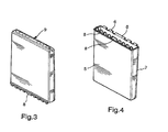
- FIGS. 3 and 4 are perspective views of the frame of the lockable container of FIG. 1;
- FIGS. 5 and 6 are perspective views of the closure member of the lockable container of FIG. 1;
- FIGS. 7 and 8 are perspective views of the latch member of the container of FIG. 1;
- FIG. 9 is an exploded view of the lockable container of FIG. 1;
- FIG. 10 is a perspective view of the container of FIG. 9 when assembled, with the closure member in an open position;
- FIGS. 11 and 12 are enlarged partial X-ray views of details of the container of FIG. 10;
- FIG. 13 shows a known magnetic device for releasing the locking member in a container in accordance with the present invention
- FIG. 14 is a perspective view of the frame of the lockable container of FIG. 18;
- FIGS. 15 and 16 are perspective views of the latch member of the lockable container of FIG. 18;
- FIG. 17 is a perspective view of the closure member of the lockable container of FIG. 18;
- FIG. 18 is an exploded view of a lockable container in accordance with a second embodiment of the invention.
- FIG. 19 is a perspective view of the lockable container of FIG. 1 with the frame members in an open configuration
- FIG. 20 is a perspective view, similar to FIG. 19, of a third embodiment of the invention.
- FIG. 21 shows a rubber boot suitable for use with the invention.
- FIG. 22 illustrates releasable sealing of the frame of the lockable container of FIG. 18 by the rubber boot, in accordance with a further embodiment of the invention.
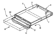
- the display container comprises a tough, transparent frame 2 , for example of polycarbonate, a closure member 10 and a latch member 28 .
- the frame 2 is in this example a generally parallelepiped box having an elongate access opening 4 along one face.
- the frame 2 is dimensioned so that a DVD box 3 , shown in broken lines in FIG. 1, is a sliding fit within the container.
- the frame 2 is formed from a first frame member 5 and a second frame member 7 , each of which is provided with integral hinge members 11 that co-operate to form a hinge housing that receives a hinge pin (not shown) in a manner known per se to provide a hinge 9 .
- the box 3 is fully inserted into the frame 2 in the direction of the arrow A.
- the frame 2 could of course be adjusted to the open configuration to receive the DVD box and then adjusted back to the closed configuration.
- the frame is pivoted about a hinge in the direction of the arrow B so that its access opening 4 is covered by the closure member 10 .
- the elongate latch member 28 is pushed axially in the direction of arrow C to lock the closure member 10 to the frame 2 as will be explained below.
- the frame 2 has hinge members 6 along one long edge of the access opening 4 , and a plurality of generally L-shaped detent members 8 formed along the opposed edge, as best shown in FIG. 4.
- the closure member 10 has hinge members 12 along one long edge, as best shown in FIG. 6.
- the respective hinge members 6 , 12 butt together side by side to form a pair of hinge housings having blind tubular bores into each of which is inserted a hinge pin 14 .
- the hinge pin 14 is a close fit for the insides of the hinge members 6 , 12 and, once inserted, cannot be removed without breaking the container.
- the latch member 28 is slidably housed in the closure member 10 , retained by tabs 18 on the closure member 10 . At one end of the latch member 28 is a blind bore 30 for receiving a spring 26 . When the latch member 2 B is housed in the closure member 10 , the spring 26 biases the latch member to the right as shown in FIG. 10.
- the closure member 10 has a blind bore 16 and the latch member 28 has a blind bore 32 .
- a magnetically movable pin 22 sits in the bore 16 on the closure member, biased towards the latch member 28 by a spring 24 . if the latch member is pushed to the left as shown in FIG. 10, for example by the action of a user's finger on a nub 36 which projects through an aperture 20 in the closure member, the bores 16 , 32 move into register and the pin 22 is urged transversely to locate in the bore 32 in the latch member thereby preventing axial movement of the latch member.
- the closure member 10 is pivoted about the hinge members 6 , 12 , with the latch member 28 in the unlatched position so that the closure member 10 completely blocks the access opening 4 .
- the tabs 18 on the closure member and the detents 34 on the latch member are disposed in spaces adjacent to the detents 8 on the frame 2 .
- the user pushes the nub 36 until the pin 22 engages in the latch member 28 as described above, thereby locking the latch member and preventing sliding movement of the latch member.
- the detents 34 on the latch member 28 engage with the detents 8 on the frame 2 , thereby preventing pivoting of the closure member 10 away from the blocking position.
- a known magnetic release device 38 (FIG. 13) is used by the sales person.
- the magnetic release device 38 comprises a base plate 40 having screw holes 42 by which it is secured to a work surface (not shown).
- the base plate 40 carries a circular magnet 44 having a transverse diametric groove 46 cut in it.
- the magnet 44 pulls the locking pin 22 to cause the pin 22 to withdraw fully from the bore 32 in the latch member 28 .
- the spring 26 pushes the latch member 28 to the unlatched position, allowing the container to be opened by pivoting of the closure member from the blocking position.
- the first frame member 5 has been made deeper, while the second frame member 7 and the closure member 10 and latch member 28 are identical to those described above.
- the container can accommodate deeper DVD boxes or boxes with bulky packaging. With the frame members in the closed configuration, locking and unlocking are achieved as described with reference to the embodiment of FIG. 19.
- the closure member 10 is fully detachable from the frame.
- the access opening on the frame is provided with a further set of detent members 8 , the two sets of detent members being on opposed edges.
- a corresponding further set of tabs 18 is provided on the closure member 10
- a corresponding further set of detents 34 are provided on the latch member 28 .
- Any or all of the latch member 28 , the closure member 10 and the frame 2 may be constructed to have a plane of symmetry.
- the hinged frame is pivoted to the closed configuration so that the first frame member 5 and the second frame member 7 co-operate to define a frame with a rectangular access opening.
- the detents 8 on the frame are inserted into the spaces beside the tabs 18 on the closure member. Adjustment of the latch member 28 to the latched position then causes both sets of detents 34 on the latch member to engage with both sets of detents 8 on the frame, while remaining engaged with the corresponding tabs on the closure member.
- the closure member 10 is thereby securely locked to the frame along both long edges of the access opening. Unlocking is achieved by adjusting the latch member back to the unlatched position, after withdrawal of the locking pin by a suitable magnet. The closure member may then be removed from the frame.
- the product need not be removed from the frame 2 .
- the lockable closure member 10 may be replaced by a rubber boot 13 which protects the contents of the container from the environment and inhibits the contents from accidentally falling out.
- the rubber boot 13 may readily be removed by the customer.
- the security case may therefore be transformed into a rental case
Landscapes
- Engineering & Computer Science (AREA)
- Multimedia (AREA)
- Closures For Containers (AREA)
Abstract
A lockable container for a DVD box or the like comprises a frame and a closure member. The frame is formed from a first frame member and a second frame member which are hingedly connected together and pivotable between an open configuration and a closed configuration. In the closed configuration the frame members co-operate to define an access opening whereby an article may be inserted into or removed from the frame. The article may alternatively pass through a larger opening with the frame members in the open configuration. The closure member is lockable on the frame when the frame members are in the closed configuration so as to substantially block the access opening and prevent adjustment of the frame members from the closed configuration.
Description
- The present invention relates to a lockable container, notably a lockable container for displaying pre-recorded storage media such as digital versatile discs (DVDs), video cassettes or compact discs (CDs).
- Pre-recorded storage media such as CDs and video cassettes are usually put up for sale in a plastic case or the like, which carries information about the disc or tape as well as carrying sales promotional material or artwork to attract a purchaser. To prevent theft of the media from a shop various lockable display containers have been proposed which house the disc or tape in its case and prevent a thief gaining access to the disc or tape without breaking the container or removing the container from the shop. The container can be fitted with alarm means so that it cannot be removed from the shop without actuating an alarm. Examples of prior art lockable containers are described in EP 0 312 172, EP 0 541 733, EP 0 666 954, and WO95/14841 .
- WO 00/61899, the contents of which are incorporated herein by reference, describes a lockable container comprising a frame which has an access opening, a closure member pivotally mounted over the opening, and a latch member which is axially movable within the closure member. The latch member and the frame are each provided with interengageable detents, engagement of which prevents pivoting of the closure member when the latch member is in a latched position. The latch member can be locked in the latched position, thereby locking the closure member over the opening of the container.
- The present invention seeks to provide an improved lockable container for DVDs and other valuable items.
- According to an aspect of the present invention there is provided a lockable container comprising:
- a frame comprising a first frame member and a second frame member which are pivotally connected together and adjustable between an open configuration and a closed configuration, the two frame members in the closed configuration defining an access opening therebetween;
- and a closure member adapted to be mounted on the frame in a blocking position over the access opening so as to block substantially all of the access opening and retain the frame members in the closed configuration, the closure member housing an elongate latch member which is axially movable between a latched position and an unlatched position; wherein
- the latch member and the closure member are each provided with at least one engagement feature, the said features being interengaged when the latch member is in the latched position, and
- the latch member and the frame are each provided with at least one engagement feature, the said features being interengaged when the latch member is adjusted to the latched position while the closure member is in the blocking position, and disengaged when the latch member is in the unlatched position;
- whereby when the closure member is in the blocking position movement of the latch member from the unlatched position to the latched position prevents movement of the closure member from the blocking position; movement of the latch member to the unlatched position causing it to disengage from the frame and permit movement of the closure member to unblock the access opening and permit pivoting of the frame members to the open configuration;
- the closure member being provided with a locking member adjustable between a locked position at which it engages the latch member in the latched position so as to retain the latch member against axial movement, and an unlocked position at which the locking member permits axial movement of the latch member.
- The container of the invention is of particular use for storing and displaying DVDs and other media which are fragile or which have frangible or scratchable cases. The frame preferably comprises two rectangular or square flat sides and four narrow sides, one of which provides the access opening.
- Forming the frame from two frame members permits one frame member to be varied in size to facilitate the accommodation of oversized packaging, while the remaining components stay unchanged. In this way a new container design may be produced very quickly and inexpensively in response to new products coming onto the market. Articles may be inserted into and removed from the frame either through the access opening or by opening the frame up to the open configuration. The latter route is essential if the article is too big to fit through the access opening, and it may also be desirable if the article or its packaging is a tight fit in the access opening, to increase packing or unpacking speed or to prevent scuffing.
- The closure member may be pivotally connected to the frame on one edge, for example as described in WO 00/61899. In this embodiment the engagement between the frame and the latch member is most effectively provided at or adjacent an opposed edge of the frame. Alternatively, the closure member may be removable from the frame. In this embodiment, the latch member may engage with two different edges, notably two opposed edges, of the frame. The provision of a removable closure member provides a number of advantages. Because hinge pins are not required between the closure member and the frame the container is lighter, slimmer and cheaper to manufacture. Storage of unused containers will take up less space. By replacing the removed closure member with a removable cap, for example a rubber boot, the container may be transformed into a rental case that a customer could take the product home in, thereby obviating the need for two separate containers. The invention therefore also provides a lockable container system comprising a lockable container as described, wherein the closure member is removable from the frame, and a releasable cover for fitting on the frame when the closure member is removed.
- In a preferred embodiment, each engagement feature on the latch member engages with an engagement feature on the frame and on the closure member when the container is locked, to provide a secure closure. For increased security it is preferred that a plurality of engagement features are provided on the latch member and correspondingly on the frame and closure members.
- The latch member may be of unitary construction for simplicity of manufacture. It may be moved to the latched position by pushing with a user's finger.
- The frame could be a skeletal frame, but it is preferred that it has no openings other than the access opening when the frame members are in the closed configuration, so that an article contained within the frame cannot be tampered with when the closure member is in the blocking position.
- In a preferred embodiment, the latch member is biased to either the latched or the unlatched position by spring means. To facilitate opening of the container, it is preferred that the latch member is biased to the unlatched position, So that when the locking member is moved to the unlocked position the latch member moves to the unlatched position.
- As known per se, the interior of the container may be provided with an electronic tag which activates an alarm system if the container is removed without proper authorisation.
- Other aspects and benefits of the invention will appear in the following specification, drawings and claims.
- The invention will now be further described, by way of example, with reference to the following drawings in which:
- FIG. 1 is a perspective view of a lockable container for display of a DVD case in accordance with one embodiment of the present invention;
- FIG. 2 is a perspective view of the lockable container of FIG. 1 in a locked state;
- FIGS. 3 and 4 are perspective views of the frame of the lockable container of FIG. 1;
- FIGS. 5 and 6 are perspective views of the closure member of the lockable container of FIG. 1;
- FIGS. 7 and 8 are perspective views of the latch member of the container of FIG. 1;
- FIG. 9 is an exploded view of the lockable container of FIG. 1;
- FIG. 10 is a perspective view of the container of FIG. 9 when assembled, with the closure member in an open position;
- FIGS. 11 and 12 are enlarged partial X-ray views of details of the container of FIG. 10;
- FIG. 13 shows a known magnetic device for releasing the locking member in a container in accordance with the present invention;
- FIG. 14 is a perspective view of the frame of the lockable container of FIG. 18;
- FIGS. 15 and 16 are perspective views of the latch member of the lockable container of FIG. 18;
- FIG. 17 is a perspective view of the closure member of the lockable container of FIG. 18;
- FIG. 18 is an exploded view of a lockable container in accordance with a second embodiment of the invention;
- FIG. 19 is a perspective view of the lockable container of FIG. 1 with the frame members in an open configuration;
- FIG. 20 is a perspective view, similar to FIG. 19, of a third embodiment of the invention;
- FIG. 21 shows a rubber boot suitable for use with the invention; and
- FIG. 22 illustrates releasable sealing of the frame of the lockable container of FIG. 18 by the rubber boot, in accordance with a further embodiment of the invention.
- The display container comprises a tough,
transparent frame 2, for example of polycarbonate, aclosure member 10 and alatch member 28. - The
frame 2 is in this example a generally parallelepiped box having an elongate access opening 4 along one face. Theframe 2 is dimensioned so that aDVD box 3, shown in broken lines in FIG. 1, is a sliding fit within the container. Theframe 2 is formed from afirst frame member 5 and asecond frame member 7, each of which is provided withintegral hinge members 11 that co-operate to form a hinge housing that receives a hinge pin (not shown) in a manner known per se to provide ahinge 9. By pivoting the frame members about thehinge 9 they may be adjusted between an open configuration as shown in FIG. 19 and a closed configuration as shown in FIG. 1. In the closed configuration the frame members are butted together and co-operate to define the access opening 4. - To lock the
DVD box 3 in the container, thebox 3 is fully inserted into theframe 2 in the direction of the arrow A. Alternatively, theframe 2 could of course be adjusted to the open configuration to receive the DVD box and then adjusted back to the closed configuration. After the DVD box is in the frame, the frame is pivoted about a hinge in the direction of the arrow B so that its access opening 4 is covered by theclosure member 10. Finally, theelongate latch member 28 is pushed axially in the direction of arrow C to lock theclosure member 10 to theframe 2 as will be explained below. - The
frame 2 hashinge members 6 along one long edge of the access opening 4, and a plurality of generally L-shapeddetent members 8 formed along the opposed edge, as best shown in FIG. 4. Theclosure member 10 hashinge members 12 along one long edge, as best shown in FIG. 6. Therespective hinge members hinge pin 14. Thehinge pin 14 is a close fit for the insides of thehinge members - The
latch member 28 is slidably housed in theclosure member 10, retained bytabs 18 on theclosure member 10. At one end of thelatch member 28 is ablind bore 30 for receiving aspring 26. When the latch member 2B is housed in theclosure member 10, thespring 26 biases the latch member to the right as shown in FIG. 10. - The
closure member 10 has ablind bore 16 and thelatch member 28 has ablind bore 32. A magneticallymovable pin 22 sits in thebore 16 on the closure member, biased towards thelatch member 28 by aspring 24. if the latch member is pushed to the left as shown in FIG. 10, for example by the action of a user's finger on a nub 36 which projects through anaperture 20 in the closure member, thebores pin 22 is urged transversely to locate in thebore 32 in the latch member thereby preventing axial movement of the latch member. - To protect an article in the
frame 2, theclosure member 10 is pivoted about thehinge members latch member 28 in the unlatched position so that theclosure member 10 completely blocks the access opening 4. In this closed position, thetabs 18 on the closure member and thedetents 34 on the latch member are disposed in spaces adjacent to thedetents 8 on theframe 2. The user pushes thenub 36 until thepin 22 engages in thelatch member 28 as described above, thereby locking the latch member and preventing sliding movement of the latch member. In this position, thedetents 34 on thelatch member 28 engage with thedetents 8 on theframe 2, thereby preventing pivoting of theclosure member 10 away from the blocking position. - To open the container, a known magnetic release device 38 (FIG. 13) is used by the sales person. The
magnetic release device 38 comprises abase plate 40 having screw holes 42 by which it is secured to a work surface (not shown). Thebase plate 40 carries acircular magnet 44 having a transversediametric groove 46 cut in it. When theclosure member 10 is inserted into thegroove 46 themagnet 44 pulls the lockingpin 22 to cause thepin 22 to withdraw fully from thebore 32 in thelatch member 28. Thespring 26 pushes thelatch member 28 to the unlatched position, allowing the container to be opened by pivoting of the closure member from the blocking position. - Referring now to FIG. 20, the
first frame member 5 has been made deeper, while thesecond frame member 7 and theclosure member 10 andlatch member 28 are identical to those described above. The container can accommodate deeper DVD boxes or boxes with bulky packaging. With the frame members in the closed configuration, locking and unlocking are achieved as described with reference to the embodiment of FIG. 19. - Referring now to FIGS. 14 to 18, another embodiment is illustrated Here, the
closure member 10 is fully detachable from the frame. The access opening on the frame is provided with a further set ofdetent members 8, the two sets of detent members being on opposed edges. A corresponding further set oftabs 18 is provided on theclosure member 10, and a corresponding further set ofdetents 34 are provided on thelatch member 28. Any or all of thelatch member 28, theclosure member 10 and theframe 2 may be constructed to have a plane of symmetry. To lock the container, the hinged frame is pivoted to the closed configuration so that thefirst frame member 5 and thesecond frame member 7 co-operate to define a frame with a rectangular access opening. With thelatch member 28 housed in the unlatched position in theclosure member 10, thedetents 8 on the frame are inserted into the spaces beside thetabs 18 on the closure member. Adjustment of thelatch member 28 to the latched position then causes both sets ofdetents 34 on the latch member to engage with both sets ofdetents 8 on the frame, while remaining engaged with the corresponding tabs on the closure member. Theclosure member 10 is thereby securely locked to the frame along both long edges of the access opening. Unlocking is achieved by adjusting the latch member back to the unlatched position, after withdrawal of the locking pin by a suitable magnet. The closure member may then be removed from the frame. - As illustrated in FIGS. 21 and 22, the product need not be removed from the
frame 2. When the container is used with a rented item, for example a DVD, thelockable closure member 10 may be replaced by arubber boot 13 which protects the contents of the container from the environment and inhibits the contents from accidentally falling out. Therubber boot 13 may readily be removed by the customer. The security case may therefore be transformed into a rental case - It is appreciated that certain features of the invention, which are, for clarity, described in the context of separate embodiments, may also be provided in combination in a single embodiment. Conversely, various features of the invention which are, for brevity, described in the context of a single embodiment, may also be provided separately, or in any suitable combination.
- While the present invention has been described with reference to specific embodiments, it should be understood that modifications and variations of the invention may be constructed without departing from the spirit and scope of the invention.
Claims (20)
1. A lockable container comprising:
a frame comprising a first frame member and a second frame member which are pivotally connected together and adjustable between an open configuration and a closed configuration, the two frame members in the closed configuration defining an access opening therebetween;
and a closure member adapted to be mounted on the frame in a blocking position over the access opening so as to block substantially all of the access opening and retain the frame members in the closed configuration, the closure member housing an elongate latch member which is axially movable between a latched position and an unlatched position; wherein
the latch member and the closure member are each provided with at least one engagement feature, the said features being interengaged when the latch member is in the latched position, and
the latch member and the frame are each provided with at least one engagement feature, the said features being interengaged when the latch member is adjusted to the latched position while the closure member is in the blocking position, and disengaged when the latch member is in the unlatched position;
whereby when the closure member is in the blocking position movement of the latch member from the unlatched position to the latched position prevents movement of the closure member from the blocking position; movement of the latch member to the unlatched position causing it to disengage from the frame and permit movement of the closure member to unblock the access opening and permit pivoting of the frame members to the open configuration;
the closure member being provided with a locking member adjustable between a locked position at which it engages the latch member in the latched position so as to retain the latch member against axial movement, and an unlocked position at which the locking member permits axial movement of the latch member.
2. A lockable container as claimed in claim 1 , wherein the closure member is removable from the frame.
3. A lockable container as claimed in claim 1 , wherein the closure member and the latch member both have a plane of symmetry
4. A lockable container as claimed in claim 1 , wherein the latch member is provided with a region which is accessible to a user's finger when the latch member is in the unlatched position, whereby pushing on the said region will cause the latch member to move axially to the latched position.
5. A lockable container as claimed in claim 1 , wherein the access opening is the only opening to the inside of the frame when the frame members are in the closed configuration.
6. A lockable container as claimed in claim 2 , wherein the access opening includes two opposed sides and engagement features are provided along both of the said sides for engagement with corresponding engagement features on the latch member.
7. A lockable container as claimed in claim 2 , further comprising a releasable cover for fitting over the access opening of the frame when the closure member is removed from the frame.
8. A lockable container as claimed in claim 7 , wherein the said cover is a rubber boot.
9. A lockable container comprising:
a frame having an access opening;
and a closure member adapted to be mounted on the frame in a blocking position over the access opening so as to block substantially all of the access opening, the closure member housing an elongate latch member which is axially movable between a latched position and an unlatched position; wherein
the latch member and the closure member are each provided with at least one engagement feature, the said features being interengaged when the latch member is in the latched position, and
the latch member and the frame are each provided with at least one engagement feature, the said features being interengaged when the latch member is adjusted to the latched position while the closure member is in the blocking position, and disengaged when the latch member is in the unlatched position;
whereby when the closure member is in the blocking position movement of the latch member from the unlatched position to the latched position prevents movement of the closure member from the blocking position; movement of the latch member to the unlatched position causing it to disengage from the frame and permit the closure member to be removed from the frame;
the closure member being provided with a locking member adjustable between a locked position at which it engages the latch member in the latched position so as to retain the latch member against axial movement, and an unlocked position at which the locking member permits axial movement of the latch member.
10. A lockable container as claimed in claim 9 , wherein the frame comprises a first frame member and a second frame member which are pivotally connected together and adjustable between an open configuration and a closed configuration, the two frame members in the closed configuration butting together and defining the access opening therebetween; whereby locking of the blocking member on the frame over the access opening prevents adjustment of the frame members to the open configuration.
11. A lockable container as claimed in claim 9 , wherein the access opening includes two opposed sides and engagement features are provided along both of the said sides for engagement with corresponding engagement features on the latch member.
12. A lockable container as claimed in claim 9 , wherein the closure member and the latch member both have a plane of symmetry.
13. A lockable container as claimed in claim 12 , wherein the frame has a plane of symmetry.
14. A lockable container as claimed in claim 9 , further comprising a releasable cover for fitting over the access opening of the frame when the closure member is removed from the frame.
15. A lockable container as claimed in claim 14 , wherein the said cover is a rubber boot.
16. A lockable container for a DVD box or the like, the container comprising a frame and a closure member, wherein:
the frame is formed from a first frame member and a second frame member which are hingedly connected together and pivotable between an open configuration and a closed configuration, in which closed configuration the frame members co-operate to define a generally parallelepiped frame structure having a single access opening at one face thereof, whereby a DVD box or the like may be inserted into or removed front the frame either through the access opening with the frame members in the closed configuration or through a larger opening with the frame members in the open configuration; and
the closure member is lockable on the frame when the frame members are in the closed configuration so as to substantially block the access opening and prevent adjustment of the frame members from the closed configuration.
17. A lockable container as claimed in claim 16 , wherein the closure member is removable from the frame.
18. A lockable container as claimed in claim 16 , further comprising a releasable cover for fitting over the access opening of the frame when the closure member is removed from the frame.
19. A lockable container as claimed in claim 14 , wherein the said cover is a rubber boot.
20. A lockable container as claimed in claim 16 , wherein the closure member is lockable by means of a latch member housed therein, which is releasably securable in a position where it engages with both the closure member and the frame.
Priority Applications (3)
| Application Number | Priority Date | Filing Date | Title |
|---|---|---|---|
| US10/126,143 US20030196917A1 (en) | 2002-04-19 | 2002-04-19 | Lockable container |
| AU2003224292A AU2003224292A1 (en) | 2002-04-19 | 2003-04-22 | Lockable container |
| PCT/GB2003/001711 WO2003089744A1 (en) | 2002-04-19 | 2003-04-22 | Lockable container |
Applications Claiming Priority (1)
| Application Number | Priority Date | Filing Date | Title |
|---|---|---|---|
| US10/126,143 US20030196917A1 (en) | 2002-04-19 | 2002-04-19 | Lockable container |
Publications (1)
| Publication Number | Publication Date |
|---|---|
| US20030196917A1 true US20030196917A1 (en) | 2003-10-23 |
Family
ID=29214949
Family Applications (1)
| Application Number | Title | Priority Date | Filing Date |
|---|---|---|---|
| US10/126,143 Abandoned US20030196917A1 (en) | 2002-04-19 | 2002-04-19 | Lockable container |
Country Status (3)
| Country | Link |
|---|---|
| US (1) | US20030196917A1 (en) |
| AU (1) | AU2003224292A1 (en) |
| WO (1) | WO2003089744A1 (en) |
Cited By (11)
| Publication number | Priority date | Publication date | Assignee | Title |
|---|---|---|---|---|
| US20030116455A1 (en) * | 2001-12-05 | 2003-06-26 | Marsilio Ronald M. | Lockable media storage container |
| US20040020812A1 (en) * | 1998-01-29 | 2004-02-05 | Belden Dennis D. | Lockable media storage box with lock and key |
| US20040084344A1 (en) * | 1998-01-29 | 2004-05-06 | Burdett Ronald K. | Lockable media storage box with lock and key |
| US20040177657A1 (en) * | 2003-03-10 | 2004-09-16 | Jee-Tae Kim | Security device for information storage media |
| US20060042331A1 (en) * | 2004-08-27 | 2006-03-02 | Benda Steven J | Lockbox |
| US20100000890A1 (en) * | 1998-01-29 | 2010-01-07 | Belden Jr Dennis D | Security storage container |
| US20100122986A1 (en) * | 2007-05-03 | 2010-05-20 | Pietro Necchi | Interchangeable closing device for anti-theft case and anti-theft case equipped with such device |
| US7891220B2 (en) * | 2006-01-05 | 2011-02-22 | Sinox Company Ltd. | Multi-purpose detachable lock container and method of use |
| US9370230B1 (en) * | 2014-05-08 | 2016-06-21 | Kar Ming So | Waterproof electronic device holder having rotating and hinged lock |
| USD860181S1 (en) | 2017-01-20 | 2019-09-17 | Steven Wang | Mobile device case |
| US10413028B2 (en) * | 2017-01-20 | 2019-09-17 | Steven Wang | Mobile device case for wet environments |
Citations (7)
| Publication number | Priority date | Publication date | Assignee | Title |
|---|---|---|---|---|
| US5277308A (en) * | 1992-07-10 | 1994-01-11 | Specialty Store Services, Inc. | Transparent display case with resilient long-life hinge |
| US5375708A (en) * | 1994-04-25 | 1994-12-27 | Empak, Inc. | Reusable hard clear package for video games |
| US5454932A (en) * | 1993-09-10 | 1995-10-03 | Trimark Molded Products, Inc. | Cassette display case |
| US5517178A (en) * | 1992-11-06 | 1996-05-14 | Power Systems Industria E Comercio Representacoes Ltda. | Anti-theft package |
| US5598728A (en) * | 1995-03-03 | 1997-02-04 | Autronic Plastics, Inc. | Security case |
| US6240750B1 (en) * | 1999-07-15 | 2001-06-05 | Geoffrey Inc. | Security case |
| US20020003095A1 (en) * | 2000-05-03 | 2002-01-10 | Jaeb Michael S. | Security box for recorded media |
Family Cites Families (5)
| Publication number | Priority date | Publication date | Assignee | Title |
|---|---|---|---|---|
| US5375712A (en) * | 1992-09-25 | 1994-12-27 | Alpha Enterprises, Inc. | Security container with a key |
| ATE166691T1 (en) * | 1993-03-17 | 1998-06-15 | Pataco Ag | ANTI-THEFT DEVICE |
| NL1000905C2 (en) * | 1995-07-31 | 1997-02-04 | Hulsegge Int Bv | Theft-proof container. |
| WO2000053873A1 (en) * | 1999-03-09 | 2000-09-14 | Alpha Enterprises, Inc. | Adapter for security package |
| GB9908080D0 (en) * | 1999-04-09 | 1999-06-02 | Broadhead Robert M | Apparatus |
-
2002
- 2002-04-19 US US10/126,143 patent/US20030196917A1/en not_active Abandoned
-
2003
- 2003-04-22 WO PCT/GB2003/001711 patent/WO2003089744A1/en not_active Ceased
- 2003-04-22 AU AU2003224292A patent/AU2003224292A1/en not_active Abandoned
Patent Citations (7)
| Publication number | Priority date | Publication date | Assignee | Title |
|---|---|---|---|---|
| US5277308A (en) * | 1992-07-10 | 1994-01-11 | Specialty Store Services, Inc. | Transparent display case with resilient long-life hinge |
| US5517178A (en) * | 1992-11-06 | 1996-05-14 | Power Systems Industria E Comercio Representacoes Ltda. | Anti-theft package |
| US5454932A (en) * | 1993-09-10 | 1995-10-03 | Trimark Molded Products, Inc. | Cassette display case |
| US5375708A (en) * | 1994-04-25 | 1994-12-27 | Empak, Inc. | Reusable hard clear package for video games |
| US5598728A (en) * | 1995-03-03 | 1997-02-04 | Autronic Plastics, Inc. | Security case |
| US6240750B1 (en) * | 1999-07-15 | 2001-06-05 | Geoffrey Inc. | Security case |
| US20020003095A1 (en) * | 2000-05-03 | 2002-01-10 | Jaeb Michael S. | Security box for recorded media |
Cited By (16)
| Publication number | Priority date | Publication date | Assignee | Title |
|---|---|---|---|---|
| US20100000890A1 (en) * | 1998-01-29 | 2010-01-07 | Belden Jr Dennis D | Security storage container |
| US20040020812A1 (en) * | 1998-01-29 | 2004-02-05 | Belden Dennis D. | Lockable media storage box with lock and key |
| US20040084344A1 (en) * | 1998-01-29 | 2004-05-06 | Burdett Ronald K. | Lockable media storage box with lock and key |
| US7992711B2 (en) | 1998-01-29 | 2011-08-09 | Autronic Plastics, Inc. | Security storage container |
| US6886691B2 (en) | 1998-01-29 | 2005-05-03 | Nexpak Corporation | Lockable media storage box with lock and key |
| US6966438B2 (en) | 1998-01-29 | 2005-11-22 | Nexpak Corporation | Lockable media storage box with lock and key |
| US20030116455A1 (en) * | 2001-12-05 | 2003-06-26 | Marsilio Ronald M. | Lockable media storage container |
| US6880372B2 (en) * | 2003-03-10 | 2005-04-19 | Kim Jae-Tae | Security device for information storage media |
| US20040177657A1 (en) * | 2003-03-10 | 2004-09-16 | Jee-Tae Kim | Security device for information storage media |
| US20060042331A1 (en) * | 2004-08-27 | 2006-03-02 | Benda Steven J | Lockbox |
| US7891220B2 (en) * | 2006-01-05 | 2011-02-22 | Sinox Company Ltd. | Multi-purpose detachable lock container and method of use |
| US20100122986A1 (en) * | 2007-05-03 | 2010-05-20 | Pietro Necchi | Interchangeable closing device for anti-theft case and anti-theft case equipped with such device |
| US8061514B2 (en) * | 2007-05-03 | 2011-11-22 | Pietro Necchi | Interchangeable closing device for anti-theft case and anti-theft case equipped with such device |
| US9370230B1 (en) * | 2014-05-08 | 2016-06-21 | Kar Ming So | Waterproof electronic device holder having rotating and hinged lock |
| USD860181S1 (en) | 2017-01-20 | 2019-09-17 | Steven Wang | Mobile device case |
| US10413028B2 (en) * | 2017-01-20 | 2019-09-17 | Steven Wang | Mobile device case for wet environments |
Also Published As
| Publication number | Publication date |
|---|---|
| WO2003089744A1 (en) | 2003-10-30 |
| AU2003224292A1 (en) | 2003-11-03 |
Similar Documents
| Publication | Publication Date | Title |
|---|---|---|
| US8016147B2 (en) | Lockable container with improved slide latch and lock | |
| US5297672A (en) | Security package for compact discs | |
| CA2063534C (en) | Cassette security container | |
| US7614265B2 (en) | Lockable storage container | |
| US6676175B2 (en) | Security box for recorded media | |
| US6125668A (en) | Recorded media security container | |
| US5797487A (en) | Lockable compact disk storage apparatus | |
| AU727552B2 (en) | Security container | |
| US5417319A (en) | Security container for display of audio and video media | |
| EP1463866B1 (en) | Lockable media storage container | |
| US20030000852A1 (en) | Lockable box | |
| WO1993015294A1 (en) | Stock protection device | |
| US20030196917A1 (en) | Lockable container | |
| US7526931B2 (en) | Security device for media case and method | |
| US20030000853A1 (en) | Lockable box | |
| US20050082183A1 (en) | Standardized disc container with added security feature | |
| MXPA05007581A (en) | Safety device for containers storing recording means, having an improved closing member. |
Legal Events
| Date | Code | Title | Description |
|---|---|---|---|
| AS | Assignment |
Owner name: 5,147,034, LLC, WISCONSIN Free format text: ASSIGNMENT OF ASSIGNORS INTEREST;ASSIGNOR:BROADHEAD, ROBERT M.;REEL/FRAME:014235/0186 Effective date: 20030605 |
|
| STCB | Information on status: application discontinuation |
Free format text: ABANDONED -- FAILURE TO RESPOND TO AN OFFICE ACTION |