US20030196821A1 - Cover assembly for a concealed sprinkler head - Google Patents
Cover assembly for a concealed sprinkler head Download PDFInfo
- Publication number
- US20030196821A1 US20030196821A1 US10/379,546 US37954603A US2003196821A1 US 20030196821 A1 US20030196821 A1 US 20030196821A1 US 37954603 A US37954603 A US 37954603A US 2003196821 A1 US2003196821 A1 US 2003196821A1
- Authority
- US
- United States
- Prior art keywords
- cover assembly
- layer
- tabs
- insulative
- metallic
- Prior art date
- Legal status (The legal status is an assumption and is not a legal conclusion. Google has not performed a legal analysis and makes no representation as to the accuracy of the status listed.)
- Granted
Links
Images


Classifications
-
- A—HUMAN NECESSITIES
- A62—LIFE-SAVING; FIRE-FIGHTING
- A62C—FIRE-FIGHTING
- A62C37/00—Control of fire-fighting equipment
- A62C37/08—Control of fire-fighting equipment comprising an outlet device containing a sensor, or itself being the sensor, i.e. self-contained sprinklers
- A62C37/09—Control of fire-fighting equipment comprising an outlet device containing a sensor, or itself being the sensor, i.e. self-contained sprinklers telescopic or adjustable
Definitions
- the present invention relates generally to automatic sprinkler heads and more particularly, to a decorative cover assembly adapted to conceal a pendent sprinkler head within the ceiling of a fire protected enclosure.
- Sprinkler systems are used extensively to provide automatic fire protection for residential, commercial and public buildings.
- pendent sprinkler heads for ceiling applications, one referred to by the term “concealed” and the other referred to by the term “flush”.
- a concealed sprinkler head has its entire body located above the lower surface of the ceiling of an enclosure in which it is installed.
- a flush sprinkler head has the majority of its body located above the lower surface of the ceiling, but a thermally responsive element and its related elements are partly or wholly located below the ceiling.
- the concealed sprinkler head is less obstructive and more aesthetical than the flush sprinkler head.
- U.S. Pat. No. 4,014,388 issued to Anderson discloses a concealed sprinkler head wherein a cylindrical housing is located above the ceiling of a fire protected enclosure and surrounds a thermally responsive element and all the other operative parts.
- a metallic cover plate is connected to the cylindrical housing through a metallic connecter ring and mounted flush against the ceiling so that none of the operative parts is visible.
- Solder is used to attach the metallic connector plate to the metallic connector ring.
- U.S. Pat. No. 4,105,076 issued to Simons discloses a sleeve adapted to connect a cover plate to a cylindrical housing and made of a thermosetting resin or other heat insulating material.
- the sleeve has feet around which metal rings fit.
- the metal rings are attached to the cover plate by means of solder.
- the heat insulating material reduces the rate of heat transfer from the cover plate to the housing and facilitates melting of the solder.
- such a resinous sleeve is not durable.
- a concealed sprinkler head is mounted above the ceiling of a fire protected enclosure.
- the concealed sprinkler head includes a housing within which a valve and other operative parts are contained.
- a decorative cover assembly is secured to the housing to conceal the sprinkler head within the ceiling so that none of the operative parts is visible.
- the decorative cover assembly includes a metallic cover plate made of a heat conductive material such as copper and copper alloy, and a metallic skirt including a substantially cylindrical wall, an annular flange extending outwardly from one end of the cylindrical wall, and a plurality of tabs extending generally downwardly from the flange.
- the cylindrical wall of the skirt is threaded on the cylindrical housing of the sprinkler head.
- a plurality of heat insulative elements are disposed between the tabs and the cover plate.
- the upper surface of each of the insulative elements is adhesively attached or otherwise secured to a corresponding one of the tabs.
- a metallic layer is attached to the lower surface of the insulative element.
- a layer of low melting point fusible material or alloy is disposed between the metallic layer and the cover plate. Upon application of heat, the insulative element is secured to the cover plate through the metallic layer.
- the upper surface of the insulative elements may be secured to the tabs in a manner identical to the manner in which the lower surface of the insulative elements is secured to the tabs.
- a second metallic layer is attached to the upper surface of each of the insulative elements, and a second layer of low melting point fusible material or alloy is disposed between the second metallic layer and each of the tabs.
- a protective layer made of a water resistant material such as wax, may surround the layers of fusible alloy, the metallic layers, the insulative elements and the tabs to prevent corrosion of the elements of the decorative cover assembly.
- each of the tabs has a substantially vertical leg, and a foot extending outwardly from the lower end of the leg.
- Each of the insulative elements includes a rectangular plate and opposite side walls extending upwardly from opposite sides of the plate. The insulative element defines a space between the plate and the side walls to receive the foot of the tab.
- the foot of the tab has a recess
- the insulative element includes a plate and a projection formed on the plate. The projection is engageably received within the recess to secure the insulative element to the tab.
- the foot of the tab has a circular opening.
- the insulative element includes a cylindrical shank and a head connected to one end of the shank.
- the shank is snugly fit in the opening to secure the insulative element to the tab.
- the insulative element may alternatively include a round base, and a semispherical head connected to the base with a diametrical slit. The semispherical head is inserted through the opening to secure the insulative element to the tab.
- the cover plate may partly or wholly be made of a shape-memory alloy so that its peripheral edge may be bent in a downward direction when the ambient temperature reaches a predetermined level in the event of a fire.
- a plurality of ribs may be formed in one side of the cover plate.
- FIG. 1 is a vertical sectional view of a concealed sprinkler head mounted above the ceiling of a room and covered by a decorative cover assembly made according to one embodiment of the present invention
- FIG. 2 is a bottom view of the sprinkler head with a cover plate removed for clarity;
- FIG. 3 is an enlarged section, in part, of the decorative cover assembly shown in FIG. 1;
- FIG. 4 is an enlarged perspective view, partly broken away, of the decorative cover assembly shown in FIG. 1;
- FIG. 5 shows the manner in which the cover plate is released from the rest of the decorative cover assembly in the event of a fire
- FIG. 6 is a view similar to that of FIG. 3, but showing a modified form of the decorative cover assembly
- FIG. 7 is an enlarged perspective view, partly broken away, of the decorative cover assembly shown in FIG. 6;
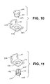
- FIGS. 8 to 11 are perspective fragmentary views of further modified forms of the decorative cover assembly according to the present invention.
- FIG. 1 there is illustrated a concealed sprinkler head, generally designated by the reference numeral 10 , mounted in a hole 12 in the ceiling of a room such that the bottom of the sprinkler head is substantially flush with the ceiling.
- the sprinkler head 10 includes a vertically extending tubular body 14 with a threaded upper or inlet end 14 a adapted to be connected to a water line 16 , and a lower or outlet end 14 b .
- the water line 16 is communicated with a supply of pressurized water or other fire extinguishing fluid (not shown).
- An internal passage 14 c is defined in the tubular body 14 and extends between the inlet end 14 a and the outlet end 14 b .
- An annular flange 18 extends around the outer periphery of the tubular body 14 and is located midway between the inlet end 14 a and the outlet end 14 b .
- a generally cylindrical housing 0 . 20 depends from the annular flange 18 .
- a generally cylindrical casing 22 is secured around the lower end of the tubular body 14 and is located within the housing 20 .
- the outlet end 14 b of the tubular body 14 is normally closed by a valve assembly 24 .
- the valve assembly 24 includes a valve element 26 normally seated on the outlet end 14 b of the tubular body 14 , and a valve holder 28 configured to hold the valve element 26 .
- a deflector assembly 30 and a thermally responsive assembly 32 are operatively associated to normally urge the valve element 26 in its closed position.
- the deflector assembly 30 includes a deflector holder 34 located immediately below the valve assembly 24 and shaped to receive the valve holder 28 .
- a deflector 36 is secured to the deflector holder 34 .
- an upper heat collector element or disk 38 is secured to the bottom of the deflector holder 34 . As shown better in FIG.
- the deflector 36 includes a plurality of tines 40 to alters the trajectory of water in an optimum pattern when the water is discharged from the outlet end 14 b of the tubular body 14 .
- a pair of diametrically opposite struts 42 are connected at their lower end to the deflector 36 and at their upper end to a guide ring 44 .
- the guide ring 44 is slidably moved within the housing 20 .
- a compression spring 46 is disposed between the lower surface of the flange 18 and the upper surface of the guide ring 44 .
- the thermally responsive assembly 32 includes a fuse holder 47 secured to the valve holder 28 and adapted to hold a fusible alloy 48 therewithin.
- the fusible alloy 48 has a melting point of from 70° C. to 90° C.
- a lower heat collector disk 50 is secured to the bottom of the fuse holder 47 .
- An annular ring 52 is located within the casing 22 and disposed between the valve holder 28 and the deflector holder 34
- a decorative cover assembly designated generally by the reference numeral 60 , is secured to the housing 20 to conceal the sprinkler head 10 within the ceiling.
- the decorative cover assembly 60 includes an annular skirt 62 secured around the housing 20 and a generally circular, thin cover plate 64 secured to the skirt 62 .
- the skirt 62 has a helically corrugated cylindrical wall 62 a and an annular flange 62 b extending outwardly from the lower end of the cylindrical wall 62 a .
- the skirt 62 is vertically adjustable by rotation of the skirt 62 relative to the housing 20 .
- the housing 20 is formed on its outer peripheral surface with a plurality of conical projections 66 for engagement with the corrugated cylindrical wall 62 a of the skirt 62 .
- the conical projections 66 are arranged on a helical path around the circumference of the housing 20 .
- the skirt 62 is threaded on the housing 20 until the flange 62 b of the skirt 62 comes into engagement with the ceiling.
- each of the tabs 68 extend downwardly from the flange 62 b and are spaced 120 degrees about the circumference of the flange 62 b .
- Each of the tabs 68 has a substantially L-shape and includes a short leg 68 a and a foot 68 b extending radially outwardly from the lower end of the leg 68 a .
- Three insulative elements 70 are disposed between the corresponding tabs 68 and the cover plate 64 . More specifically, each of the insulative elements 70 is adhesively attached or otherwise secured to the lower surface of the foot 68 b of each tab 68 .
- the insulative element 70 has a thickness of approximately 1.0 mm and is made of a material with a low degree of heat conductivity, such as epoxy resin, phenolic resin, polyester resin and acrylic resin.
- a metallic layer 72 is adhesively attached or otherwise secured to the lower surface of the insulative element 70 .
- the metallic layer 72 has a thickness of from 10 to 200 microns and is preferably made of copper or copper alloy to provide good solderability.
- the metallic layer 72 may alternatively be made of brass, bronze, gold, silver, nickel, tin and similar materials.
- the lower surface of the metallic layer 72 is coated first with flux and then, a layer of a low melting point fusible alloy 74 .
- the layer of fusible alloy 74 has a thickness of from 20 to 200 microns and has a melting point of from 45° C. to 65° C. To ensure melting of the fusible alloy 74 before the fusible alloy 48 of the thermally responsive assembly 32 melts, the fusible alloy 74 should preferably have a lower melting point than the fusible alloy 48 of the thermally responsive assembly 32 .
- the metallic layer 72 is soldered to the cover plate 64 .
- the cover plate 64 is preferably made of copper, aluminum and similar materials to provide a high degree of heat conductivity. As shown best in FIG.
- a protective layer 76 surrounds the insulative elements 70 , the feet 68 b of the tabs 68 , the metallic layer 72 and the fusible alloy 74 .
- the protective layer 76 is made of wax, fluoroplastic and similar water resistant materials to prevent corrosion.
- the fusible alloy 74 melts. As shown in FIG. 5, this causes the cover plate 64 to be quickly released from the rest of the decorative cover assembly 60 since the use of the insulative elements 70 allows the heat to be focused on the fusible alloy 74 and retards heat transfer from the cover plate 64 to the annular skirt 62 .
- the thermally responsive assembly 32 is exposed to an elevated temperature where the fusible alloy 48 melts. Melting of the fusible alloy 48 causes the compression spring 46 to urge the deflector assembly 30 and thus, the annular ring 52 in a downward direction.
- valve assembly 24 is released from the outlet end 14 b of the tubular body 14 .
- valve assembly 24 With the valve assembly 24 in its open position, water is discharged from the outlet end 14 b of the tubular body 14 . The water then strikes the deflector tines 40 and is deflected outwardly in the desired pattern.
- FIGS. 6 and 7 wherein like elements are given like reference numerals, there is illustrated a modified form of the decorative cover assembly according to the present invention.
- the lower surface of the insulative element 70 is secured to the cover plate 64 in the same manner as in the previous embodiment.
- the upper surface of the insulative embodiment 70 is secured to the corresponding tab 68 in a manner identical to the manner in which the lower surface of the insulative element 70 is secured to the cover plate 64 .
- a metallic layer 76 is attached to the upper surface of the insulative element 70 .
- the metallic layer 76 is preferably made of copper or copper alloy to provide good solderability.
- the upper surface of the metallic layer 76 is coated first with flux and then, a layer of fusible alloy 78 .
- the fusible alloy 74 has a lower melting point than the fusible alloy 78 .
- the fusible alloys 74 , 78 may have the substantially same melting point.
- an insulative element 80 is composed of a rectangular plate 80 a and opposite side walls 80 b extending upwardly from opposite sides of the rectangular plate 80 a .
- the side walls 80 b have an inverted L-shape such that a space 82 is defined between the plate 80 a and the side walls 80 b .
- a tab 84 has a vertical leg 84 a and a generally rectangular foot 84 b extending horizontally from the lower end of the leg 84 a and having a slightly round edge 84 c .
- the foot 84 b is inserted through the space 82 between the side walls 84 b to mount the insulative element 80 to the tab 84 .
- the lower surface of the insulative element 80 is secured to the cover plate (not shown in FIG. 8) in the same manner as in the embodiment shown in FIGS. 1 to 4 .
- an insulative element 90 has a rectangular plate 90 a and a generally triangular projection 90 b formed on the plate 90 a and extending along the length of the plate 90 a .
- a tab 92 has a vertical leg 92 a and a U-shaped foot 92 b extending horizontally from the lower end of the leg 92 a .
- a rectangular recess 92 c is formed in the foot 92 b and has opposite beveled sides 92 d .
- the projection 90 b of the insulative element 90 is inserted into the recess 92 c to mount the insulative element 90 to the tab 92 .
- the lower surface of the insulative element 90 is secured to the cover plate (not shown in FIG. 9) in the same manner as in the embodiment shown in FIGS. 1 to 4 .
- an insulative element 100 is in the form of a bolt and has a cylindrical shank 100 a and a circular flat head 100 b connected to the upper end of the shank 100 a .
- a tab 102 has a vertical leg 102 a and a rectangular foot 102 b extending horizontally from the lower end of the leg 102 a and having a circular opening 102 c .
- the outer diameter of the shank 100 a is slightly greater than the inside diameter of the opening 102 c so that the shank 100 a is snugly fit into the opening 102 c .
- the lower end of the shank 100 a is secured to the cover plate (not shown in FIG. 10) in the same manner as in the embodiment shown in FIGS. 1 to 4 .
- an insulative element 110 is composed of a round base 110 a , and a semispherical head 110 b connected to the round base 110 a through a neck portion 110 c .
- a diametrical slit 110 d is formed in the semispherical head 110 b .
- a tab 112 has a vertical leg 112 a and a rectangular foot 112 b extending horizontally from the lower end of the leg 112 a and having a circular opening 112 c .
- the maximum outer diameter of the semispherical head 110 b is slightly greater than the inside diameter of the opening 112 c .
- the semispherical head 110 b is inserted through the opening 112 c so that the neck portion 110 c is located in the opening 112 c .
- the lower end of the round base 110 a is secured to the cover plate (not shown in FIG. 11) in the same manner as in the embodiment shown in FIGS. 1 to 4 .
- All the insulative elements in the embodiments shown in FIGS. 8 to 11 are made of a material with a low degree of heat conductivity, such as epoxy resin, phenolic resin, polyester resin and acrylic resin.
Landscapes
- Health & Medical Sciences (AREA)
- Public Health (AREA)
- Business, Economics & Management (AREA)
- Emergency Management (AREA)
- Fire-Extinguishing By Fire Departments, And Fire-Extinguishing Equipment And Control Thereof (AREA)
Abstract
Description
- The present invention relates generally to automatic sprinkler heads and more particularly, to a decorative cover assembly adapted to conceal a pendent sprinkler head within the ceiling of a fire protected enclosure.
- Sprinkler systems are used extensively to provide automatic fire protection for residential, commercial and public buildings. There are two types of pendent sprinkler heads for ceiling applications, one referred to by the term “concealed” and the other referred to by the term “flush”. A concealed sprinkler head has its entire body located above the lower surface of the ceiling of an enclosure in which it is installed. A flush sprinkler head has the majority of its body located above the lower surface of the ceiling, but a thermally responsive element and its related elements are partly or wholly located below the ceiling. Thus, the concealed sprinkler head is less obstructive and more aesthetical than the flush sprinkler head.
- U.S. Pat. No. 4,014,388 issued to Anderson discloses a concealed sprinkler head wherein a cylindrical housing is located above the ceiling of a fire protected enclosure and surrounds a thermally responsive element and all the other operative parts. A metallic cover plate is connected to the cylindrical housing through a metallic connecter ring and mounted flush against the ceiling so that none of the operative parts is visible. Solder is used to attach the metallic connector plate to the metallic connector ring. One problem arises with this arrangement. In the event of a fire, heat is readily transferred from the metallic cover plate through the solder to the metallic connector ring. As a result, the solder may not melt as quickly as it should be. This results in a reduction in the response time of the thermally responsive element.
- U.S. Pat. No. 4,105,076 issued to Simons discloses a sleeve adapted to connect a cover plate to a cylindrical housing and made of a thermosetting resin or other heat insulating material. The sleeve has feet around which metal rings fit. The metal rings are attached to the cover plate by means of solder. The heat insulating material reduces the rate of heat transfer from the cover plate to the housing and facilitates melting of the solder. However, such a resinous sleeve is not durable.
- Accordingly, it is an object of the present invention to provide a decorative cover assembly for a concealed sprinkler head, which is durable and can minimize the response time of the sprinkler head.
- A concealed sprinkler head is mounted above the ceiling of a fire protected enclosure. The concealed sprinkler head includes a housing within which a valve and other operative parts are contained. A decorative cover assembly is secured to the housing to conceal the sprinkler head within the ceiling so that none of the operative parts is visible. According to the present invention, the decorative cover assembly includes a metallic cover plate made of a heat conductive material such as copper and copper alloy, and a metallic skirt including a substantially cylindrical wall, an annular flange extending outwardly from one end of the cylindrical wall, and a plurality of tabs extending generally downwardly from the flange. The cylindrical wall of the skirt is threaded on the cylindrical housing of the sprinkler head.
- A plurality of heat insulative elements are disposed between the tabs and the cover plate. The upper surface of each of the insulative elements is adhesively attached or otherwise secured to a corresponding one of the tabs. A metallic layer is attached to the lower surface of the insulative element. A layer of low melting point fusible material or alloy is disposed between the metallic layer and the cover plate. Upon application of heat, the insulative element is secured to the cover plate through the metallic layer. The use of the heat insulative elements allows heat to be focused on the fusible alloy in the vent of a fire and facilitates melting of the fusible alloy and thus, release of the cover plate from the rest of the cover assembly.
- In a preferred embodiment, the upper surface of the insulative elements may be secured to the tabs in a manner identical to the manner in which the lower surface of the insulative elements is secured to the tabs. To this end, a second metallic layer is attached to the upper surface of each of the insulative elements, and a second layer of low melting point fusible material or alloy is disposed between the second metallic layer and each of the tabs. A protective layer, made of a water resistant material such as wax, may surround the layers of fusible alloy, the metallic layers, the insulative elements and the tabs to prevent corrosion of the elements of the decorative cover assembly.
- The upper end of the insulative elements may be secured to the tabs by mechanical means. In one embodiment, each of the tabs has a substantially vertical leg, and a foot extending outwardly from the lower end of the leg. Each of the insulative elements includes a rectangular plate and opposite side walls extending upwardly from opposite sides of the plate. The insulative element defines a space between the plate and the side walls to receive the foot of the tab. As an alternative, the foot of the tab has a recess, and the insulative element includes a plate and a projection formed on the plate. The projection is engageably received within the recess to secure the insulative element to the tab. Still alternatively, the foot of the tab has a circular opening. The insulative element includes a cylindrical shank and a head connected to one end of the shank. The shank is snugly fit in the opening to secure the insulative element to the tab. The insulative element may alternatively include a round base, and a semispherical head connected to the base with a diametrical slit. The semispherical head is inserted through the opening to secure the insulative element to the tab.
- The cover plate may partly or wholly be made of a shape-memory alloy so that its peripheral edge may be bent in a downward direction when the ambient temperature reaches a predetermined level in the event of a fire. To increase the rigidity, a plurality of ribs may be formed in one side of the cover plate.
- The above and other features and advantages of the present invention will become more apparent from a reading of the following detailed description when taken in conjunction with the accompanying drawings, in which:
- FIG. 1 is a vertical sectional view of a concealed sprinkler head mounted above the ceiling of a room and covered by a decorative cover assembly made according to one embodiment of the present invention;
- FIG. 2 is a bottom view of the sprinkler head with a cover plate removed for clarity;
- FIG. 3 is an enlarged section, in part, of the decorative cover assembly shown in FIG. 1;
- FIG. 4 is an enlarged perspective view, partly broken away, of the decorative cover assembly shown in FIG. 1;
- FIG. 5 shows the manner in which the cover plate is released from the rest of the decorative cover assembly in the event of a fire;
- FIG. 6 is a view similar to that of FIG. 3, but showing a modified form of the decorative cover assembly;
- FIG. 7 is an enlarged perspective view, partly broken away, of the decorative cover assembly shown in FIG. 6; and
- FIGS. 8 to 11 are perspective fragmentary views of further modified forms of the decorative cover assembly according to the present invention.
- Referring now to FIG. 1, there is illustrated a concealed sprinkler head, generally designated by the
reference numeral 10, mounted in ahole 12 in the ceiling of a room such that the bottom of the sprinkler head is substantially flush with the ceiling. - In the illustrated embodiment, the
sprinkler head 10 includes a vertically extendingtubular body 14 with a threaded upper or inlet end 14 a adapted to be connected to awater line 16, and a lower or outlet end 14 b. Thewater line 16 is communicated with a supply of pressurized water or other fire extinguishing fluid (not shown). An internal passage 14 c is defined in thetubular body 14 and extends between the inlet end 14 a and the outlet end 14 b. Anannular flange 18 extends around the outer periphery of thetubular body 14 and is located midway between the inlet end 14 a and the outlet end 14 b. A generally cylindrical housing 0.20 depends from theannular flange 18. A generallycylindrical casing 22 is secured around the lower end of thetubular body 14 and is located within thehousing 20. - The outlet end 14 b of the
tubular body 14 is normally closed by avalve assembly 24. Thevalve assembly 24 includes avalve element 26 normally seated on the outlet end 14 b of thetubular body 14, and avalve holder 28 configured to hold thevalve element 26. Adeflector assembly 30 and a thermallyresponsive assembly 32 are operatively associated to normally urge thevalve element 26 in its closed position. Thedeflector assembly 30 includes adeflector holder 34 located immediately below thevalve assembly 24 and shaped to receive thevalve holder 28. Adeflector 36 is secured to thedeflector holder 34. Also, an upper heat collector element ordisk 38 is secured to the bottom of thedeflector holder 34. As shown better in FIG. 2, thedeflector 36 includes a plurality oftines 40 to alters the trajectory of water in an optimum pattern when the water is discharged from the outlet end 14 b of thetubular body 14. A pair of diametrically opposite struts 42 are connected at their lower end to thedeflector 36 and at their upper end to aguide ring 44. Theguide ring 44 is slidably moved within thehousing 20. Acompression spring 46 is disposed between the lower surface of theflange 18 and the upper surface of theguide ring 44. The thermallyresponsive assembly 32 includes afuse holder 47 secured to thevalve holder 28 and adapted to hold afusible alloy 48 therewithin. Thefusible alloy 48 has a melting point of from 70° C. to 90° C. A lowerheat collector disk 50 is secured to the bottom of thefuse holder 47. Anannular ring 52 is located within thecasing 22 and disposed between thevalve holder 28 and thedeflector holder 34. - A decorative cover assembly, designated generally by the
reference numeral 60, is secured to thehousing 20 to conceal thesprinkler head 10 within the ceiling. Illustratively, thedecorative cover assembly 60 includes anannular skirt 62 secured around thehousing 20 and a generally circular,thin cover plate 64 secured to theskirt 62. Theskirt 62 has a helically corrugated cylindrical wall 62 a and anannular flange 62 b extending outwardly from the lower end of the cylindrical wall 62 a. Theskirt 62 is vertically adjustable by rotation of theskirt 62 relative to thehousing 20. To this end, thehousing 20 is formed on its outer peripheral surface with a plurality ofconical projections 66 for engagement with the corrugated cylindrical wall 62 a of theskirt 62. Theconical projections 66 are arranged on a helical path around the circumference of thehousing 20. Theskirt 62 is threaded on thehousing 20 until theflange 62 b of theskirt 62 comes into engagement with the ceiling. - Referring to FIGS. 2 to 4, three
tabs 68 extend downwardly from theflange 62 b and are spaced 120 degrees about the circumference of theflange 62 b. Each of thetabs 68 has a substantially L-shape and includes ashort leg 68 a and afoot 68 b extending radially outwardly from the lower end of theleg 68 a. Threeinsulative elements 70 are disposed between thecorresponding tabs 68 and thecover plate 64. More specifically, each of theinsulative elements 70 is adhesively attached or otherwise secured to the lower surface of thefoot 68 b of eachtab 68. Theinsulative element 70 has a thickness of approximately 1.0 mm and is made of a material with a low degree of heat conductivity, such as epoxy resin, phenolic resin, polyester resin and acrylic resin. A metallic layer 72 is adhesively attached or otherwise secured to the lower surface of theinsulative element 70. The metallic layer 72 has a thickness of from 10 to 200 microns and is preferably made of copper or copper alloy to provide good solderability. The metallic layer 72 may alternatively be made of brass, bronze, gold, silver, nickel, tin and similar materials. The lower surface of the metallic layer 72 is coated first with flux and then, a layer of a low melting point fusible alloy 74. The layer of fusible alloy 74 has a thickness of from 20 to 200 microns and has a melting point of from 45° C. to 65° C. To ensure melting of the fusible alloy 74 before thefusible alloy 48 of the thermallyresponsive assembly 32 melts, the fusible alloy 74 should preferably have a lower melting point than thefusible alloy 48 of the thermallyresponsive assembly 32. Upon application of heat, the metallic layer 72 is soldered to thecover plate 64. Thecover plate 64 is preferably made of copper, aluminum and similar materials to provide a high degree of heat conductivity. As shown best in FIG. 3, aprotective layer 76 surrounds theinsulative elements 70, thefeet 68 b of thetabs 68, the metallic layer 72 and the fusible alloy 74. Theprotective layer 76 is made of wax, fluoroplastic and similar water resistant materials to prevent corrosion. - When the ambient temperature exceeds a predetermined value by the heat from a fire, the fusible alloy 74 melts. As shown in FIG. 5, this causes the
cover plate 64 to be quickly released from the rest of thedecorative cover assembly 60 since the use of theinsulative elements 70 allows the heat to be focused on the fusible alloy 74 and retards heat transfer from thecover plate 64 to theannular skirt 62. Upon release of thecover plate 64, the thermallyresponsive assembly 32 is exposed to an elevated temperature where thefusible alloy 48 melts. Melting of thefusible alloy 48 causes thecompression spring 46 to urge thedeflector assembly 30 and thus, theannular ring 52 in a downward direction. As a result, thevalve assembly 24 is released from the outlet end 14 b of thetubular body 14. With thevalve assembly 24 in its open position, water is discharged from the outlet end 14 b of thetubular body 14. The water then strikes thedeflector tines 40 and is deflected outwardly in the desired pattern. - Referring next to FIGS. 6 and 7 wherein like elements are given like reference numerals, there is illustrated a modified form of the decorative cover assembly according to the present invention. The lower surface of the
insulative element 70 is secured to thecover plate 64 in the same manner as in the previous embodiment. In this alternative embodiment, the upper surface of theinsulative embodiment 70 is secured to the correspondingtab 68 in a manner identical to the manner in which the lower surface of theinsulative element 70 is secured to thecover plate 64. Specifically, ametallic layer 76 is attached to the upper surface of theinsulative element 70. As in the metallic layer 72, themetallic layer 76 is preferably made of copper or copper alloy to provide good solderability. The upper surface of themetallic layer 76 is coated first with flux and then, a layer of fusible alloy 78. The fusible alloy 74 has a lower melting point than the fusible alloy 78. However, the fusible alloys 74, 78 may have the substantially same melting point. Upon melting of the fusible alloy 74, thecover plate 64 is released from the rest of thedecorative cover assembly 60 in the same manner as in the previous embodiment. - The insulative elements may be secured to the corresponding tabs by mechanical means as shown in FIGS. 8 to 11. As shown in FIG. 8, an
insulative element 80 is composed of a rectangular plate 80 a and opposite side walls 80 b extending upwardly from opposite sides of the rectangular plate 80 a. The side walls 80 b have an inverted L-shape such that a space 82 is defined between the plate 80 a and the side walls 80 b. Atab 84 has a vertical leg 84 a and a generally rectangular foot 84 b extending horizontally from the lower end of the leg 84 a and having a slightly round edge 84 c. The foot 84 b is inserted through the space 82 between the side walls 84 b to mount theinsulative element 80 to thetab 84. The lower surface of theinsulative element 80 is secured to the cover plate (not shown in FIG. 8) in the same manner as in the embodiment shown in FIGS. 1 to 4. - In the embodiment shown in FIG. 9, an
insulative element 90 has a rectangular plate 90 a and a generally triangular projection 90 b formed on the plate 90 a and extending along the length of the plate 90 a. A tab 92 has avertical leg 92 a and a U-shaped foot 92 b extending horizontally from the lower end of theleg 92 a. Arectangular recess 92 c is formed in the foot 92 b and has opposite beveledsides 92 d. The projection 90 b of theinsulative element 90 is inserted into therecess 92 c to mount theinsulative element 90 to the tab 92. The lower surface of theinsulative element 90 is secured to the cover plate (not shown in FIG. 9) in the same manner as in the embodiment shown in FIGS. 1 to 4. - Turning to FIG. 10, an
insulative element 100 is in the form of a bolt and has a cylindrical shank 100 a and a circularflat head 100 b connected to the upper end of the shank 100 a. A tab 102 has a vertical leg 102 a and a rectangular foot 102 b extending horizontally from the lower end of the leg 102 a and having a circular opening 102 c. The outer diameter of the shank 100 a is slightly greater than the inside diameter of the opening 102 c so that the shank 100 a is snugly fit into the opening 102 c. The lower end of the shank 100 a is secured to the cover plate (not shown in FIG. 10) in the same manner as in the embodiment shown in FIGS. 1 to 4. - In FIG. 11, an
insulative element 110 is composed of a round base 110 a, and a semispherical head 110 b connected to the round base 110 a through a neck portion 110 c. Adiametrical slit 110 d is formed in the semispherical head 110 b. As in the embodiment shown in FIG. 10, a tab 112 has a vertical leg 112 a and a rectangular foot 112 b extending horizontally from the lower end of the leg 112 a and having acircular opening 112 c. The maximum outer diameter of the semispherical head 110 b is slightly greater than the inside diameter of theopening 112 c. With this arrangement, the semispherical head 110 b is inserted through theopening 112 c so that the neck portion 110 c is located in theopening 112 c. The lower end of the round base 110 a is secured to the cover plate (not shown in FIG. 11) in the same manner as in the embodiment shown in FIGS. 1 to 4. All the insulative elements in the embodiments shown in FIGS. 8 to 11 are made of a material with a low degree of heat conductivity, such as epoxy resin, phenolic resin, polyester resin and acrylic resin. - The present invention has been described with respect to its preferred embodiments, it is to be understood that various modifications and changes may be made without departing from the scope of the invention as defined by the appended claims.
Claims (17)
Applications Claiming Priority (4)
| Application Number | Priority Date | Filing Date | Title |
|---|---|---|---|
| JP59621/2002 | 2002-03-06 | ||
| JP2002059621 | 2002-03-06 | ||
| JP2002276849A JP2003325695A (en) | 2002-03-06 | 2002-09-24 | Sprinkler head cover |
| JP276849/2002 | 2002-09-24 |
Publications (2)
| Publication Number | Publication Date |
|---|---|
| US20030196821A1 true US20030196821A1 (en) | 2003-10-23 |
| US6840329B2 US6840329B2 (en) | 2005-01-11 |
Family
ID=27806935
Family Applications (1)
| Application Number | Title | Priority Date | Filing Date |
|---|---|---|---|
| US10/379,546 Expired - Fee Related US6840329B2 (en) | 2002-03-06 | 2003-03-06 | Cover assembly for a concealed sprinkler head |
Country Status (4)
| Country | Link |
|---|---|
| US (1) | US6840329B2 (en) |
| JP (1) | JP2003325695A (en) |
| CN (1) | CN1268407C (en) |
| TW (1) | TWI225419B (en) |
Cited By (11)
| Publication number | Priority date | Publication date | Assignee | Title |
|---|---|---|---|---|
| US20060037761A1 (en) * | 2003-03-10 | 2006-02-23 | Dae-Min Shim | Sprinkler head |
| US20090218109A1 (en) * | 2006-03-06 | 2009-09-03 | Koki Sato | Sprinkler Head Cover |
| US20100176258A1 (en) * | 2009-01-13 | 2010-07-15 | Seung-Il Oh | Mounting structure for sprinkler head |
| KR101221444B1 (en) * | 2005-05-10 | 2013-01-11 | 센주스푸린쿠라 가부시키가이샤 | Sprinkler head |
| WO2018188743A1 (en) * | 2017-04-12 | 2018-10-18 | Emka Beschlagteile Gmbh & Co. Kg | Ceiling assembly having an automatically releasing retaining device |
| US20180304110A1 (en) * | 2011-07-13 | 2018-10-25 | Tyco Fire Products Lp | Fire protection sprinkler assembly |
| WO2021009622A1 (en) * | 2019-07-12 | 2021-01-21 | Tyco Fire Products Lp | Fire protection device with wax coating |
| US20220257987A1 (en) * | 2021-02-13 | 2022-08-18 | Thermal Structures, Inc. | Insulated cover for fire sprinkler |
| US11541638B2 (en) * | 2016-04-12 | 2023-01-03 | Reliable Automatic Sprinkler Co. Inc. | Cover plate and cover plate assembly for concealed fire protection sprinkler |
| US12029930B2 (en) | 2018-08-24 | 2024-07-09 | Tyco Fire Products Lp | Fire protection device with conformal coating |
| WO2024228147A1 (en) * | 2023-05-04 | 2024-11-07 | Tyco Fire Products Lp | Systems and methods of support cups for concealed sprinklers |
Families Citing this family (41)
| Publication number | Priority date | Publication date | Assignee | Title |
|---|---|---|---|---|
| US6076608A (en) * | 1998-05-11 | 2000-06-20 | Pnm, Inc. | Fire-suppression sprinkler system and method for installation and retrofit |
| US7040323B1 (en) * | 2002-08-08 | 2006-05-09 | Tini Alloy Company | Thin film intrauterine device |
| US7586828B1 (en) | 2003-10-23 | 2009-09-08 | Tini Alloy Company | Magnetic data storage system |
| WO2005097265A1 (en) * | 2004-03-30 | 2005-10-20 | Senju Sprinkler Co., Ltd. | Sprinkler head cover and sprinkler head |
| US7632361B2 (en) * | 2004-05-06 | 2009-12-15 | Tini Alloy Company | Single crystal shape memory alloy devices and methods |
| US20060118210A1 (en) * | 2004-10-04 | 2006-06-08 | Johnson A D | Portable energy storage devices and methods |
| US7784555B2 (en) * | 2004-10-26 | 2010-08-31 | The Reliable Automatic Sprinkler Co., Inc. | Horizontal sidewall fire protection sprinklers |
| US8573316B2 (en) | 2004-10-26 | 2013-11-05 | The Reliable Automatic Sprinkler Co., Inc. | Concealed horizontal sidewall sprinkler |
| US7763342B2 (en) * | 2005-03-31 | 2010-07-27 | Tini Alloy Company | Tear-resistant thin film methods of fabrication |
| US7441888B1 (en) | 2005-05-09 | 2008-10-28 | Tini Alloy Company | Eyeglass frame |
| US7314094B2 (en) * | 2005-05-17 | 2008-01-01 | Gow Matthew J | Concealed cover for a fire sprinkler head |
| US7540899B1 (en) | 2005-05-25 | 2009-06-02 | Tini Alloy Company | Shape memory alloy thin film, method of fabrication, and articles of manufacture |
| MX2007015443A (en) * | 2005-06-03 | 2008-02-01 | Tyco Fire Products Lp | Residential flat plate concealed sprinkler. |
| US20070246233A1 (en) * | 2006-04-04 | 2007-10-25 | Johnson A D | Thermal actuator for fire protection sprinkler head |
| DE502007004939D1 (en) * | 2006-07-01 | 2010-10-14 | Peter Kammer | CLOSURE FOR SPRINKLERS AND NOZZLES WITH HEAT EXCHANGE SOLUTION |
| US20080213062A1 (en) * | 2006-09-22 | 2008-09-04 | Tini Alloy Company | Constant load fastener |
| US20080075557A1 (en) * | 2006-09-22 | 2008-03-27 | Johnson A David | Constant load bolt |
| US8349099B1 (en) | 2006-12-01 | 2013-01-08 | Ormco Corporation | Method of alloying reactive components |
| US8684101B2 (en) * | 2007-01-25 | 2014-04-01 | Tini Alloy Company | Frangible shape memory alloy fire sprinkler valve actuator |
| US8584767B2 (en) * | 2007-01-25 | 2013-11-19 | Tini Alloy Company | Sprinkler valve with active actuation |
| US8007674B2 (en) | 2007-07-30 | 2011-08-30 | Tini Alloy Company | Method and devices for preventing restenosis in cardiovascular stents |
| WO2009073609A1 (en) | 2007-11-30 | 2009-06-11 | Tini Alloy Company | Biocompatible copper-based single-crystal shape memory alloys |
| US7842143B2 (en) * | 2007-12-03 | 2010-11-30 | Tini Alloy Company | Hyperelastic shape setting devices and fabrication methods |
| US8382917B2 (en) * | 2007-12-03 | 2013-02-26 | Ormco Corporation | Hyperelastic shape setting devices and fabrication methods |
| US8353357B2 (en) * | 2009-05-22 | 2013-01-15 | The Viking Corporation | Fire protection sprinkler with highly sensitive trigger |
| WO2011125169A1 (en) * | 2010-04-06 | 2011-10-13 | 千住スプリンクラー株式会社 | Sprinkler head |
| US8936206B1 (en) | 2012-03-16 | 2015-01-20 | James Wright | Protective cover for a sprinkler |
| US11040230B2 (en) | 2012-08-31 | 2021-06-22 | Tini Alloy Company | Fire sprinkler valve actuator |
| US10124197B2 (en) | 2012-08-31 | 2018-11-13 | TiNi Allot Company | Fire sprinkler valve actuator |
| WO2014084954A2 (en) | 2012-11-29 | 2014-06-05 | Marioff Corporation Oy | Concealed sprinkler activation |
| JP6316111B2 (en) * | 2013-09-26 | 2018-04-25 | 千住スプリンクラー株式会社 | Sprinkler head protective cap and sprinkler head |
| WO2015132954A1 (en) * | 2014-03-07 | 2015-09-11 | 千住スプリンクラー株式会社 | Sprinkler head cover |
| JP6058092B2 (en) * | 2015-08-11 | 2017-01-11 | 能美防災株式会社 | Sprinkler head |
| US9657475B1 (en) | 2016-02-16 | 2017-05-23 | Simplex Strip Doors, Llc | Suspended ceiling unit |
| US10940347B2 (en) * | 2016-05-04 | 2021-03-09 | The Viking Corporation | Concealed horizontal sidewall sprinkler |
| WO2020008707A1 (en) * | 2018-07-05 | 2020-01-09 | 千住スプリンクラー株式会社 | Sprinkler head |
| US11253737B2 (en) | 2018-10-02 | 2022-02-22 | Tyco Fire Products Lp | Sprinkler assembly with levers |
| US11074834B1 (en) * | 2019-03-21 | 2021-07-27 | Minimax Viking Research & Development Gmbh | Fire protection sprinkler concealment assembly having an external indicia |
| AU2020258848A1 (en) | 2019-04-10 | 2021-10-28 | Minimax Viking Research & Development Gmbh | Institutional sprinklers and installation assemblies |
| WO2022097101A1 (en) * | 2020-11-06 | 2022-05-12 | Tyco Fire Products Lp | Systems and methods of fluid operated concealed sprinklers within closed cavities |
| EP4240497A4 (en) * | 2020-11-06 | 2024-07-31 | Tyco Fire Products LP | SYSTEMS AND METHODS FOR HEAT-ACTIVATED CONCEALED SPRINKLER IN ENCLOSED CAVITIES |
Citations (6)
| Publication number | Priority date | Publication date | Assignee | Title |
|---|---|---|---|---|
| US3998273A (en) * | 1976-03-05 | 1976-12-21 | The Reliable Automatic Sprinkler Company, Inc. | Apparatus for use with a fire safety device |
| US4104388A (en) * | 1977-05-23 | 1978-08-01 | E. R. Squibb & Sons, Inc. | 3-Substituted benzisothiazole, 1,1-dioxides |
| US4105076A (en) * | 1976-11-22 | 1978-08-08 | Grunau Company Inc. | Concealed sprinkler head |
| US5117916A (en) * | 1990-04-11 | 1992-06-02 | Hochiki Kabushiki Kaisha | Sprinkler head and operation monitor therefor |
| US5372203A (en) * | 1993-04-30 | 1994-12-13 | Star Sprinkler Corporation | Concealed sprinkler head |
| US6484809B1 (en) * | 2000-05-09 | 2002-11-26 | Innatech, Llc | Molded sprinkler cover assembly and method for manufacturing the same |
Family Cites Families (4)
| Publication number | Priority date | Publication date | Assignee | Title |
|---|---|---|---|---|
| US4014388A (en) | 1976-06-21 | 1977-03-29 | Central Sprinkler Corporation | Concealed sprinkler assembly |
| JP2562501B2 (en) | 1989-06-14 | 1996-12-11 | 日産自動車株式会社 | Rocket solid propellant |
| JP3678373B2 (en) | 1996-01-05 | 2005-08-03 | 能美防災株式会社 | Fire extinguisher |
| JP3972319B2 (en) | 1998-11-26 | 2007-09-05 | 能美防災株式会社 | Sprinkler head cover |
-
2002
- 2002-09-24 JP JP2002276849A patent/JP2003325695A/en active Pending
-
2003
- 2003-02-14 TW TW092103055A patent/TWI225419B/en not_active IP Right Cessation
- 2003-03-05 CN CNB031070884A patent/CN1268407C/en not_active Expired - Fee Related
- 2003-03-06 US US10/379,546 patent/US6840329B2/en not_active Expired - Fee Related
Patent Citations (6)
| Publication number | Priority date | Publication date | Assignee | Title |
|---|---|---|---|---|
| US3998273A (en) * | 1976-03-05 | 1976-12-21 | The Reliable Automatic Sprinkler Company, Inc. | Apparatus for use with a fire safety device |
| US4105076A (en) * | 1976-11-22 | 1978-08-08 | Grunau Company Inc. | Concealed sprinkler head |
| US4104388A (en) * | 1977-05-23 | 1978-08-01 | E. R. Squibb & Sons, Inc. | 3-Substituted benzisothiazole, 1,1-dioxides |
| US5117916A (en) * | 1990-04-11 | 1992-06-02 | Hochiki Kabushiki Kaisha | Sprinkler head and operation monitor therefor |
| US5372203A (en) * | 1993-04-30 | 1994-12-13 | Star Sprinkler Corporation | Concealed sprinkler head |
| US6484809B1 (en) * | 2000-05-09 | 2002-11-26 | Innatech, Llc | Molded sprinkler cover assembly and method for manufacturing the same |
Cited By (17)
| Publication number | Priority date | Publication date | Assignee | Title |
|---|---|---|---|---|
| US20060037761A1 (en) * | 2003-03-10 | 2006-02-23 | Dae-Min Shim | Sprinkler head |
| DE112004000409B4 (en) * | 2003-03-10 | 2012-12-06 | Paradise Industry Co., Ltd. | sprinkler head |
| KR101221444B1 (en) * | 2005-05-10 | 2013-01-11 | 센주스푸린쿠라 가부시키가이샤 | Sprinkler head |
| US20090218109A1 (en) * | 2006-03-06 | 2009-09-03 | Koki Sato | Sprinkler Head Cover |
| US20100176258A1 (en) * | 2009-01-13 | 2010-07-15 | Seung-Il Oh | Mounting structure for sprinkler head |
| US8181709B2 (en) * | 2009-01-13 | 2012-05-22 | Kofulso Co., Ltd. | Mounting structure for sprinkler head |
| US11771937B2 (en) | 2011-07-13 | 2023-10-03 | Tyco Fire Products Lp | Fire protection sprinkler assembly |
| US20180304110A1 (en) * | 2011-07-13 | 2018-10-25 | Tyco Fire Products Lp | Fire protection sprinkler assembly |
| US11020622B2 (en) * | 2011-07-13 | 2021-06-01 | Tyco Fire Products Lp | Fire protection sprinkler assembly |
| US11541638B2 (en) * | 2016-04-12 | 2023-01-03 | Reliable Automatic Sprinkler Co. Inc. | Cover plate and cover plate assembly for concealed fire protection sprinkler |
| US11826982B2 (en) * | 2016-04-12 | 2023-11-28 | The Reliable Automatic Sprinkler Co. Inc. | Cover plate and a cover plate assembly for a concealed fire protection sprinkler |
| US12103268B2 (en) | 2016-04-12 | 2024-10-01 | The Reliable Automatic Sprinkler Co. Inc. | Cover plate and a cover plate assembly for a concealed fire protection sprinkler |
| WO2018188743A1 (en) * | 2017-04-12 | 2018-10-18 | Emka Beschlagteile Gmbh & Co. Kg | Ceiling assembly having an automatically releasing retaining device |
| US12029930B2 (en) | 2018-08-24 | 2024-07-09 | Tyco Fire Products Lp | Fire protection device with conformal coating |
| WO2021009622A1 (en) * | 2019-07-12 | 2021-01-21 | Tyco Fire Products Lp | Fire protection device with wax coating |
| US20220257987A1 (en) * | 2021-02-13 | 2022-08-18 | Thermal Structures, Inc. | Insulated cover for fire sprinkler |
| WO2024228147A1 (en) * | 2023-05-04 | 2024-11-07 | Tyco Fire Products Lp | Systems and methods of support cups for concealed sprinklers |
Also Published As
| Publication number | Publication date |
|---|---|
| US6840329B2 (en) | 2005-01-11 |
| CN1268407C (en) | 2006-08-09 |
| JP2003325695A (en) | 2003-11-18 |
| CN1442216A (en) | 2003-09-17 |
| TW200303775A (en) | 2003-09-16 |
| TWI225419B (en) | 2004-12-21 |
Similar Documents
| Publication | Publication Date | Title |
|---|---|---|
| US6840329B2 (en) | Cover assembly for a concealed sprinkler head | |
| USRE50825E1 (en) | Concealed sprinkler | |
| US8794340B2 (en) | Self-aligning cover spring for a concealed sprinkler | |
| US5097906A (en) | Concealed automatic sprinkler | |
| US4015665A (en) | Concealed sprinkler head | |
| US4105076A (en) | Concealed sprinkler head | |
| EP1512436B1 (en) | Quick response adjustable automatic sprinkler arrangements | |
| US4596289A (en) | Quick response automatic fire sprinkler head | |
| US8474545B2 (en) | Sprinkler head | |
| US4926946A (en) | Pendent style sprinkler with cover | |
| KR101218165B1 (en) | Sprinkler Head Cover and Sprinkler Head | |
| US20190151694A1 (en) | Residential concealed sprinkler | |
| US11826982B2 (en) | Cover plate and a cover plate assembly for a concealed fire protection sprinkler | |
| US20120267125A1 (en) | Concealed sprinkler | |
| US6374919B1 (en) | Concealed horizontal sidewall sprinkler arrangement | |
| US4715447A (en) | Quick response automatic fire sprinkler head | |
| KR20100020774A (en) | Heat collector, and upward type sprinkler equipped therewith | |
| CN101014388A (en) | Sprinkler head | |
| US20060260821A1 (en) | Concealed cover for a fire sprinkler head | |
| JP2005095522A (en) | Sprinkler head and head cover | |
| AU2014201946B2 (en) | Concealed sprinkler |
Legal Events
| Date | Code | Title | Description |
|---|---|---|---|
| AS | Assignment |
Owner name: SENJU SPRINKLER COMPANY LIMITED, JAPAN Free format text: ASSIGNMENT OF ASSIGNORS INTEREST;ASSIGNORS:KIKUCHI, TETSURO;ISHIKAWA, HIROKI;KOIWA, YASUAKI;REEL/FRAME:014214/0174 Effective date: 20030528 |
|
| FPAY | Fee payment |
Year of fee payment: 4 |
|
| FPAY | Fee payment |
Year of fee payment: 8 |
|
| REMI | Maintenance fee reminder mailed | ||
| LAPS | Lapse for failure to pay maintenance fees | ||
| STCH | Information on status: patent discontinuation |
Free format text: PATENT EXPIRED DUE TO NONPAYMENT OF MAINTENANCE FEES UNDER 37 CFR 1.362 |
|
| STCH | Information on status: patent discontinuation |
Free format text: PATENT EXPIRED DUE TO NONPAYMENT OF MAINTENANCE FEES UNDER 37 CFR 1.362 |
|
| FP | Lapsed due to failure to pay maintenance fee |
Effective date: 20170111 |