US20030196793A1 - Combined nitrogen treatment system and coiled tubing system in one tractor/trailer apparatus - Google Patents
Combined nitrogen treatment system and coiled tubing system in one tractor/trailer apparatus Download PDFInfo
- Publication number
- US20030196793A1 US20030196793A1 US10/127,092 US12709202A US2003196793A1 US 20030196793 A1 US20030196793 A1 US 20030196793A1 US 12709202 A US12709202 A US 12709202A US 2003196793 A1 US2003196793 A1 US 2003196793A1
- Authority
- US
- United States
- Prior art keywords
- tractor
- nitrogen
- coiled tubing
- engine
- well
- Prior art date
- Legal status (The legal status is an assumption and is not a legal conclusion. Google has not performed a legal analysis and makes no representation as to the accuracy of the status listed.)
- Granted
Links
Images


Classifications
-
- E—FIXED CONSTRUCTIONS
- E21—EARTH OR ROCK DRILLING; MINING
- E21B—EARTH OR ROCK DRILLING; OBTAINING OIL, GAS, WATER, SOLUBLE OR MELTABLE MATERIALS OR A SLURRY OF MINERALS FROM WELLS
- E21B43/00—Methods or apparatus for obtaining oil, gas, water, soluble or meltable materials or a slurry of minerals from wells
- E21B43/16—Enhanced recovery methods for obtaining hydrocarbons
- E21B43/166—Injecting a gaseous medium; Injecting a gaseous medium and a liquid medium
- E21B43/168—Injecting a gaseous medium
-
- E—FIXED CONSTRUCTIONS
- E21—EARTH OR ROCK DRILLING; MINING
- E21B—EARTH OR ROCK DRILLING; OBTAINING OIL, GAS, WATER, SOLUBLE OR MELTABLE MATERIALS OR A SLURRY OF MINERALS FROM WELLS
- E21B17/00—Drilling rods or pipes; Flexible drill strings; Kellies; Drill collars; Sucker rods; Cables; Casings; Tubings
- E21B17/20—Flexible or articulated drilling pipes, e.g. flexible or articulated rods, pipes or cables
- E21B17/203—Flexible or articulated drilling pipes, e.g. flexible or articulated rods, pipes or cables with plural fluid passages
-
- E—FIXED CONSTRUCTIONS
- E21—EARTH OR ROCK DRILLING; MINING
- E21B—EARTH OR ROCK DRILLING; OBTAINING OIL, GAS, WATER, SOLUBLE OR MELTABLE MATERIALS OR A SLURRY OF MINERALS FROM WELLS
- E21B19/00—Handling rods, casings, tubes or the like outside the borehole, e.g. in the derrick; Apparatus for feeding the rods or cables
- E21B19/22—Handling reeled pipe or rod units, e.g. flexible drilling pipes
Definitions
- This invention relates, generally, to the treatment of oil and gas wells using nitrogen to increase the production capability of the wells, and specifically, to providing on a single tractor/trailer combination, all of the equipment accessories to pump nitrogen through a coiled tubing into the wells being treated.
- tractor trailer unit can be provided with all of the equipment and accessories for running a nitrogen service in combination with a coiled tubing unit to treat such wells.
- the prior art typically brings two tractor trailer assemblies to the well to be treated, one having a coiled tubing unit, and one having the nitrogen unit. Because of the duplicity of the tractor trailer units, this has caused a doubling of the transportation costs, a doubling of the personnel required to have the units arrive at the well, and a doubling of the number of personnel required to run this service.
- FIG. 1 is an elevated, schematic view of a tractor unit which can be used in accordance with the present invention
- FIG. 2 is an elevated, pictorial view of a trailer unit which can be used in accordance with the present invention with the tractor illustrated in FIG. 1.;
- FIG. 3 illustrates, in block diagram, the various systems which are used in accordance with the present invention to treat a well with nitrogen;
- FIG. 4 is an elevated, diagrammatic view of an oil or gas well which is being treated with nitrogen from the coiled tubing unit in accordance with the present invention
- FIG. 5 is a pictorial view of three nitrogen generators which can be used as a substitute for the liquid nitrogen tank;
- FIG. 6 is a pictorial view of a unit using membrane technology to pull gaseous nitrogen out of the atmosphere.
- FIG. 7 is an elevated pictorial view of a plurality of tanks used for storing compressed nitrogen gas.
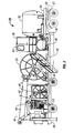
- FIG. 1 a tractor 10 having either a gasoline engine or a diesel engine is illustrated and which is used to pull the trailer 20 illustrated in FIG. 2 and which also uses its engine to drive all of the components which are illustrated in FIG. 1. and FIG. 2, on the tractor 10 , and the trailer 20 , respectively.
- the chassis 11 of the tractor 10 may be, for example, a Freightliner.
- the tractor 10 also has a hydraulic tank 12 and a tank holddown unit 13 which secures the hydraulic tank to the chassis.
- a hydraulic pump 14 has a coupling and a drive mechanism connected to its one end.
- the coupling 16 is connected into a transfer case and drive shaft mechanism 17 .
- a hydraulic pump 18 is one of many hydraulic pumps in the tractor assembly 10 and also includes various hydraulic pumps within the assembly 19 .
- the assembly 15 is a hydraulic pump which includes a clutch pulley being driven by the engine located within the tractor 10 .
- the tractor bed 21 has an assembly 22 which is used to connect the tractor to the trailer as illustrated in FIG. 2.
- a cryogenic nitrogen tank 32 mounted on the trailer bed 30 which is connected to the tractor bed 21 by way of the mechanism 22 .
- liquid nitrogen has a greatly reduced volume compared to the volume of gaseous nitrogen.
- Nitrogen when frozen to ⁇ 320° F., is a liquid and accordingly, it is much preferred to transport the liquid nitrogen to the well site to provide additional volume of nitrogen gas which is to be pumped into the well.
- a control cabin 34 mounted on the tractor bed 30 in which the electrical and hydraulic units 36 are controlled by a human operator.
- the nitrogen system 38 which is described in more detail hereinafter is also located on the tractor bed as is a heat exchanger 40 which is used to heat up the pumped liquid nitrogen to a temperature which causes the liquid to become gaseous, which can then be pumped into the well.
- the piping system 42 enables the gaseous nitrogen to be pumped into one end of the coiled tubing to allow the gaseous nitrogen to be pumped out of the other end of the coiled tubing.
- An injector unit 44 is situated on the tractor bed floor.
- a hydraulically driven crane 46 is also situated on the tractor bed floor for situating the coiled tubing injector 44 immediately above the well being treated.
- a hose reel 48 and a coiled tubing reel 50 are also situated on the tractor floor.
- a goose neck 52 is also situated on the tractor floor adjacent the coiled tubing injector system 44 for feeding the coiled tubing from the reel into the injector.
- a stripper 54 is located on the lower end of the coiled tubing injector system 44 for enabling the coiled tubing to be placed into the well being treated.
- a BOP unit 56 is also located on the tractor floor to be used in shutting in the well to be treated, if needed.
- FIG. 3 there is illustrated in block diagram some of the components which are illustrated in FIGS. 1 and 2.
- the liquid nitrogen tank 32 has its output connected into the input of a hydraulic pump 64 whose output is connected into the input of the heat exchanger 40 illustrated in FIG. 2.
- the tractor engine 70 which may be either gasoline powered or diesel powered has a hot water line 72 connected to its radiator and which provides hot water to the heat exchanger 40 .
- a return line 74 from the heat exchanger returns the water from the heat exchanger back into the radiator of the tractor engine 70 .
- the pump 64 is designed to pump the liquid nitrogen having a temperature near ⁇ 320° F. into the input of the heat exchanger 40 . Such pumps are commonly available in the industry for pumping liquid nitrogen.
- the heat exchanger 40 will cause the liquid nitrogen to rise above a gasification point which is near 0° F. so that the output from the heat exchanger is gaseous nitrogen.
- a gas line 76 can then return a portion of the gaseous nitrogen through the valve 78 back into the return line 80 which enables some of the gaseous nitrogen to be returned into the top of the nitrogen tank 32 , if and when desired.
- the output of the heat exchanger 40 is also coupled into one end of the coiled tubing illustrated in the box 82 through as many valves as are necessary for turning the nitrogen on or off to the coiled tubing 82 .
- One such control valve is illustrated as valve 84 .
- the valve 84 would preferably be a three-way valve which can either cut the gaseous nitrogen off so that it would not flow either into the coiled tubing or the valve 78 or would flow into only one or the other of the coiled tubing 82 and the valve 78 .
- a hydraulic pump 90 is connected into a hydraulic motor 92 which is used to drive the chains of the injector 44 which can either move the coiled tubing into the well being treated or pull the coiled tubing out of the well being treated, as desired, depending on the direction of the chain rotation.
- Another hydraulic pump 96 drives a motor 98 to drive the crane 46 illustrated in FIG. 2.
- Another hydraulic pump 100 drives a motor 102 which in turn drives any one or more miscellaneous items requiring a hydraulic activation as desired.
- the tractor engine 70 drives each of the hydraulic pumps 64 , 90 , 96 and 100 as shown by the line 106 .
- the hydraulic pump 64 , 90 , 96 and 100 are preferably driven by one or more belts which can be used with clutch pulleys as desired.
- a compressor unit 108 which is also driven by the tractor engine 70 is run off of the drive line 106 to assist in keeping the liquid nitrogen down to its desired temperature.
- tractor engine 70 is obviously and desirably located on the tractor, and the coiled tubing, the injector, and the crane, as well as the liquid nitrogen tank 32 are preferably located on the tractor, most of the other items identified in FIG. 3 can be found on either the tractor and/or the trailer as desired.
- the important feature of this invention is to recognize that all of the items shown in FIG. 3 are located on a combined tractor/trailer configuration which does not require the use of either another tractor or another trailer.
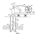
- FIG. 4 there is a simplified schematic illustrating the process contemplated by this invention for treating a producing oil or gas well which has, for whatever the reason, either quit producing or has started producing with a reduced volume of oil or gas.
- the tractor trailer illustrated in FIGS. 1 and 2 is delivered to the site of the well 110 which typically is cased with steel casing 112 and which has a string of production tubing 114 running down to the pay zone 116 in the surrounding formation and which has a pair of packers 118 and 120 which straddle the pay zone.
- the casing 112 has a plurality of perforations 122 which enable the oil or the gas to leave the pay zone and come into the interior of the well.
- the production tubing 114 has a screen or other holes in it 124 which allow the oil or gas to leave the pay zone 116 , come through the perforations 122 and enter the production tubing 114 which then allows the oil or gas to travel to the earth's surface.
- the packer 118 can remain in the cased borehole as illustrated, unbypassed, and the gaseous nitrogen when bubbled out of the end of the coiled tubing beneath the perforations, will drive sand and/or the water back to the earth's surface through the production tubing itself.
- the gaseous nitrogen be introduced from the earth's surface by passing the gaseous nitrogen through the coiled tubing from the coiled tubing reel located on the bed of the tractor.
- the coiled tubing injector 44 is moved by the crane unit 46 to be immediately above the Christmas Tree 130 which is, of course, the well-known oilfield apparatus which is placed at the top of the producing well 110 .
- the coiled tubing 130 is run through a well-known stripper into the interior of the Christmas Tree 130 and enters the interior of the production tubing string 114 without causing any leaks of any substance within the well to be vented into the atmosphere.
- the gaseous nitrogen is then caused to exit the lower end of the coiled tubing 130 , usually as the coiled tubing is being pushed into the production tubing, or can be turned on after the coiled tubing is in place in the well, if desired.
- the gaseous nitrogen then causes any water and/or sand which is plugging up the system to be routed through the annulus between the production tubing and the casing to cause the sand and/or the water to be removed from the system, which allows the well to again become productive. While the injector system 44 is shown in block diagram, such injector systems are well-known in the art as described and illustrated in U.S. Pat. No. 5,566,764, the disclosure of Which is incorporated herein by reference.
- Such systems normally involve the use of one or two rotating chains which can be caused to rotate in one direction to grab a hold of the coiled tubing and inject it into the tubing within the well, or by reversing the direction of the motor, the tubing can be pulled out of the well.
- the hydraulic pump 90 drives the motor 92 which causes the one or more chains to rotate within the injector 44 , for example, as illustrated with respect to the aforementioned U.S. Pat. No. 5,566,764.
- the present invention contemplates using the liquid nitrogen tank 32 illustrated on the trailer 20 to generate gaseous nitrogen
- the invention also contemplates that instead of using the tank 32 illustrated in FIG. 2 as a source of liquid nitrogen, there are additional sources which can be utilized.
- nitrogen generators can be used, shown in FIG. 5, which extract nitrogen from the atmosphere which can eliminate the costs of transporting and filling nitrogen tanks.
- Some of such nitrogen generators utilize a membrane, shown in FIG. 6, which allows nitrogen-rich air from the earth's atmosphere to be continuously fed into bundle housing. The air reaches the center of the bundle of membrane fibers which at that point, consists mostly of gaseous nitrogen. The nitrogen collects in the mandrel at the center of the bundle.
- the oxygen and other fast gases pass through the wall of the membrane fibers as they go through the fibers to be collected at the end. Oxygen and the other fast gases are continuously collected and are moved from the bundle, thus leaving the nitrogen available to be used for injection into the well being treated.
- the gaseous nitrogen source can be one or more tanks of compressed nitrogen gas such as the tanks 200 , 202 , 204 and 206 illustrated in FIG. 7.
Landscapes
- Engineering & Computer Science (AREA)
- Life Sciences & Earth Sciences (AREA)
- Geology (AREA)
- Mining & Mineral Resources (AREA)
- Physics & Mathematics (AREA)
- Environmental & Geological Engineering (AREA)
- Fluid Mechanics (AREA)
- General Life Sciences & Earth Sciences (AREA)
- Geochemistry & Mineralogy (AREA)
- Mechanical Engineering (AREA)
- Pipeline Systems (AREA)
- Separation Using Semi-Permeable Membranes (AREA)
Abstract
Description
- This invention relates, generally, to the treatment of oil and gas wells using nitrogen to increase the production capability of the wells, and specifically, to providing on a single tractor/trailer combination, all of the equipment accessories to pump nitrogen through a coiled tubing into the wells being treated.
- It is known in the art to provide work over operations using gaseous nitrogen to remove sand and/or water or other impediments to production. The prior art has not recognized that a single tractor trailer unit can be provided with all of the equipment and accessories for running a nitrogen service in combination with a coiled tubing unit to treat such wells. The prior art typically brings two tractor trailer assemblies to the well to be treated, one having a coiled tubing unit, and one having the nitrogen unit. Because of the duplicity of the tractor trailer units, this has caused a doubling of the transportation costs, a doubling of the personnel required to have the units arrive at the well, and a doubling of the number of personnel required to run this service.
- It is of the primary object of this present invention to provide a combined tractor trailer unit which utilizes a single tractor and a single trailer to provide a service for treating wells with a combined tractor trailer unit through which gaseous nitrogen can be pumped.
- FIG. 1 is an elevated, schematic view of a tractor unit which can be used in accordance with the present invention;
- FIG. 2 is an elevated, pictorial view of a trailer unit which can be used in accordance with the present invention with the tractor illustrated in FIG. 1.;
- FIG. 3 illustrates, in block diagram, the various systems which are used in accordance with the present invention to treat a well with nitrogen;
- FIG. 4 is an elevated, diagrammatic view of an oil or gas well which is being treated with nitrogen from the coiled tubing unit in accordance with the present invention;
- FIG. 5 is a pictorial view of three nitrogen generators which can be used as a substitute for the liquid nitrogen tank;
- FIG. 6 is a pictorial view of a unit using membrane technology to pull gaseous nitrogen out of the atmosphere; and
- FIG. 7 is an elevated pictorial view of a plurality of tanks used for storing compressed nitrogen gas.
- Referring now to FIG. 1, a
tractor 10 having either a gasoline engine or a diesel engine is illustrated and which is used to pull thetrailer 20 illustrated in FIG. 2 and which also uses its engine to drive all of the components which are illustrated in FIG. 1. and FIG. 2, on thetractor 10, and thetrailer 20, respectively. Thechassis 11 of thetractor 10 may be, for example, a Freightliner. Thetractor 10 also has ahydraulic tank 12 and atank holddown unit 13 which secures the hydraulic tank to the chassis. Ahydraulic pump 14 has a coupling and a drive mechanism connected to its one end. Thecoupling 16 is connected into a transfer case anddrive shaft mechanism 17. Ahydraulic pump 18 is one of many hydraulic pumps in thetractor assembly 10 and also includes various hydraulic pumps within theassembly 19. It should be appreciated that all of the mechanisms illustrated with thetractor 20 in FIG. 2 are driven by hydraulic pumps located on thetractor chassis 10. Theassembly 15 is a hydraulic pump which includes a clutch pulley being driven by the engine located within thetractor 10. Thetractor bed 21 has anassembly 22 which is used to connect the tractor to the trailer as illustrated in FIG. 2. - Referring now to FIG. 2 in more detail, mounted on the
trailer bed 30 which is connected to thetractor bed 21 by way of themechanism 22, is acryogenic nitrogen tank 32. As is well known in this art, liquid nitrogen has a greatly reduced volume compared to the volume of gaseous nitrogen. Nitrogen, when frozen to −320° F., is a liquid and accordingly, it is much preferred to transport the liquid nitrogen to the well site to provide additional volume of nitrogen gas which is to be pumped into the well. Also mounted on thetractor bed 30 is acontrol cabin 34 in which the electrical andhydraulic units 36 are controlled by a human operator. Thenitrogen system 38 which is described in more detail hereinafter is also located on the tractor bed as is aheat exchanger 40 which is used to heat up the pumped liquid nitrogen to a temperature which causes the liquid to become gaseous, which can then be pumped into the well. Thepiping system 42 enables the gaseous nitrogen to be pumped into one end of the coiled tubing to allow the gaseous nitrogen to be pumped out of the other end of the coiled tubing. - An
injector unit 44, also described in more detail hereinafter, is situated on the tractor bed floor. A hydraulically drivencrane 46 is also situated on the tractor bed floor for situating the coiledtubing injector 44 immediately above the well being treated. A hose reel 48 and a coiledtubing reel 50 are also situated on the tractor floor. A goose neck 52 is also situated on the tractor floor adjacent the coiledtubing injector system 44 for feeding the coiled tubing from the reel into the injector. Astripper 54 is located on the lower end of the coiledtubing injector system 44 for enabling the coiled tubing to be placed into the well being treated. ABOP unit 56 is also located on the tractor floor to be used in shutting in the well to be treated, if needed. - Referring now to FIG. 3, there is illustrated in block diagram some of the components which are illustrated in FIGS. 1 and 2. The
liquid nitrogen tank 32 has its output connected into the input of ahydraulic pump 64 whose output is connected into the input of theheat exchanger 40 illustrated in FIG. 2. Thetractor engine 70, which may be either gasoline powered or diesel powered has ahot water line 72 connected to its radiator and which provides hot water to theheat exchanger 40. Areturn line 74 from the heat exchanger returns the water from the heat exchanger back into the radiator of thetractor engine 70. Thepump 64 is designed to pump the liquid nitrogen having a temperature near −320° F. into the input of theheat exchanger 40. Such pumps are commonly available in the industry for pumping liquid nitrogen. As the liquid nitrogen is pumped through theheat exchanger 40, the heat exchanger will cause the liquid nitrogen to rise above a gasification point which is near 0° F. so that the output from the heat exchanger is gaseous nitrogen. Agas line 76 can then return a portion of the gaseous nitrogen through the valve 78 back into thereturn line 80 which enables some of the gaseous nitrogen to be returned into the top of thenitrogen tank 32, if and when desired. The output of theheat exchanger 40 is also coupled into one end of the coiled tubing illustrated in thebox 82 through as many valves as are necessary for turning the nitrogen on or off to thecoiled tubing 82. One such control valve is illustrated as valve 84. The valve 84 would preferably be a three-way valve which can either cut the gaseous nitrogen off so that it would not flow either into the coiled tubing or the valve 78 or would flow into only one or the other of thecoiled tubing 82 and the valve 78. - A
hydraulic pump 90 is connected into ahydraulic motor 92 which is used to drive the chains of theinjector 44 which can either move the coiled tubing into the well being treated or pull the coiled tubing out of the well being treated, as desired, depending on the direction of the chain rotation. - Another
hydraulic pump 96 drives amotor 98 to drive thecrane 46 illustrated in FIG. 2. - Another
hydraulic pump 100 drives amotor 102 which in turn drives any one or more miscellaneous items requiring a hydraulic activation as desired. - It should be appreciated that the
tractor engine 70 drives each of thehydraulic pumps line 106. Coming off of thetractor engine 70, thehydraulic pump compressor unit 108 which is also driven by thetractor engine 70 is run off of thedrive line 106 to assist in keeping the liquid nitrogen down to its desired temperature. - It should be appreciated that while the
tractor engine 70 is obviously and desirably located on the tractor, and the coiled tubing, the injector, and the crane, as well as theliquid nitrogen tank 32 are preferably located on the tractor, most of the other items identified in FIG. 3 can be found on either the tractor and/or the trailer as desired. The important feature of this invention is to recognize that all of the items shown in FIG. 3 are located on a combined tractor/trailer configuration which does not require the use of either another tractor or another trailer. - Referring now to FIG. 4, there is a simplified schematic illustrating the process contemplated by this invention for treating a producing oil or gas well which has, for whatever the reason, either quit producing or has started producing with a reduced volume of oil or gas. The tractor trailer illustrated in FIGS. 1 and 2 is delivered to the site of the
well 110 which typically is cased withsteel casing 112 and which has a string ofproduction tubing 114 running down to thepay zone 116 in the surrounding formation and which has a pair ofpackers casing 112 has a plurality ofperforations 122 which enable the oil or the gas to leave the pay zone and come into the interior of the well. Theproduction tubing 114 has a screen or other holes in it 124 which allow the oil or gas to leave thepay zone 116, come through theperforations 122 and enter theproduction tubing 114 which then allows the oil or gas to travel to the earth's surface. - There are various things which can cause the well in question to quit producing at a rate which it has been experiencing before. There can be sand which enters through the perforations and the holes in the production tubing which plug it up substantially and reduce the amount of oil or gas being produced. Another problem which exists in addition to the sanding problem is the existence of water which may be sitting on top of the oil or gas being produced. Since many of the pay zones contain water, and because of the weight of the water sitting on top of the oil or gas being produced, the oil or gas simply will not proceed up to the surface. To overcome either one of these problems, it is desirable to pump gaseous nitrogen down through the
production tubing 114 to push the sand and/or the water out of theproduction tubing string 114 and back up through the annulus between the steel casing and the production tubing. This can be accomplished either by not using theproduction packer 118 or by having bypass valves which pass through theproduction packer 118 and allow the sand and/or the water to be produced up the annulus through the earth's surface and once again, place the production of the pay zone back to what it was before the problem occurred. In an alternative mode, thepacker 118 can remain in the cased borehole as illustrated, unbypassed, and the gaseous nitrogen when bubbled out of the end of the coiled tubing beneath the perforations, will drive sand and/or the water back to the earth's surface through the production tubing itself. - To accomplish all of this, it is desirable that the gaseous nitrogen be introduced from the earth's surface by passing the gaseous nitrogen through the coiled tubing from the coiled tubing reel located on the bed of the tractor. To get the coiled
tubing 130 into the interior of theproduction tubing string 114, the coiledtubing injector 44 is moved by thecrane unit 46 to be immediately above theChristmas Tree 130 which is, of course, the well-known oilfield apparatus which is placed at the top of the producing well 110. Thecoiled tubing 130 is run through a well-known stripper into the interior of theChristmas Tree 130 and enters the interior of theproduction tubing string 114 without causing any leaks of any substance within the well to be vented into the atmosphere. The gaseous nitrogen is then caused to exit the lower end of the coiledtubing 130, usually as the coiled tubing is being pushed into the production tubing, or can be turned on after the coiled tubing is in place in the well, if desired. The gaseous nitrogen then causes any water and/or sand which is plugging up the system to be routed through the annulus between the production tubing and the casing to cause the sand and/or the water to be removed from the system, which allows the well to again become productive. While theinjector system 44 is shown in block diagram, such injector systems are well-known in the art as described and illustrated in U.S. Pat. No. 5,566,764, the disclosure of Which is incorporated herein by reference. Such systems normally involve the use of one or two rotating chains which can be caused to rotate in one direction to grab a hold of the coiled tubing and inject it into the tubing within the well, or by reversing the direction of the motor, the tubing can be pulled out of the well. As illustrated in FIG. 3, thehydraulic pump 90 drives themotor 92 which causes the one or more chains to rotate within theinjector 44, for example, as illustrated with respect to the aforementioned U.S. Pat. No. 5,566,764. - It should be appreciated that although the present invention contemplates using the
liquid nitrogen tank 32 illustrated on thetrailer 20 to generate gaseous nitrogen, the invention also contemplates that instead of using thetank 32 illustrated in FIG. 2 as a source of liquid nitrogen, there are additional sources which can be utilized. For example, nitrogen generators can be used, shown in FIG. 5, which extract nitrogen from the atmosphere which can eliminate the costs of transporting and filling nitrogen tanks. Some of such nitrogen generators utilize a membrane, shown in FIG. 6, which allows nitrogen-rich air from the earth's atmosphere to be continuously fed into bundle housing. The air reaches the center of the bundle of membrane fibers which at that point, consists mostly of gaseous nitrogen. The nitrogen collects in the mandrel at the center of the bundle. As the air passes through the bundle of membrane fibers, the oxygen and other fast gases pass through the wall of the membrane fibers as they go through the fibers to be collected at the end. Oxygen and the other fast gases are continuously collected and are moved from the bundle, thus leaving the nitrogen available to be used for injection into the well being treated. By stacking a plurality of such nitrogen generators, available volumes are provided which have an increased flow capability. - In an alternative mode, albeit not as preferred as either the liquid nitrogen or the nitrogen generator modes, the gaseous nitrogen source can be one or more tanks of compressed nitrogen gas such as the
tanks
Claims (11)
Priority Applications (11)
| Application Number | Priority Date | Filing Date | Title |
|---|---|---|---|
| US10/127,092 US6702011B2 (en) | 2002-04-22 | 2002-04-22 | Combined nitrogen treatment system and coiled tubing system in one tractor/trailer apparatus |
| US10/170,281 US20030196797A1 (en) | 2002-04-22 | 2002-06-12 | Coiled tubing having multiple strings of smaller tubing embedded therein |
| US10/339,038 US20030196813A1 (en) | 2002-04-22 | 2003-01-09 | Method of treating and measuring various parameters in pipelines |
| US10/339,588 US20030196812A1 (en) | 2002-04-22 | 2003-01-09 | Coiled tubing for insertion into coiled tubing |
| US10/339,042 US20030196815A1 (en) | 2002-04-22 | 2003-01-09 | Method for operating a submersible pump |
| US10/339,130 US20030196811A1 (en) | 2002-04-22 | 2003-01-09 | Method of treating and measuring various parameters in formations |
| PCT/US2003/012197 WO2003089753A2 (en) | 2002-04-22 | 2003-04-21 | Coiled tubing having multiple strings of smaller tubing embedded therein |
| CA002483796A CA2483796C (en) | 2002-04-22 | 2003-04-21 | Coiled tubing having multiple strings of smaller tubing embedded therein |
| MXPA04010356A MXPA04010356A (en) | 2002-04-22 | 2003-04-21 | Coiled tubing having multiple strings of smaller tubing embedded therein. |
| AU2003231737A AU2003231737A1 (en) | 2002-04-22 | 2003-04-21 | Coiled tubing having multiple strings of smaller tubing embedded therein |
| US10/691,309 US7051818B2 (en) | 2002-04-22 | 2003-10-22 | Three in one combined power unit for nitrogen system, fluid system, and coiled tubing system |
Applications Claiming Priority (1)
| Application Number | Priority Date | Filing Date | Title |
|---|---|---|---|
| US10/127,092 US6702011B2 (en) | 2002-04-22 | 2002-04-22 | Combined nitrogen treatment system and coiled tubing system in one tractor/trailer apparatus |
Related Child Applications (2)
| Application Number | Title | Priority Date | Filing Date |
|---|---|---|---|
| US10/170,281 Continuation-In-Part US20030196797A1 (en) | 2002-04-22 | 2002-06-12 | Coiled tubing having multiple strings of smaller tubing embedded therein |
| US10/691,309 Continuation-In-Part US7051818B2 (en) | 2002-04-22 | 2003-10-22 | Three in one combined power unit for nitrogen system, fluid system, and coiled tubing system |
Publications (2)
| Publication Number | Publication Date |
|---|---|
| US20030196793A1 true US20030196793A1 (en) | 2003-10-23 |
| US6702011B2 US6702011B2 (en) | 2004-03-09 |
Family
ID=29215175
Family Applications (1)
| Application Number | Title | Priority Date | Filing Date |
|---|---|---|---|
| US10/127,092 Expired - Fee Related US6702011B2 (en) | 2002-04-22 | 2002-04-22 | Combined nitrogen treatment system and coiled tubing system in one tractor/trailer apparatus |
Country Status (1)
| Country | Link |
|---|---|
| US (1) | US6702011B2 (en) |
Cited By (12)
| Publication number | Priority date | Publication date | Assignee | Title |
|---|---|---|---|---|
| US6877555B2 (en) | 2001-04-24 | 2005-04-12 | Shell Oil Company | In situ thermal processing of an oil shale formation while inhibiting coking |
| US6932155B2 (en) | 2001-10-24 | 2005-08-23 | Shell Oil Company | In situ thermal processing of a hydrocarbon containing formation via backproducing through a heater well |
| US7011154B2 (en) | 2000-04-24 | 2006-03-14 | Shell Oil Company | In situ recovery from a kerogen and liquid hydrocarbon containing formation |
| US7066254B2 (en) | 2001-04-24 | 2006-06-27 | Shell Oil Company | In situ thermal processing of a tar sands formation |
| US7073578B2 (en) | 2002-10-24 | 2006-07-11 | Shell Oil Company | Staged and/or patterned heating during in situ thermal processing of a hydrocarbon containing formation |
| US7077199B2 (en) | 2001-10-24 | 2006-07-18 | Shell Oil Company | In situ thermal processing of an oil reservoir formation |
| US7090013B2 (en) | 2001-10-24 | 2006-08-15 | Shell Oil Company | In situ thermal processing of a hydrocarbon containing formation to produce heated fluids |
| US7104319B2 (en) | 2001-10-24 | 2006-09-12 | Shell Oil Company | In situ thermal processing of a heavy oil diatomite formation |
| US7121342B2 (en) | 2003-04-24 | 2006-10-17 | Shell Oil Company | Thermal processes for subsurface formations |
| US7165615B2 (en) | 2001-10-24 | 2007-01-23 | Shell Oil Company | In situ recovery from a hydrocarbon containing formation using conductor-in-conduit heat sources with an electrically conductive material in the overburden |
| CN108278107A (en) * | 2017-12-26 | 2018-07-13 | 中国石油天然气集团公司 | The control system and drilling machine of drilling machine |
| US20220186581A1 (en) * | 2020-12-11 | 2022-06-16 | Heartland Revitalization Services Inc. | Portable foam injection system |
Families Citing this family (11)
| Publication number | Priority date | Publication date | Assignee | Title |
|---|---|---|---|---|
| US7051818B2 (en) * | 2002-04-22 | 2006-05-30 | P.E.T. International, Inc. | Three in one combined power unit for nitrogen system, fluid system, and coiled tubing system |
| CA2421376A1 (en) * | 2003-03-07 | 2004-09-07 | Robert Joseph Foster | Hybrid coiled tubing/fluid pumping unit |
| EP1963621A1 (en) * | 2005-07-16 | 2008-09-03 | P.E.T. International, Inc. | Combined nitrogen generation system and well servicing fluid system in one power unit apparatus |
| CA2529921C (en) * | 2005-12-13 | 2012-06-05 | Foremost Industries Inc. | Coiled tubing injector system |
| CA2646310A1 (en) * | 2006-03-20 | 2007-09-27 | Wise Well Intervention Services, Inc. | Well servicing combination unit |
| US20100038100A1 (en) * | 2006-09-18 | 2010-02-18 | Lorne Schuetzle | Fluid supply unit |
| US8506267B2 (en) | 2007-09-10 | 2013-08-13 | Schlumberger Technology Corporation | Pump assembly |
| US7703528B2 (en) * | 2008-01-15 | 2010-04-27 | Halliburton Energy Services, Inc. | Reducing CO2 emissions from oilfield diesel engines |
| US8590612B2 (en) * | 2009-04-21 | 2013-11-26 | Schlumberger Technology Corporation | System and method to provide well service unit with integrated gas delivery |
| CA2801571A1 (en) | 2010-06-04 | 2011-12-08 | Dow Global Technologies Llc | Injection system for enhanced oil recovery |
| US9458707B2 (en) | 2012-12-03 | 2016-10-04 | Dow Global Technologies Llc | Injection system for enhanced oil recovery |
Family Cites Families (4)
| Publication number | Priority date | Publication date | Assignee | Title |
|---|---|---|---|---|
| US4585061A (en) * | 1983-10-18 | 1986-04-29 | Hydra-Rig Incorporated | Apparatus for inserting and withdrawing coiled tubing with respect to a well |
| US6273188B1 (en) * | 1998-12-11 | 2001-08-14 | Schlumberger Technology Corporation | Trailer mounted coiled tubing rig |
| US6264128B1 (en) * | 1998-12-14 | 2001-07-24 | Schlumberger Technology Corporation | Levelwind system for coiled tubing reel |
| US6230805B1 (en) * | 1999-01-29 | 2001-05-15 | Schlumberger Technology Corporation | Methods of hydraulic fracturing |
-
2002
- 2002-04-22 US US10/127,092 patent/US6702011B2/en not_active Expired - Fee Related
Cited By (28)
| Publication number | Priority date | Publication date | Assignee | Title |
|---|---|---|---|---|
| US7011154B2 (en) | 2000-04-24 | 2006-03-14 | Shell Oil Company | In situ recovery from a kerogen and liquid hydrocarbon containing formation |
| US6880633B2 (en) | 2001-04-24 | 2005-04-19 | Shell Oil Company | In situ thermal processing of an oil shale formation to produce a desired product |
| US6877555B2 (en) | 2001-04-24 | 2005-04-12 | Shell Oil Company | In situ thermal processing of an oil shale formation while inhibiting coking |
| US7066254B2 (en) | 2001-04-24 | 2006-06-27 | Shell Oil Company | In situ thermal processing of a tar sands formation |
| US7100994B2 (en) | 2001-10-24 | 2006-09-05 | Shell Oil Company | Producing hydrocarbons and non-hydrocarbon containing materials when treating a hydrocarbon containing formation |
| US7104319B2 (en) | 2001-10-24 | 2006-09-12 | Shell Oil Company | In situ thermal processing of a heavy oil diatomite formation |
| US7063145B2 (en) | 2001-10-24 | 2006-06-20 | Shell Oil Company | Methods and systems for heating a hydrocarbon containing formation in situ with an opening contacting the earth's surface at two locations |
| US6991045B2 (en) | 2001-10-24 | 2006-01-31 | Shell Oil Company | Forming openings in a hydrocarbon containing formation using magnetic tracking |
| US7066257B2 (en) | 2001-10-24 | 2006-06-27 | Shell Oil Company | In situ recovery from lean and rich zones in a hydrocarbon containing formation |
| US7165615B2 (en) | 2001-10-24 | 2007-01-23 | Shell Oil Company | In situ recovery from a hydrocarbon containing formation using conductor-in-conduit heat sources with an electrically conductive material in the overburden |
| US7077199B2 (en) | 2001-10-24 | 2006-07-18 | Shell Oil Company | In situ thermal processing of an oil reservoir formation |
| US7077198B2 (en) | 2001-10-24 | 2006-07-18 | Shell Oil Company | In situ recovery from a hydrocarbon containing formation using barriers |
| US7086465B2 (en) | 2001-10-24 | 2006-08-08 | Shell Oil Company | In situ production of a blending agent from a hydrocarbon containing formation |
| US7090013B2 (en) | 2001-10-24 | 2006-08-15 | Shell Oil Company | In situ thermal processing of a hydrocarbon containing formation to produce heated fluids |
| US6932155B2 (en) | 2001-10-24 | 2005-08-23 | Shell Oil Company | In situ thermal processing of a hydrocarbon containing formation via backproducing through a heater well |
| US7051808B1 (en) | 2001-10-24 | 2006-05-30 | Shell Oil Company | Seismic monitoring of in situ conversion in a hydrocarbon containing formation |
| US7114566B2 (en) | 2001-10-24 | 2006-10-03 | Shell Oil Company | In situ thermal processing of a hydrocarbon containing formation using a natural distributed combustor |
| US7156176B2 (en) | 2001-10-24 | 2007-01-02 | Shell Oil Company | Installation and use of removable heaters in a hydrocarbon containing formation |
| US7128153B2 (en) | 2001-10-24 | 2006-10-31 | Shell Oil Company | Treatment of a hydrocarbon containing formation after heating |
| US7121341B2 (en) | 2002-10-24 | 2006-10-17 | Shell Oil Company | Conductor-in-conduit temperature limited heaters |
| US7073578B2 (en) | 2002-10-24 | 2006-07-11 | Shell Oil Company | Staged and/or patterned heating during in situ thermal processing of a hydrocarbon containing formation |
| US7219734B2 (en) | 2002-10-24 | 2007-05-22 | Shell Oil Company | Inhibiting wellbore deformation during in situ thermal processing of a hydrocarbon containing formation |
| US7121342B2 (en) | 2003-04-24 | 2006-10-17 | Shell Oil Company | Thermal processes for subsurface formations |
| US7360588B2 (en) | 2003-04-24 | 2008-04-22 | Shell Oil Company | Thermal processes for subsurface formations |
| US8579031B2 (en) | 2003-04-24 | 2013-11-12 | Shell Oil Company | Thermal processes for subsurface formations |
| CN108278107A (en) * | 2017-12-26 | 2018-07-13 | 中国石油天然气集团公司 | The control system and drilling machine of drilling machine |
| US20220186581A1 (en) * | 2020-12-11 | 2022-06-16 | Heartland Revitalization Services Inc. | Portable foam injection system |
| US11846154B2 (en) * | 2020-12-11 | 2023-12-19 | Heartland Revitalization Services Inc. | Portable foam injection system |
Also Published As
| Publication number | Publication date |
|---|---|
| US6702011B2 (en) | 2004-03-09 |
Similar Documents
| Publication | Publication Date | Title |
|---|---|---|
| US6702011B2 (en) | Combined nitrogen treatment system and coiled tubing system in one tractor/trailer apparatus | |
| US7051818B2 (en) | Three in one combined power unit for nitrogen system, fluid system, and coiled tubing system | |
| CA2483796C (en) | Coiled tubing having multiple strings of smaller tubing embedded therein | |
| US20090050311A1 (en) | Well servicing combination unit | |
| US7207389B2 (en) | Hybrid coiled tubing/fluid pumping unit | |
| EP2904200B1 (en) | Mobile, modular, electrically powered system for use in fracturing underground formations using liquid petroleum gas | |
| US12270287B2 (en) | Remotely-controlled pressure bleed-off system | |
| CN106574495A (en) | Hydraulic fracturing system | |
| US4718486A (en) | Portable jet pump system with pump lowered down hole and raised with coiled pipe and return line | |
| US10612678B1 (en) | Method of servicing an electronically controlled PRV system | |
| US4125162A (en) | Well flow system and method | |
| US20090151927A1 (en) | Combined nitrogen generation system and well servicing fluid system in one power unit apparatus | |
| US20170107793A1 (en) | Method and system for purging coil tubing using onsite gas | |
| US3477513A (en) | Well cleaning with mixed liquefied propane and butane solvent | |
| US6662885B2 (en) | Method and apparatus for providing a stream of pressurized substantially inert gas | |
| CA2457307C (en) | Hybrid coiled tubing/fluid pumping unit |
Legal Events
| Date | Code | Title | Description |
|---|---|---|---|
| CC | Certificate of correction | ||
| AS | Assignment |
Owner name: P.E.T. INTERNATIONAL, INC., TEXAS Free format text: ASSIGNMENT OF ASSIGNORS INTEREST;ASSIGNORS:CRAWFORD, JAMES B;LAMB, EDWARD;REEL/FRAME:017507/0990 Effective date: 20060420 |
|
| AS | Assignment |
Owner name: GENERAL ELECTRIC CAPITAL CORPORATION, CONNECTICUT Free format text: SECURITY AGREEMENT;ASSIGNOR:P.E.T. INTERNATIONAL, INC.;REEL/FRAME:017564/0576 Effective date: 20060502 |
|
| FPAY | Fee payment |
Year of fee payment: 4 |
|
| AS | Assignment |
Owner name: WISE WELL INTERVENTION SERVICES, INC., TEXAS Free format text: FULL RELEASE OF PATENT SECURITY AGREEMENT;ASSIGNOR:GENERAL ELECTRIC CAPITAL CORPORATION, AS AGENT;REEL/FRAME:019805/0949 Effective date: 20070831 |
|
| AS | Assignment |
Owner name: TCW ASSET MANAGEMENT COMPANY, TEXAS Free format text: SECURITY AGREEMENT;ASSIGNOR:WISE WELL INTERVENTION SERVICES, INC.;REEL/FRAME:019817/0807 Effective date: 20070831 |
|
| AS | Assignment |
Owner name: WS (BLOCKER), INC., CALIFORNIA Free format text: BILL OF SALE/ASSIGNMENT;ASSIGNOR:WISE WELL INTERVENTION SERVICES, INC.;REEL/FRAME:023586/0279 Effective date: 20070831 |
|
| REMI | Maintenance fee reminder mailed | ||
| FPAY | Fee payment |
Year of fee payment: 8 |
|
| SULP | Surcharge for late payment |
Year of fee payment: 7 |
|
| REMI | Maintenance fee reminder mailed | ||
| LAPS | Lapse for failure to pay maintenance fees | ||
| STCH | Information on status: patent discontinuation |
Free format text: PATENT EXPIRED DUE TO NONPAYMENT OF MAINTENANCE FEES UNDER 37 CFR 1.362 |
|
| STCH | Information on status: patent discontinuation |
Free format text: PATENT EXPIRED DUE TO NONPAYMENT OF MAINTENANCE FEES UNDER 37 CFR 1.362 |
|
| FP | Lapsed due to failure to pay maintenance fee |
Effective date: 20160309 |