US20030196691A1 - Repaired solar panel and method of preparing same - Google Patents
Repaired solar panel and method of preparing same Download PDFInfo
- Publication number
- US20030196691A1 US20030196691A1 US10/326,273 US32627302A US2003196691A1 US 20030196691 A1 US20030196691 A1 US 20030196691A1 US 32627302 A US32627302 A US 32627302A US 2003196691 A1 US2003196691 A1 US 2003196691A1
- Authority
- US
- United States
- Prior art keywords
- solar cell
- connectors
- solar
- replacement
- defective
- Prior art date
- Legal status (The legal status is an assumption and is not a legal conclusion. Google has not performed a legal analysis and makes no representation as to the accuracy of the status listed.)
- Granted
Links
Images

Classifications
-
- H—ELECTRICITY
- H10—SEMICONDUCTOR DEVICES; ELECTRIC SOLID-STATE DEVICES NOT OTHERWISE PROVIDED FOR
- H10F—INORGANIC SEMICONDUCTOR DEVICES SENSITIVE TO INFRARED RADIATION, LIGHT, ELECTROMAGNETIC RADIATION OF SHORTER WAVELENGTH OR CORPUSCULAR RADIATION
- H10F19/00—Integrated devices, or assemblies of multiple devices, comprising at least one photovoltaic cell covered by group H10F10/00, e.g. photovoltaic modules
-
- B—PERFORMING OPERATIONS; TRANSPORTING
- B64—AIRCRAFT; AVIATION; COSMONAUTICS
- B64G—COSMONAUTICS; VEHICLES OR EQUIPMENT THEREFOR
- B64G1/00—Cosmonautic vehicles
- B64G1/22—Parts of, or equipment specially adapted for fitting in or to, cosmonautic vehicles
- B64G1/42—Arrangements or adaptations of power supply systems
- B64G1/44—Arrangements or adaptations of power supply systems using radiation, e.g. deployable solar arrays
- B64G1/443—Photovoltaic cell arrays
-
- H—ELECTRICITY
- H10—SEMICONDUCTOR DEVICES; ELECTRIC SOLID-STATE DEVICES NOT OTHERWISE PROVIDED FOR
- H10F—INORGANIC SEMICONDUCTOR DEVICES SENSITIVE TO INFRARED RADIATION, LIGHT, ELECTROMAGNETIC RADIATION OF SHORTER WAVELENGTH OR CORPUSCULAR RADIATION
- H10F19/00—Integrated devices, or assemblies of multiple devices, comprising at least one photovoltaic cell covered by group H10F10/00, e.g. photovoltaic modules
- H10F19/90—Structures for connecting between photovoltaic cells, e.g. interconnections or insulating spacers
- H10F19/902—Structures for connecting between photovoltaic cells, e.g. interconnections or insulating spacers for series or parallel connection of photovoltaic cells
- H10F19/904—Structures for connecting between photovoltaic cells, e.g. interconnections or insulating spacers for series or parallel connection of photovoltaic cells characterised by the shapes of the structures
-
- Y—GENERAL TAGGING OF NEW TECHNOLOGICAL DEVELOPMENTS; GENERAL TAGGING OF CROSS-SECTIONAL TECHNOLOGIES SPANNING OVER SEVERAL SECTIONS OF THE IPC; TECHNICAL SUBJECTS COVERED BY FORMER USPC CROSS-REFERENCE ART COLLECTIONS [XRACs] AND DIGESTS
- Y02—TECHNOLOGIES OR APPLICATIONS FOR MITIGATION OR ADAPTATION AGAINST CLIMATE CHANGE
- Y02E—REDUCTION OF GREENHOUSE GAS [GHG] EMISSIONS, RELATED TO ENERGY GENERATION, TRANSMISSION OR DISTRIBUTION
- Y02E10/00—Energy generation through renewable energy sources
- Y02E10/50—Photovoltaic [PV] energy
-
- Y—GENERAL TAGGING OF NEW TECHNOLOGICAL DEVELOPMENTS; GENERAL TAGGING OF CROSS-SECTIONAL TECHNOLOGIES SPANNING OVER SEVERAL SECTIONS OF THE IPC; TECHNICAL SUBJECTS COVERED BY FORMER USPC CROSS-REFERENCE ART COLLECTIONS [XRACs] AND DIGESTS
- Y10—TECHNICAL SUBJECTS COVERED BY FORMER USPC
- Y10S—TECHNICAL SUBJECTS COVERED BY FORMER USPC CROSS-REFERENCE ART COLLECTIONS [XRACs] AND DIGESTS
- Y10S136/00—Batteries: thermoelectric and photoelectric
- Y10S136/29—Testing, calibrating, treating, e.g. aging
-
- Y—GENERAL TAGGING OF NEW TECHNOLOGICAL DEVELOPMENTS; GENERAL TAGGING OF CROSS-SECTIONAL TECHNOLOGIES SPANNING OVER SEVERAL SECTIONS OF THE IPC; TECHNICAL SUBJECTS COVERED BY FORMER USPC CROSS-REFERENCE ART COLLECTIONS [XRACs] AND DIGESTS
- Y10—TECHNICAL SUBJECTS COVERED BY FORMER USPC
- Y10T—TECHNICAL SUBJECTS COVERED BY FORMER US CLASSIFICATION
- Y10T29/00—Metal working
- Y10T29/49—Method of mechanical manufacture
- Y10T29/49002—Electrical device making
- Y10T29/49117—Conductor or circuit manufacturing
- Y10T29/49169—Assembling electrical component directly to terminal or elongated conductor
Definitions
- the invention relates to a method for repairing solar a cell panel.
- German Patent Document DE 1 927 387 German Patent Document DE 2 113 410 describes a repair-friendly arrangement of solar cells, in which a defective cell can easily be removed from a module or string of solar cells.
- German Patent Document DE 195 39 699 C2 describes the utilization of defective solar modules of a laminated construction, in which the solar cells are delaminated and the solar cell module is disassembled into its components. This state of the art in each case requires a relatively high-expenditure intrusion into the solar cell panel or into the solar cells, such that the resulting repaired solar cell panels may suffer damage.
- the known repair methods according to the state of the art may, for example, require the following steps: The cover glass over the one or more solar cells is removed at the welding islands of the top “n-connectors” of the solar cells to permit them to be separated and carefully bent up, exposing connection webs directly behind the welds. Subsequently, the defective one or more solar cells is or are removed from the solar cell panel, the “p-connector” being retained on the panel. Then, one or more solar cells having a special repair connector are inserted into the repair site and the projecting n- and p-connectors are welded to the adjacent solar cells.
- solar cells includes a solar cell “assembly” (SCAs) consisting of the solar cell, the solar cell connector and cover glass.
- one or more replacement solar cells also in the form of solar cell assemblies (SCAs)—are glued onto the defective solar cell or cells and are electrically integrated in the panel by means of the existing cut-open connectors. Therefore, either one defective solar cell may exist in the panel onto which the one or more intact replacement solar cells are glued, or several defective solar cells may be present which are directly adjoining, grouped or spatially separated (particularly in the form of entire solar cell strings or solar cell modules), onto which one or more intact replacement solar cells are glued. In cases in which complete defective solar cell strings, solar cell modules or other defined groups of solar cells are present, complete replacement solar cell strings or replacement solar cell modules can correspondingly be glued thereon.
- SCAs solar cell assemblies
- the invention achieves a saving of components and materials. Another important advantage is a reduction of the repair time that is required for producing such repaired solar cell panels, because the time consuming separation of the defective solar cells is eliminated, only the connectors needing to be exposed.
- a further embodiment of the invention provides that the one or more replacement solar cells are provided with standard-type n-connectors and p-connectors which are electrically connected (particularly welded) to cut-open connectors of one or more adjacent intact solar cells.
- the replacement solar cells may be glued on by means of a silicone glue.
- the present invention can be used in the case of solar cell panels that are constructed for aerospace applications (for example, solar cell panels for satellites or other spacecraft).
- solar cell panels that are constructed for aerospace applications (for example, solar cell panels for satellites or other spacecraft).
- the use of repaired solar cell panels will be more cost-effective than, for example, a complete elimination of solar cell panels because of some defective solar cells.
- a protective cover foil can be used.
- the solar cell panel is covered by a Kapton foil with a window cut out adjacent the defective solar cell or cells.
- the window edges of the foil are preferably glued by means of adhesive tape, onto the adjacent intact solar cells in such a manner that the latter solar cells are protected by the foil during the repair operation. This process step is therefore advisable when special protection of the adjacent solar cells must be ensured.
- FIG. 1 is a broken away view of a cutout of a solar cell panel with a defective solar cell
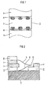
- FIG. 2 is a broken away sectional view of a cutout of the solar cell panel in FIG. 1, with a replacement solar cell prepared for priming;
- FIG. 3 is a broken away sectional view of a solar panel prepared according to the invention.
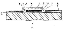
- FIG. 1 The broken away portion of a solar cell panel 1 illustrated in FIG. 1 shows a defective solar cell 2 and its electrical integration between two adjacent intact solar cells 3 and 4 .
- solar cells are particularly also solar cell assemblies (SCAs) consisting of a solar cell, a solar cell connector and cover glass.
- SCAs solar cell assemblies
- the electrical series connection of the solar cells takes place in a known manner by means of n-connectors 5 and p-connectors 6 , several connectors in each case being combined to a welding island. (In the illustrated embodiment, these are 4 n- or p-connectors per welding island.)
- a plurality of solar cells can also be provided in each case; for example, a complete solar cell module or a solar cell string or another defined grouped plurality of solar cells.
- a repaired solar cell panel 1 corresponding to the present invention is illustrated in FIG. 3 and will be explained in greater detail hereinafter.
- Such a repaired solar cell panel 1 can then, for example, be produced as follows:
- the solar cell panel 1 is covered by means of a Kapton foil which is cut out over the defective solar cell or cells 2 .
- the window edges of the Kapton foil are glued, for example, by means of an adhesive tape onto the adjacent intact solar cells 3 , 4 .
- the n- and p-connectors are exposed at the defective solar cell or cells 2 .
- the cover glass 7 can be partially removed over the welding islands of the n-connectors 5 .
- the defective solar cell or cells 2 may be partially removed, starting from the cover glass down to the p-connectors 6 in the area of the welding islands.
- the webs of the exposed n- and p-connectors are separated and bent up.
- the one or more replacement solar cells or replacement SCAs 8 may then be deposited (upside down, as shown in FIG. 2) with their cover glass 7 first on the cover glass of adjacent intact solar cells 3 or 4 , and temporarily fixed there by means of an adhesive tape.
- the replacement solar cells 8 are provided with standard-type n- and p-connectors.
- the n-connectors 5 (for example) of the replacement solar cells or replacement SCAs 8 are connected with the p-connectors 6 of intact solar cells (in FIG. 2, for example, solar cell 3 ) by means of a spot weld 9 .
- the p-side of the replacement solar cells or replacement SCAs 8 and the surface of the cover glass 7 of the defective one or several solar cells 2 is primed; that is, a pretreatment takes place by means of a primer.
- a bonding agent is applied to the primed surface of the defective solar cell or solar cells 2 .
- the bonding agent may, for example, be a silicone bonding agent, such as a silicone rubber.
- a special example of such a silicone rubber is the product “RTV-S691” of Wacker Co.
- the one or more replacement solar cells 8 are then turned over and placed by means of the p-side onto the defective solar cell or cells 2 and aligned there. After the hardening of the bonding agent, the p-connectors 6 of the replacement solar cell or cells 8 are connected with the n-connectors 5 of another adjacent intact solar cell 4 by way of a weld point 10 .
- FIG. 3 shows a repaired solar cell panel 1 according to the invention, as obtained particularly as a result of an above-described repair operation.
- One or more replacement solar cells or replacement SCAs 8 are glued by means of a silicone bonding agent onto one or more defective solar cells or SCAs 2 , and the n- and p-connectors 5 and 6 of the one or several replacement solar cells or replacement SCAs 8 are correspondingly connected with the p- and n-connectors 5 and 6 of the adjacent intact solar cells 3 , 4 by way of weld points 9 , 10 .
- the repaired solar cell panel 1 as well as the other intact solar cells 3 , 4 suffer no damage such as may occur in the known repair processes.
- the repair site in the area of the defective solar cell or cells 2 represents virtually no impairment of the functionality of the solar cell panel 1 .
Landscapes
- Engineering & Computer Science (AREA)
- Life Sciences & Earth Sciences (AREA)
- Sustainable Development (AREA)
- Remote Sensing (AREA)
- Aviation & Aerospace Engineering (AREA)
- Photovoltaic Devices (AREA)
Abstract
In a method of repairing a solar panel having a defective solar cell or cells, a replacement cell (or cells) is glued onto a defective solar cell or cells of the solar panel, and is electrically integrated in the solar panel.
Description
- This application claims the priority of German patent document 101 30 441.1, filed Aug. 10, 2001, the disclosure of which is expressly incorporated by reference herein, and is a Continuation-In-Part of U.S. patent application Ser. No. 10/214,729, filed Aug. 9, 2002.
- The invention relates to a method for repairing solar a cell panel.
- Heretofore, the repair of a solar cell panel with one or more defective solar cells, solar cell modules or solar cell strings has conventionally been accomplished by the complete removal and replacement of the defective cell or cells (sometimes referred to as a solar cell array), as described, for example, in German Patent Document DE 1 927 387. Moreover, German Patent Document DE 2 113 410 describes a repair-friendly arrangement of solar cells, in which a defective cell can easily be removed from a module or string of solar cells. Furthermore, German Patent Document DE 195 39 699 C2 describes the utilization of defective solar modules of a laminated construction, in which the solar cells are delaminated and the solar cell module is disassembled into its components. This state of the art in each case requires a relatively high-expenditure intrusion into the solar cell panel or into the solar cells, such that the resulting repaired solar cell panels may suffer damage.
- The known repair methods according to the state of the art may, for example, require the following steps: The cover glass over the one or more solar cells is removed at the welding islands of the top “n-connectors” of the solar cells to permit them to be separated and carefully bent up, exposing connection webs directly behind the welds. Subsequently, the defective one or more solar cells is or are removed from the solar cell panel, the “p-connector” being retained on the panel. Then, one or more solar cells having a special repair connector are inserted into the repair site and the projecting n- and p-connectors are welded to the adjacent solar cells. Such separation of the defective solar cell or cells, which also requires high expenditures, may result in damage to the panel structure as well as to adjoining solar cells. Moreover, the use of such repaired solar cell panels with possible damage is problematic, particularly for applications of solar panels which, after being placed in service, allow no simple further repair of solar cells, as, for example, for aerospace applications. In addition, special repair connectors are required for repaired solar cell panels according to the state of the art and a new insulation foil must be provided.
- It is an object of the present invention to provide a safe and effective method for repairing solar cell panels with defective solar cells, which does not have the disadvantages of the state of the art.
- This and other objects and advantages are achieved by the method according to the invention, which is based on the proposition that one or more defective solar cells, or solar cell strings, solar cell modules or another defined group of defective solar cells, continue to be physically part of the solar cell panel, and that these defective solar cells are not removed from the panel structure. (In this case, the term “solar cells” includes a solar cell “assembly” (SCAs) consisting of the solar cell, the solar cell connector and cover glass.)
- According to the invention, one or more replacement solar cells—also in the form of solar cell assemblies (SCAs)—are glued onto the defective solar cell or cells and are electrically integrated in the panel by means of the existing cut-open connectors. Therefore, either one defective solar cell may exist in the panel onto which the one or more intact replacement solar cells are glued, or several defective solar cells may be present which are directly adjoining, grouped or spatially separated (particularly in the form of entire solar cell strings or solar cell modules), onto which one or more intact replacement solar cells are glued. In cases in which complete defective solar cell strings, solar cell modules or other defined groups of solar cells are present, complete replacement solar cell strings or replacement solar cell modules can correspondingly be glued thereon.
- The invention achieves a saving of components and materials. Another important advantage is a reduction of the repair time that is required for producing such repaired solar cell panels, because the time consuming separation of the defective solar cells is eliminated, only the connectors needing to be exposed.
- A further embodiment of the invention provides that the one or more replacement solar cells are provided with standard-type n-connectors and p-connectors which are electrically connected (particularly welded) to cut-open connectors of one or more adjacent intact solar cells. The replacement solar cells may be glued on by means of a silicone glue.
- Specifically, the present invention can be used in the case of solar cell panels that are constructed for aerospace applications (for example, solar cell panels for satellites or other spacecraft). In every case, the use of repaired solar cell panels will be more cost-effective than, for example, a complete elimination of solar cell panels because of some defective solar cells.
- In order to apply the one or more replacement solar cells to the defective solar cell or the cells as described above, a protective cover foil can be used. For this purpose, the solar cell panel is covered by a Kapton foil with a window cut out adjacent the defective solar cell or cells. The window edges of the foil are preferably glued by means of adhesive tape, onto the adjacent intact solar cells in such a manner that the latter solar cells are protected by the foil during the repair operation. This process step is therefore advisable when special protection of the adjacent solar cells must be ensured.
- Other objects, advantages and novel features of the present invention will become apparent from the following detailed description of the invention when considered in conjunction with the accompanying drawings.
- FIG. 1 is a broken away view of a cutout of a solar cell panel with a defective solar cell;
- FIG. 2 is a broken away sectional view of a cutout of the solar cell panel in FIG. 1, with a replacement solar cell prepared for priming; and
- FIG. 3 is a broken away sectional view of a solar panel prepared according to the invention.
- The broken away portion of a
solar cell panel 1 illustrated in FIG. 1 shows a defectivesolar cell 2 and its electrical integration between two adjacent intactsolar cells 3 and 4. Here, solar cells are particularly also solar cell assemblies (SCAs) consisting of a solar cell, a solar cell connector and cover glass. The electrical series connection of the solar cells takes place in a known manner by means of n-connectors 5 and p-connectors 6, several connectors in each case being combined to a welding island. (In the illustrated embodiment, these are 4 n- or p-connectors per welding island.) The solar cells illustrated in FIG. 1, for example, each have three welding islands for n- and p-connectors. However, instead of individualsolar cells - A repaired
solar cell panel 1 corresponding to the present invention is illustrated in FIG. 3 and will be explained in greater detail hereinafter. Such a repairedsolar cell panel 1 can then, for example, be produced as follows: - First, the
solar cell panel 1 is covered by means of a Kapton foil which is cut out over the defective solar cell orcells 2. The window edges of the Kapton foil are glued, for example, by means of an adhesive tape onto the adjacent intactsolar cells 3, 4. Subsequently, the n- and p-connectors are exposed at the defective solar cell orcells 2. For this purpose, for example, thecover glass 7 can be partially removed over the welding islands of the n-connectors 5. In this case, on the welding islands of the p-connectors 6, the defective solar cell orcells 2 may be partially removed, starting from the cover glass down to the p-connectors 6 in the area of the welding islands. The webs of the exposed n- and p-connectors are separated and bent up. - At the repair site prepared in this manner, preferably the one or more replacement solar cells or
replacement SCAs 8 may then be deposited (upside down, as shown in FIG. 2) with theircover glass 7 first on the cover glass of adjacent intactsolar cells 3 or 4, and temporarily fixed there by means of an adhesive tape. - The replacement
solar cells 8 are provided with standard-type n- and p-connectors. The n-connectors 5 (for example) of the replacement solar cells orreplacement SCAs 8 are connected with the p-connectors 6 of intact solar cells (in FIG. 2, for example, solar cell 3) by means of aspot weld 9. - Subsequently, the p-side of the replacement solar cells or
replacement SCAs 8 and the surface of thecover glass 7 of the defective one or severalsolar cells 2 is primed; that is, a pretreatment takes place by means of a primer. After the primer has evaporated, a bonding agent is applied to the primed surface of the defective solar cell orsolar cells 2. The bonding agent may, for example, be a silicone bonding agent, such as a silicone rubber. A special example of such a silicone rubber is the product “RTV-S691” of Wacker Co. - The one or more replacement
solar cells 8 are then turned over and placed by means of the p-side onto the defective solar cell orcells 2 and aligned there. After the hardening of the bonding agent, the p-connectors 6 of the replacement solar cell orcells 8 are connected with the n-connectors 5 of another adjacent intact solar cell 4 by way of aweld point 10. - FIG. 3 shows a repaired
solar cell panel 1 according to the invention, as obtained particularly as a result of an above-described repair operation. One or more replacement solar cells orreplacement SCAs 8 are glued by means of a silicone bonding agent onto one or more defective solar cells orSCAs 2, and the n- and p-connectors replacement SCAs 8 are correspondingly connected with the p- and n-connectors solar cells 3, 4 by way ofweld points solar cell panel 1 as well as the other intactsolar cells 3, 4 suffer no damage such as may occur in the known repair processes. The repair site in the area of the defective solar cell orcells 2 represents virtually no impairment of the functionality of thesolar cell panel 1. - The foregoing disclosure has been set forth merely to illustrate the invention and is not intended to be limiting. Since modifications of the disclosed embodiments incorporating the spirit and substance of the invention may occur to persons skilled in the art, the invention should be construed to include everything within the scope of the appended claims and equivalents thereof.
Claims (11)
1. A method of repairing a solar panel comprising a plurality of mutually electrically connected solar cells, said method comprising:
gluing at least one replacement solar cell onto at least one defective solar cell of the solar panel; and
electrically connecting the glued on at least one replacement solar cell to the solar panel.
2. The method according to claim 1 , wherein
the at least one replacement solar cell includes standard n-connectors and p-connectors; and
said electrically connecting comprises welding the n- and p-connectors of the at least one replacement solar cell to cut-open connectors of an adjacent intact solar cell arrays.
3. The method according to claim 1 , wherein silicone bonding agent is used for gluing on the at least one replacement solar cell.
4. The method according to claim 1 , wherein a protective cover foil is first applied to solar cells adjoining the at least one defective solar cell array.
5. A method for repairing a solar panel comprising a matrix of individual solar cells, each having a plurality of n-connectors and p-connectors and being covered by a layer of cover glass, said method comprising:
removing the cover glass adjacent welding islands of n- and p-connectors for a defective solar cell group in said solar panel;
gluing a replacement solar cell group onto the defective solar cell group; and
electrically connecting connectors of the replacement solar cell group to connectors of solar cells in said panel adjacent said defective solar cell group.
6. The method according to claim 5 , wherein:
said defective solar cell group comprises at least one solar cell; and
said replacement solar cell group comprises at least one solar cell.
7. A method for repairing a solar panel comprising a matrix of individual solar cells, each having a plurality of n-connectors and p-connectors and being covered by a layer of cover glass, said method comprising:
removing the cover glass adjacent welding islands of n- and p-connectors for a defective solar cell group in said solar panel, whereby said connectors are exposed;
cutting the exposed connectors for said defective solar cell group and bending them upwards;
placing a replacement solar cell group upside down adjacent the defective solar cell group;
connecting exposed n- or p-type connectors on the replacement solar cell array to connectors on a first solar cell adjacent the defective solar cell;
folding the replacement solar cell group over and bonding it to unremoved glass covering the defective solar cell group; and
connecting remaining exposed connectors of said replacement solar cell group to connectors of a second solar cell adjacent the defective solar cell group.
8. The method according to claim 7 , wherein
said defective solar cell group comprises at least one solar cell; and
said replacement solar cell group comprises at least one solar cell.
9. A repaired solar cell panel comprising:
a plurality of mutually electrically connected solar cells; and
a replacement solar cell group glued onto a defective solar cell group of the solar cell panel and electrically integrated in the solar cell panel.
10. The solar repaired cell panel according to claim 1 , wherein the replacement solar cell group has standard-type n-connectors and p-connectors which are welded to cut-open connections of adjacent intact solar cells.
11. The solar repaired cell panel according to claim 1 , wherein the replacement solar cell group is glued with a silicon bonding agent.
Priority Applications (1)
| Application Number | Priority Date | Filing Date | Title |
|---|---|---|---|
| US10/326,273 US6809250B2 (en) | 2001-08-10 | 2002-12-23 | Repaired solar panel and method of preparing same |
Applications Claiming Priority (5)
| Application Number | Priority Date | Filing Date | Title |
|---|---|---|---|
| DE10139441A DE10139441C1 (en) | 2001-08-10 | 2001-08-10 | Method for repairing solar panels comprises placing protective sheet over intact arrays, replacement array then being glued over defective array and welded connections made to intact arrays |
| DE10130441.1 | 2001-08-10 | ||
| DE10130441 | 2001-08-10 | ||
| US10/214,729 US20030029036A1 (en) | 2001-08-10 | 2002-08-09 | Method of repairing a solar panel |
| US10/326,273 US6809250B2 (en) | 2001-08-10 | 2002-12-23 | Repaired solar panel and method of preparing same |
Related Parent Applications (1)
| Application Number | Title | Priority Date | Filing Date |
|---|---|---|---|
| US10/214,729 Continuation-In-Part US20030029036A1 (en) | 2001-08-10 | 2002-08-09 | Method of repairing a solar panel |
Publications (2)
| Publication Number | Publication Date |
|---|---|
| US20030196691A1 true US20030196691A1 (en) | 2003-10-23 |
| US6809250B2 US6809250B2 (en) | 2004-10-26 |
Family
ID=29251742
Family Applications (1)
| Application Number | Title | Priority Date | Filing Date |
|---|---|---|---|
| US10/326,273 Expired - Fee Related US6809250B2 (en) | 2001-08-10 | 2002-12-23 | Repaired solar panel and method of preparing same |
Country Status (1)
| Country | Link |
|---|---|
| US (1) | US6809250B2 (en) |
Cited By (3)
| Publication number | Priority date | Publication date | Assignee | Title |
|---|---|---|---|---|
| US20030029036A1 (en) * | 2001-08-10 | 2003-02-13 | Astrium Gmbh | Method of repairing a solar panel |
| US20100193007A1 (en) * | 2009-02-05 | 2010-08-05 | Chun-Hsiung Lu | Thin Film Solar Cell Module And Method For Repairing The Same |
| US20160118523A1 (en) * | 2014-10-27 | 2016-04-28 | Lg Electronics Inc. | Solar cell module and method and device for repairing the same |
Families Citing this family (10)
| Publication number | Priority date | Publication date | Assignee | Title |
|---|---|---|---|---|
| US8227688B1 (en) | 2005-10-17 | 2012-07-24 | Solaria Corporation | Method and resulting structure for assembling photovoltaic regions onto lead frame members for integration on concentrating elements for solar cells |
| US7910822B1 (en) | 2005-10-17 | 2011-03-22 | Solaria Corporation | Fabrication process for photovoltaic cell |
| US7910392B2 (en) | 2007-04-02 | 2011-03-22 | Solaria Corporation | Method and system for assembling a solar cell package |
| US20090056806A1 (en) * | 2007-09-05 | 2009-03-05 | Solaria Corporation | Solar cell structure including a plurality of concentrator elements with a notch design and predetermined radii and method |
| US8119902B2 (en) | 2007-05-21 | 2012-02-21 | Solaria Corporation | Concentrating module and method of manufacture for photovoltaic strips |
| US7419377B1 (en) * | 2007-08-20 | 2008-09-02 | Solaria Corporation | Electrical coupling device and method for solar cells |
| US7910035B2 (en) | 2007-12-12 | 2011-03-22 | Solaria Corporation | Method and system for manufacturing integrated molded concentrator photovoltaic device |
| JP5436901B2 (en) * | 2009-03-23 | 2014-03-05 | 三洋電機株式会社 | Manufacturing method of solar cell module |
| USD699176S1 (en) | 2011-06-02 | 2014-02-11 | Solaria Corporation | Fastener for solar modules |
| US11575056B1 (en) | 2020-07-15 | 2023-02-07 | The Boeing Company | Repairing a solar cell bonded on a flexible circuit |
Citations (9)
| Publication number | Priority date | Publication date | Assignee | Title |
|---|---|---|---|---|
| US4057439A (en) * | 1976-08-25 | 1977-11-08 | Solarex Corporation | Solar panel |
| US4675067A (en) * | 1984-06-13 | 1987-06-23 | The United States Of America As Represented By The Secretary Of The Air Force | Solar cell coverslide extraction apparatus |
| US5006179A (en) * | 1989-05-24 | 1991-04-09 | Solarex Corporation | Interconnect for electrically connecting solar cells |
| US5021099A (en) * | 1988-08-09 | 1991-06-04 | The Boeing Company | Solar cell interconnection and packaging using tape carrier |
| US5118361A (en) * | 1990-05-21 | 1992-06-02 | The Boeing Company | Terrestrial concentrator solar cell module |
| US6294724B1 (en) * | 1999-01-14 | 2001-09-25 | Canon Kabushiki Kaisha | Solar cell module and power generation apparatus |
| US20030029036A1 (en) * | 2001-08-10 | 2003-02-13 | Astrium Gmbh | Method of repairing a solar panel |
| US6617505B2 (en) * | 2000-11-21 | 2003-09-09 | Sharp Kabushiki Kaisha | Solar battery module, replacement solar cell, and method of replacing solar cell |
| US20040003840A1 (en) * | 2002-06-06 | 2004-01-08 | Sharp Kabushiki Kaisha | Method for regenerating photovoltaic module and photovoltaic module |
Family Cites Families (3)
| Publication number | Priority date | Publication date | Assignee | Title |
|---|---|---|---|---|
| DE1927387C3 (en) | 1969-05-29 | 1978-08-17 | Messerschmitt-Boelkow-Blohm Gmbh, 8000 Muenchen | Solar battery |
| DE19539699C2 (en) | 1995-10-25 | 1998-03-19 | Siemens Solar Gmbh | Process for recycling defective, laminated solar modules |
| JP2003017731A (en) * | 2001-06-29 | 2003-01-17 | Canon Inc | Repair method for solar cell module array and solar cell module array |
-
2002
- 2002-12-23 US US10/326,273 patent/US6809250B2/en not_active Expired - Fee Related
Patent Citations (9)
| Publication number | Priority date | Publication date | Assignee | Title |
|---|---|---|---|---|
| US4057439A (en) * | 1976-08-25 | 1977-11-08 | Solarex Corporation | Solar panel |
| US4675067A (en) * | 1984-06-13 | 1987-06-23 | The United States Of America As Represented By The Secretary Of The Air Force | Solar cell coverslide extraction apparatus |
| US5021099A (en) * | 1988-08-09 | 1991-06-04 | The Boeing Company | Solar cell interconnection and packaging using tape carrier |
| US5006179A (en) * | 1989-05-24 | 1991-04-09 | Solarex Corporation | Interconnect for electrically connecting solar cells |
| US5118361A (en) * | 1990-05-21 | 1992-06-02 | The Boeing Company | Terrestrial concentrator solar cell module |
| US6294724B1 (en) * | 1999-01-14 | 2001-09-25 | Canon Kabushiki Kaisha | Solar cell module and power generation apparatus |
| US6617505B2 (en) * | 2000-11-21 | 2003-09-09 | Sharp Kabushiki Kaisha | Solar battery module, replacement solar cell, and method of replacing solar cell |
| US20030029036A1 (en) * | 2001-08-10 | 2003-02-13 | Astrium Gmbh | Method of repairing a solar panel |
| US20040003840A1 (en) * | 2002-06-06 | 2004-01-08 | Sharp Kabushiki Kaisha | Method for regenerating photovoltaic module and photovoltaic module |
Cited By (4)
| Publication number | Priority date | Publication date | Assignee | Title |
|---|---|---|---|---|
| US20030029036A1 (en) * | 2001-08-10 | 2003-02-13 | Astrium Gmbh | Method of repairing a solar panel |
| US20100193007A1 (en) * | 2009-02-05 | 2010-08-05 | Chun-Hsiung Lu | Thin Film Solar Cell Module And Method For Repairing The Same |
| US20160118523A1 (en) * | 2014-10-27 | 2016-04-28 | Lg Electronics Inc. | Solar cell module and method and device for repairing the same |
| US9978899B2 (en) * | 2014-10-27 | 2018-05-22 | Lg Electronics Inc. | Solar cell module and method and device for repairing the same |
Also Published As
| Publication number | Publication date |
|---|---|
| US6809250B2 (en) | 2004-10-26 |
Similar Documents
| Publication | Publication Date | Title |
|---|---|---|
| US6617505B2 (en) | Solar battery module, replacement solar cell, and method of replacing solar cell | |
| US6809250B2 (en) | Repaired solar panel and method of preparing same | |
| US6799742B2 (en) | Solar panel for space and method for manufacturing the same | |
| US7271333B2 (en) | Apparatus and method of production of thin film photovoltaic modules | |
| US20030029036A1 (en) | Method of repairing a solar panel | |
| US20100216276A1 (en) | Method for Electrically Connecting Photovoltaic Cells in a Photovoltaic Device | |
| EP3329521B1 (en) | Solar array system and method of manufacturing | |
| US20040182432A1 (en) | Photovoltaic module subassembly and photovoltaic module with sealed insulating glass | |
| EP4273940B1 (en) | Power routing module for a solar cell array | |
| EP3297041B1 (en) | Power routing module for a solar cell array | |
| CN1311901A (en) | Flexible, folable solar generator for spacecrafts | |
| US5948175A (en) | Strap device clamping soldered wires for use in solar cell arrays | |
| WO2025202078A1 (en) | Method of forming a photovoltaic device and the photovoltaic device | |
| EP0984496B1 (en) | Manufacturing method for a solar cell having a protection diode | |
| JP4085304B2 (en) | Manufacturing method of solar cell module | |
| JP3605998B2 (en) | Solar cell module and method of manufacturing the same | |
| NL2026389B1 (en) | Method for producing a multitude of electrically interconnected photovoltaic cells. | |
| JP2934366B2 (en) | Solar cells with interconnectors | |
| JP2007201291A (en) | Regeneration method of solar cell module and solar cell module | |
| JP2004152829A (en) | Solar cell module and method of manufacturing the same | |
| US20250022975A1 (en) | Solar panel using back-contacted solar cells | |
| KR20210036094A (en) | Method for repairing crystalline solar cell module using separation mask | |
| JPS63275186A (en) | Solar cell array | |
| JP2022019636A (en) | Repairing solar cell bonded onto flexible circuit | |
| WO2025186978A1 (en) | Solar cell panel, solar cell module, solar cell panel production method, solar cell paddle, and artificial satellite |
Legal Events
| Date | Code | Title | Description |
|---|---|---|---|
| AS | Assignment |
Owner name: ASTRIUM GMBH, GERMANY Free format text: ASSIGNMENT OF ASSIGNORS INTEREST;ASSIGNOR:GERSON, REINER;REEL/FRAME:014091/0691 Effective date: 20030306 |
|
| FPAY | Fee payment |
Year of fee payment: 4 |
|
| FPAY | Fee payment |
Year of fee payment: 8 |
|
| REMI | Maintenance fee reminder mailed | ||
| LAPS | Lapse for failure to pay maintenance fees | ||
| STCH | Information on status: patent discontinuation |
Free format text: PATENT EXPIRED DUE TO NONPAYMENT OF MAINTENANCE FEES UNDER 37 CFR 1.362 |
|
| STCH | Information on status: patent discontinuation |
Free format text: PATENT EXPIRED DUE TO NONPAYMENT OF MAINTENANCE FEES UNDER 37 CFR 1.362 |
|
| FP | Lapsed due to failure to pay maintenance fee |
Effective date: 20161026 |