US20030196481A1 - Combustion state detection apparatus - Google Patents
Combustion state detection apparatus Download PDFInfo
- Publication number
- US20030196481A1 US20030196481A1 US10/261,502 US26150202A US2003196481A1 US 20030196481 A1 US20030196481 A1 US 20030196481A1 US 26150202 A US26150202 A US 26150202A US 2003196481 A1 US2003196481 A1 US 2003196481A1
- Authority
- US
- United States
- Prior art keywords
- signal
- failure determination
- ion current
- section
- ignition coil
- Prior art date
- Legal status (The legal status is an assumption and is not a legal conclusion. Google has not performed a legal analysis and makes no representation as to the accuracy of the status listed.)
- Granted
Links
Images


Classifications
-
- G—PHYSICS
- G01—MEASURING; TESTING
- G01L—MEASURING FORCE, STRESS, TORQUE, WORK, MECHANICAL POWER, MECHANICAL EFFICIENCY, OR FLUID PRESSURE
- G01L23/00—Devices or apparatus for measuring or indicating or recording rapid changes, such as oscillations, in the pressure of steam, gas, or liquid; Indicators for determining work or energy of steam, internal-combustion, or other fluid-pressure engines from the condition of the working fluid
- G01L23/22—Devices or apparatus for measuring or indicating or recording rapid changes, such as oscillations, in the pressure of steam, gas, or liquid; Indicators for determining work or energy of steam, internal-combustion, or other fluid-pressure engines from the condition of the working fluid for detecting or indicating knocks in internal-combustion engines; Units comprising pressure-sensitive members combined with ignitors for firing internal-combustion engines
-
- F—MECHANICAL ENGINEERING; LIGHTING; HEATING; WEAPONS; BLASTING
- F02—COMBUSTION ENGINES; HOT-GAS OR COMBUSTION-PRODUCT ENGINE PLANTS
- F02P—IGNITION, OTHER THAN COMPRESSION IGNITION, FOR INTERNAL-COMBUSTION ENGINES; TESTING OF IGNITION TIMING IN COMPRESSION-IGNITION ENGINES
- F02P17/00—Testing of ignition installations, e.g. in combination with adjusting; Testing of ignition timing in compression-ignition engines
- F02P17/12—Testing characteristics of the spark, ignition voltage or current
- F02P2017/125—Measuring ionisation of combustion gas, e.g. by using ignition circuits
Definitions
- This invention relates to a combustion state detection apparatus of an internal combustion engine for detecting a combustion state of the internal combustion engine by an ion current flowing as a medium of an ion occurring by combustion in the internal combustion engine.
- FIG. 7 is a block diagram showing a configuration of an apparatus according to the related art.
- FIG. 8 is a timing chart showing an operation thereof.
- Numeral 1 denotes a control unit.
- Numeral 1 a denotes an ion current detection circuit for converting an ion current into a voltage value, including a current mirror and a resistor for ion current detection.
- Numeral 1 b denotes a mask circuit for eliminating a noise signal superimposed on the ion current at the time of turning on an ignition signal and after the completion of discharge.
- Numeral 1 c denotes combustion/misfire determination section for comparing a signal after mask with a predetermined reference level (Vref 1 ) and making a combustion determination when the signal is larger than the reference level or making a misfire determination when the signal is smaller than the reference level.
- Numeral 1 d denotes an ignition signal generation section.
- Numeral 1 g denotes a failure content determination section.
- Numeral 2 denotes an ignition coil.
- Numeral 2 a denotes a primary winding of the ignition coil.
- Numeral 2 b denotes a secondary winding of the ignition coil.
- Numeral 2 c denotes a drive circuit including a preamplifier and a switching element.
- Numeral 2 d denotes a bias circuit including a capacitor for storing a bias voltage for ion current detection, a Zener diode for defining a bias voltage value and a diode for forming a secondary current path.
- Numeral 3 denotes a spark plug.
- the drive circuit By an ignition signal (signal A) outputted by the ignition signal generation section, the drive circuit energizes and breaks a primary current flowing through a primary winding of the ignition coil. At a time of the break, a high voltage occurs in a secondary winding of the ignition coil and a discharge is performed between electrodes of the spark plug and combustion of mixed gas inside a cylinder (not shown) is performed.
- the capacitor inside the bias circuit is charged by a secondary current flowing through a secondary winding during the discharge, and this charge voltage is applied to the spark plug after the completion of the discharge, and an ion current flows using an ion occurring by the combustion as a medium.
- This ion current is converted into a voltage by the ion current detection circuit in the control unit (signal B), and noise occurring at the time of turning on the ignition signal and after the completion of the discharge is eliminated by the mask circuit (signal C), and the combustion/misfire determination section makes a combustion determination when a signal level after mask is larger than a predetermined level (Vref 1 ), or makes a misfire determination when the signal level is smaller than the level.
- a signal after mask at the time of misfire is indicated as shown in FIG. 8 and it can be determined whether or not the mixed gas has burned, but in the case of the misfire, a failure cause bringing about the misfire and a failure part cannot be identified. Also, in the case of failure of a detection system (ex. a break in wiring between the bias circuit and the ion current detection circuit), the signal after mask becomes equal to that at the time of the misfire. Because of this, when misfire detection is performed by the conventional apparatus and a misfire determination is made, there is a problem that it is necessary to inspect all the parts and detection systems having the possibility of causing the misfire for the purpose of repair and the number of man-hours of the repair is large.
- a combustion state detection apparatus of an internal combustion engine for identifying a failure part and reducing the number of man-hours of repair is provided.
- a combustion state detection apparatus including an ignition coil, an ignition coil primary current switching section, an ion current detection section, a failure determination signal output section, an ion current detection signal output section, a combustion state detection section, and a failure determination section.
- the ion current detection section detects an ion current.
- the failure determination signal output section outputs a failure determination signal of an ignition operation.
- the ion current detection signal output section outputs an ion current detection signal including the ion current and the failure determination signal.
- the combustion state detection section detects a combustion state of an internal combustion engine based on the ion current detection signal.
- the failure determination section determines failure of the ignition coil based on the ion current detection signal.
- a combustion state detection apparatus including an ignition coil, an ignition coil primary current switching section, an ion current detection section, a failure determination signal output section, an ion current detection signal, a second failure determination signal output section, a combustion state detection section, a failure determination section, and a second failure determination section.
- the ion current detection section detects an ion current.
- the failure determination signal output section outputs a failure determination signal of an ignition operation.
- the ion current detection signal output section outputs an ion current detection signal including the ion current and the failure determination signal.
- the second failure determination signal output section outputs a second failure determination signal of an ignition operation.
- the combustion state detection section detects a combustion state of an internal combustion engine based on the ion current detection signal.
- the failure determination section determines failure of the ignition coil based on the ion current detection signal.
- the second failure determination section determines failure of the ignition coil based on the second failure determination signal.
- FIG. 1 is a block diagram showing a first embodiment
- FIG. 2 is a timing chart showing the first embodiment
- FIG. 3 is a block diagram showing a second embodiment
- FIG. 4 is a timing chart showing the second embodiment
- FIG. 5 is a block diagram showing a third embodiment
- FIG. 6 is a timing chart showing the third embodiment
- FIG. 7 is a block diagram showing a conventional apparatus.
- FIG. 8 is a timing chart showing the conventional apparatus.
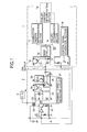
- FIG. 1 is a block diagram showing one embodiment of the invention.
- FIG. 2 is a timing chart showing an operation thereof.
- Numeral 1 denotes a control unit.
- Numeral 1 a denotes an ion current detection circuit for converting an ion current into a voltage value, including a current mirror and a resistor for ion current detection.
- Numeral 1 b denotes a mask circuit for eliminating a noise signal superimposed on the ion current at a time of turning on an ignition signal and after the completion of discharge.
- Numeral 1 c denotes a combustion/misfire determination section for comparing a signal after mask with a predetermined reference level (Vref 1 ) and making a combustion determination when the signal is larger than the reference level or making a misfire determination when the signal is smaller than the reference level.
- Numeral 1 d denotes an ignition signal generation section.
- Numeral 1 e denotes a failure determination section for making a determination of failure based on the signal after mask.
- Numeral 2 denotes an ignition coil.
- Numeral 2 a denotes a primary winding of the ignition coil.
- Numeral 2 b denotes a secondary winding of the ignition coil.
- Numeral 2 c denotes a drive circuit including a preamplifier, a switching element, and a primary current detection resistor.
- Numeral 2 d denotes a bias circuit including a capacitor for storing a bias voltage for ion current detection, a Zener diode for defining a bias voltage value, and a diode for forming a secondary current path.
- Numeral 2 e denotes a current mirror circuit for distributing the ion current.
- Numeral 2 f denotes a primary current detection circuit for detecting a period during which a primary current exceeds a predetermined level Vref 3 based on a voltage drop occurring in the primary current detection resistor in the drive circuit and producing a High output (base current supply) only for the period.
- Numeral 2 g denotes a constant-current circuit for supplying a constant current I 1 at a time when the primary current detection circuit produces the High output, and forms a failure determination signal output section along with numeral 2 f.
- Numeral 2 h denotes a current mirror circuit for outputting a current in which the ion current and the constant current of primary current detection are added (in the embodiment, a current is pulled from the control unit) and forms an ion current detection signal output section.
- Numeral 3 denotes a spark plug.
- the primary current detection circuit supplies a base current to the constant-current circuit.
- a constant current is supplied to the current mirror circuit 2 h by the constant-current circuit.
- an ion current is supplied to the current mirror circuit 2 h by the current mirror circuit 2 e . Therefore, a current pulled from the control unit by the current mirror circuit 2 h is sum of the ion current and the constant current.
- An ion output signal is indicated as C shown in FIG. 2.
- the mask circuit masks an ion output signal for a predetermined period from signal occurrence and a signal after mask is indicated as shown in D.
- a failure determination signal (corresponding to the constant current flowing by primary current detection) occurs only for a period during which a primary current flows, the period is a period during which an ignition signal is High. This period is set to a failure determination period.
- the failure determination section makes a normal determination when an output after mask exceeds a predetermined level Vref 2 or makes an abnormal determination when the output does not exceed the level Vref 2 .
- the combustion/misfire determination section makes a combustion determination when the output after mask. exceeds the predetermined level Vref 1 or makes an abnormal determination when the output does not exceed the level Vref 1 .
- signals of the predetermined level or more are not identified in both of the failure determination period and the combustion determination period. In this case, there is a possibility that the primary current of the ignition coil has not flowed. A break in at least one of VB, GND and an ignition signal of the ignition coil or circuit failure including a primary winding drive circuit is given as the cause.
- a determination of the failure contents as described above can be made by a failure content determination section 1 g . Also, a person can made the determination based on output (display) of the combustion/misfire determination section 1 c and the failure determination section 1 e.
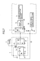
- FIG. 3 is a block diagram showing a second embodiment.
- FIG. 4 is a timing chart showing an operation thereof.
- Numeral 1 denotes a control unit.
- Numeral 1 a denotes an ion current detection circuit for converting an ion current into a voltage value, including a current mirror and a resistor for ion current detection.
- Numeral 1 b denotes a mask circuit for eliminating a noise signal superimposed on the ion current at a time of turning on an ignition signal and after the completion of discharge.
- Numeral 1 c denotes combustion/misfire a determination section for comparing a signal after mask with a predetermined reference level (Vref 1 ) and making a combustion determination when the signal is larger than the reference level or making a misfire determination when the signal is smaller than the reference level.
- Numeral 1 e denotes a failure determination section for making a determination of failure based on the signal after mask.
- Numeral 2 denotes an ignition coil.
- Numeral 2 a denotes a primary winding of the ignition coil.
- Numeral 2 b denotes a secondary winding of the ignition coil.
- Numeral 2 c denotes a drive circuit including a preamplifier, a switching element, and a primary current detection resistor.
- Numeral 2 d denotes a bias circuit including a capacitor for storing a bias voltage for ion current detection, a Zener diode for defining a bias voltage value, and a diode for forming a secondary current path.
- Numeral 2 e denotes a current mirror circuit for distributing the ion current.
- Numeral 2 f denotes a primary current detection circuit for detecting a period during which a primary current exceeds a predetermined level Vref 3 based on a voltage drop occurring in the primary current detection resistor in the drive circuit and producing a High output (base current supply) only for the period.
- Numeral 2 g denotes a constant-current circuit for supplying a constant current I 1 at a time when the primary current detection circuit produces the High output.
- Numeral 2 h denotes a current mirror circuit for outputting a current in which the ion current and the constant current of primary current detection are added (in the embodiment, a current is pulled from the control unit).
- Numeral 3 denotes a spark plug.
- Numeral 4 denotes a primary current detection device connected in series with a VB line of the ignition coil.
- the primary current detection device includes a resistor for primary current detection, which generates a voltage drop due to a primary current, and a primary current detection circuit for determining that a primary current flows due to the voltage drop to generate a signal.
- the primary current detection device is added to the VB line of the ignition coil.
- An output signal of the primary current detection device is indicated as shown in a signal D of FIG. 4 .
- the cause of failure cannot be identified.
- the cause can be identified as a break in an ion output signal when the output signal of the primary current detection device is present.
- the cause can be identified as a break in at least one of VB, GND and an ignition signal of the ignition coil or circuit failure including a primary winding drive circuit when the output signal is absent.
- FIG. 5 is a block diagram showing a third embodiment.
- FIG. 6 is a timing chart showing an operation thereof.
- Numeral 1 denotes a control unit.
- Numeral 1 a denotes an ion current detection circuit for converting an ion current into a voltage value, including a current mirror and a resistor for ion current detection.
- Numeral 1 b denotes a mask circuit for eliminating a noise signal superimposed on the ion current at the time of turning on an ignition signal and after the completion of discharge.
- Numeral 1 c denotes combustion/misfire determination section for comparing a signal after mask with a predetermined reference level (Vref 1 ) and making a combustion determination when the signal is larger than the reference level or making a misfire determination when the signal is smaller than the reference level.
- Numeral 1 d denotes ignition signal generation section.
- Numeral 1 e denotes a failure determination section for making a determination of failure based on the signal after mask.
- Numeral 1 f denotes a failure determination section for determining the presence or absence of failure of ignition signal wiring.
- Numeral 2 denotes an ignition coil.
- Numeral 2 a denotes a primary winding of the ignition coil.
- Numeral 2 b denotes a secondary winding of the ignition coil.
- Numeral 2 c denotes a drive circuit including a preamplifier, a switching element and a primary current detection resistor.
- Numeral 2 d denotes a bias circuit including a capacitor for storing a bias voltage for ion current detection, a Zener diode for defining a bias voltage value and a diode for forming a secondary current path.
- Numeral 2 e denotes a current mirror circuit for distributing the ion current.
- Numeral 2 f denotes a primary current detection circuit for detecting a period during which a primary current exceeds a predetermined level Vref 3 based on a voltage drop occurring in the primary current detection resistor in the drive circuit and producing a High output (base current supply) only for the period.
- Numeral 2 g denotes a constant-current circuit for supplying a constant current I 1 at a time when the primary current detection circuit produces the High output.
- Numeral 2 h denotes a current mirror circuit for outputting a current in which the ion current and the constant current of primary current detection are added (in the embodiment, a current is pulled from the control unit).
- Numeral 2 i denotes an ignition signal detection circuit for producing a High output (base current supply) for a period during which an ignition signal is a High level.
- Numeral 2 j is a constant-current circuit for supplying a constant current I 2 at a time when the ignition signal detection circuit produces the High output.
- Numeral 3 is a spark plug.
- Numeral 4 denotes a primary current detection device connected in series with a VB line of the ignition coil.
- the primary current detection device includes a resistor for primary current detection, which generates a voltage drop due to a primary current, and a primary current detection circuit for determining that a primary current flows due to the voltage drop to generate a signal.
- the failure determination section is added to the control unit and the ignition signal detection section and the constant-current circuit are added to the ignition coil.
- the failure determination section in the control unit is specifically an A/D converter. It is configured that a processor determines whether or not a High level of an ignition signal decided by a pull-up resistor in the ignition signal generation section and a pull-down resistor in the ignition coil drive circuit is a normal voltage level by an A/D conversion result. However, in a case of implementing this configuration, it is required that there is a small potential difference between GNDs of the control unit and the ignition coil.
- the ignition signal detection section in the coil operates the constant-current circuit for a period during which an ignition signal is a High level and the constant current I 2 occurs in an ion output signal of FIG. 6.
- the leftmost signal of FIG. 6 is a case in which ignition is performed normally and combustion is performed normally.
- a signal in excess of Vref 4 occurs for a period during which the ignition signal is High and a signal of Vref 2 or more occurs in the later half of the ignition signal in which the primary current becomes high. Therefore, it is found that an ignition signal has been correctly transmitted to the drive circuit in the ignition coil and a primary current has flowed correctly. Also, an ion current of Vref 1 or more occurs for a combustion determination period. Therefore, it is found that the combustion has been performed correctly.
- the signal of Vref 4 or more is identified in the failure determination period.
- a signal in excess of Vref 2 cannot be identified and also the signal of Vref 1 or more is not identified in the combustion determination period.
- the ignition signal has been correctly transmitted to the ignition coil but the primary current has not flowed.
- a break in at least one of VB, GND and an ignition signal of the ignition coil or circuit failure including a primary winding drive circuit is given as the cause.
Landscapes
- Engineering & Computer Science (AREA)
- Chemical & Material Sciences (AREA)
- Combustion & Propulsion (AREA)
- Mechanical Engineering (AREA)
- General Engineering & Computer Science (AREA)
- Physics & Mathematics (AREA)
- General Physics & Mathematics (AREA)
- Ignition Installations For Internal Combustion Engines (AREA)
- Combined Controls Of Internal Combustion Engines (AREA)
- Testing Of Engines (AREA)
Abstract
Description
- 1. Field of the Invention
- This invention relates to a combustion state detection apparatus of an internal combustion engine for detecting a combustion state of the internal combustion engine by an ion current flowing as a medium of an ion occurring by combustion in the internal combustion engine.
- 2. Description of the Related Art
- FIG. 7 is a block diagram showing a configuration of an apparatus according to the related art. FIG. 8 is a timing chart showing an operation thereof.
-
Numeral 1 denotes a control unit. -
Numeral 1 a denotes an ion current detection circuit for converting an ion current into a voltage value, including a current mirror and a resistor for ion current detection. - Numeral 1 b denotes a mask circuit for eliminating a noise signal superimposed on the ion current at the time of turning on an ignition signal and after the completion of discharge.
- Numeral 1 c denotes combustion/misfire determination section for comparing a signal after mask with a predetermined reference level (Vref1) and making a combustion determination when the signal is larger than the reference level or making a misfire determination when the signal is smaller than the reference level.
-
Numeral 1 d denotes an ignition signal generation section. - Numeral 1 g denotes a failure content determination section.
-
Numeral 2 denotes an ignition coil. -
Numeral 2 a denotes a primary winding of the ignition coil. - Numeral 2 b denotes a secondary winding of the ignition coil.
- Numeral 2 c denotes a drive circuit including a preamplifier and a switching element.
-
Numeral 2 d denotes a bias circuit including a capacitor for storing a bias voltage for ion current detection, a Zener diode for defining a bias voltage value and a diode for forming a secondary current path. -
Numeral 3 denotes a spark plug. - By an ignition signal (signal A) outputted by the ignition signal generation section, the drive circuit energizes and breaks a primary current flowing through a primary winding of the ignition coil. At a time of the break, a high voltage occurs in a secondary winding of the ignition coil and a discharge is performed between electrodes of the spark plug and combustion of mixed gas inside a cylinder (not shown) is performed. The capacitor inside the bias circuit is charged by a secondary current flowing through a secondary winding during the discharge, and this charge voltage is applied to the spark plug after the completion of the discharge, and an ion current flows using an ion occurring by the combustion as a medium. This ion current is converted into a voltage by the ion current detection circuit in the control unit (signal B), and noise occurring at the time of turning on the ignition signal and after the completion of the discharge is eliminated by the mask circuit (signal C), and the combustion/misfire determination section makes a combustion determination when a signal level after mask is larger than a predetermined level (Vref 1), or makes a misfire determination when the signal level is smaller than the level.
- At a time-of combustion, a signal after mask at the time of misfire is indicated as shown in FIG. 8 and it can be determined whether or not the mixed gas has burned, but in the case of the misfire, a failure cause bringing about the misfire and a failure part cannot be identified. Also, in the case of failure of a detection system (ex. a break in wiring between the bias circuit and the ion current detection circuit), the signal after mask becomes equal to that at the time of the misfire. Because of this, when misfire detection is performed by the conventional apparatus and a misfire determination is made, there is a problem that it is necessary to inspect all the parts and detection systems having the possibility of causing the misfire for the purpose of repair and the number of man-hours of the repair is large.
- In the present application, a combustion state detection apparatus of an internal combustion engine for identifying a failure part and reducing the number of man-hours of repair is provided.
- According to a first aspect of the invention, there is provided a combustion state detection apparatus including an ignition coil, an ignition coil primary current switching section, an ion current detection section, a failure determination signal output section, an ion current detection signal output section, a combustion state detection section, and a failure determination section. The ion current detection section detects an ion current. The failure determination signal output section outputs a failure determination signal of an ignition operation. The ion current detection signal output section outputs an ion current detection signal including the ion current and the failure determination signal. The combustion state detection section detects a combustion state of an internal combustion engine based on the ion current detection signal. The failure determination section determines failure of the ignition coil based on the ion current detection signal.
- According to a second aspect of the invention, there is provided a combustion state detection apparatus including an ignition coil, an ignition coil primary current switching section, an ion current detection section, a failure determination signal output section, an ion current detection signal, a second failure determination signal output section, a combustion state detection section, a failure determination section, and a second failure determination section. The ion current detection section detects an ion current. The failure determination signal output section outputs a failure determination signal of an ignition operation. The ion current detection signal output section outputs an ion current detection signal including the ion current and the failure determination signal. The second failure determination signal output section outputs a second failure determination signal of an ignition operation. The combustion state detection section detects a combustion state of an internal combustion engine based on the ion current detection signal. The failure determination section determines failure of the ignition coil based on the ion current detection signal. The second failure determination section determines failure of the ignition coil based on the second failure determination signal.
- According to the invention, since failure parts can be identified or limited, there is shown a practically remarkable effect capable of reducing number of man-hours of inspection items in a case of making repairs.
- FIG. 1 is a block diagram showing a first embodiment;
- FIG. 2 is a timing chart showing the first embodiment;
- FIG. 3 is a block diagram showing a second embodiment;
- FIG. 4 is a timing chart showing the second embodiment;
- FIG. 5 is a block diagram showing a third embodiment;
- FIG. 6 is a timing chart showing the third embodiment;
- FIG. 7 is a block diagram showing a conventional apparatus; and
- FIG. 8 is a timing chart showing the conventional apparatus.
- First Embodiment
- FIG. 1 is a block diagram showing one embodiment of the invention. FIG. 2 is a timing chart showing an operation thereof.
-
Numeral 1 denotes a control unit. -
Numeral 1 a denotes an ion current detection circuit for converting an ion current into a voltage value, including a current mirror and a resistor for ion current detection. - Numeral 1 b denotes a mask circuit for eliminating a noise signal superimposed on the ion current at a time of turning on an ignition signal and after the completion of discharge.
-
Numeral 1 c denotes a combustion/misfire determination section for comparing a signal after mask with a predetermined reference level (Vref1) and making a combustion determination when the signal is larger than the reference level or making a misfire determination when the signal is smaller than the reference level. -
Numeral 1 d denotes an ignition signal generation section. - Numeral 1 e denotes a failure determination section for making a determination of failure based on the signal after mask.
-
Numeral 2 denotes an ignition coil. -
Numeral 2 a denotes a primary winding of the ignition coil. -
Numeral 2 b denotes a secondary winding of the ignition coil. -
Numeral 2 c denotes a drive circuit including a preamplifier, a switching element, and a primary current detection resistor. -
Numeral 2 d denotes a bias circuit including a capacitor for storing a bias voltage for ion current detection, a Zener diode for defining a bias voltage value, and a diode for forming a secondary current path. - Numeral 2 e denotes a current mirror circuit for distributing the ion current.
-
Numeral 2 f denotes a primary current detection circuit for detecting a period during which a primary current exceeds a predetermined level Vref3 based on a voltage drop occurring in the primary current detection resistor in the drive circuit and producing a High output (base current supply) only for the period. -
Numeral 2 g denotes a constant-current circuit for supplying a constant current I1 at a time when the primary current detection circuit produces the High output, and forms a failure determination signal output section along withnumeral 2 f. -
Numeral 2 h denotes a current mirror circuit for outputting a current in which the ion current and the constant current of primary current detection are added (in the embodiment, a current is pulled from the control unit) and forms an ion current detection signal output section. -
Numeral 3 denotes a spark plug. - When a primary current of the predetermined level Vref 3 or more flows through the primary winding of the ignition coil, the primary current detection circuit supplies a base current to the constant-current circuit. Thus, a constant current is supplied to the
current mirror circuit 2 h by the constant-current circuit. Also, an ion current is supplied to thecurrent mirror circuit 2 h by thecurrent mirror circuit 2 e. Therefore, a current pulled from the control unit by thecurrent mirror circuit 2 h is sum of the ion current and the constant current. An ion output signal is indicated as C shown in FIG. 2. On the contrary, the mask circuit masks an ion output signal for a predetermined period from signal occurrence and a signal after mask is indicated as shown in D. Since a failure determination signal (corresponding to the constant current flowing by primary current detection) occurs only for a period during which a primary current flows, the period is a period during which an ignition signal is High. This period is set to a failure determination period. The failure determination section makes a normal determination when an output after mask exceeds a predetermined level Vref2 or makes an abnormal determination when the output does not exceed the level Vref2. After the ignition signal shifts from High to Low, it becomes a combustion/misfire determination period. The combustion/misfire determination section makes a combustion determination when the output after mask. exceeds the predetermined level Vref1 or makes an abnormal determination when the output does not exceed the level Vref1. - When an ignition operation is performed correctly and combustion is performed inside a cylinder, the signal after mask is indicated as shown in the left of FIG. 2. Signals of the predetermined levels Vref 2 and Vref1 or more are identified in both of the failure determination period and the combustion determination period, so that it is checked that the primary current of the ignition coil has flowed correctly and the combustion has been performed correctly.
- In a case of a signal of the second from the left of FIG. 2, a signal of Vref 2 or more is identified in the failure determination period, but a signal of Vref1 or more is not identified in the combustion determination period. In this case, it is proved that the primary current of the ignition coil has flowed correctly, so that it is considered that the cause is the secondary side of the ignition coil including the spark plug or a fuel system part. Therefore, in the case of making inspection and repair, the fuel system part must be inspected when an external discharge mark is absent in the secondary side of the ignition coil and the plug is normal.
- Also, in a case of a signal of the third from the left of FIG. 2, signals of the predetermined level or more are not identified in both of the failure determination period and the combustion determination period. In this case, there is a possibility that the primary current of the ignition coil has not flowed. A break in at least one of VB, GND and an ignition signal of the ignition coil or circuit failure including a primary winding drive circuit is given as the cause.
- By the way, as is described in the fourth from the left of FIG. 2, also when an ion output signal line between the ignition coil and the control unit is broken, signals of the predetermined level or more are not identified in both of the failure determination period and the combustion determination period. Thus, when a failure determination of this mode is made, in a case that the presence or absence of a break in the ion output signal line is first inspected and the line is not broken, a break in at least one of VB, GND and an ignition signal of the ignition coil or circuit failure including a primary winding drive circuit must be inspected.
- A determination of the failure contents as described above can be made by a failure
content determination section 1 g. Also, a person can made the determination based on output (display) of the combustion/misfire determination section 1 c and thefailure determination section 1 e. - This is similar to second and third embodiments described below.
- Second Embodiment
- FIG. 3 is a block diagram showing a second embodiment. FIG. 4 is a timing chart showing an operation thereof.
-
Numeral 1 denotes a control unit. -
Numeral 1 a denotes an ion current detection circuit for converting an ion current into a voltage value, including a current mirror and a resistor for ion current detection. -
Numeral 1 b denotes a mask circuit for eliminating a noise signal superimposed on the ion current at a time of turning on an ignition signal and after the completion of discharge. -
Numeral 1 c denotes combustion/misfire a determination section for comparing a signal after mask with a predetermined reference level (Vref1) and making a combustion determination when the signal is larger than the reference level or making a misfire determination when the signal is smaller than the reference level. -
Numeral 1 d denotes an ignition signal generation section. - Numeral 1 e denotes a failure determination section for making a determination of failure based on the signal after mask.
-
Numeral 2 denotes an ignition coil. -
Numeral 2 a denotes a primary winding of the ignition coil. -
Numeral 2 b denotes a secondary winding of the ignition coil. -
Numeral 2 c denotes a drive circuit including a preamplifier, a switching element, and a primary current detection resistor. -
Numeral 2 d denotes a bias circuit including a capacitor for storing a bias voltage for ion current detection, a Zener diode for defining a bias voltage value, and a diode for forming a secondary current path. - Numeral 2 e denotes a current mirror circuit for distributing the ion current.
-
Numeral 2 f denotes a primary current detection circuit for detecting a period during which a primary current exceeds a predetermined level Vref3 based on a voltage drop occurring in the primary current detection resistor in the drive circuit and producing a High output (base current supply) only for the period. -
Numeral 2 g denotes a constant-current circuit for supplying a constant current I1 at a time when the primary current detection circuit produces the High output. -
Numeral 2 h denotes a current mirror circuit for outputting a current in which the ion current and the constant current of primary current detection are added (in the embodiment, a current is pulled from the control unit). -
Numeral 3 denotes a spark plug. -
Numeral 4 denotes a primary current detection device connected in series with a VB line of the ignition coil. The primary current detection device includes a resistor for primary current detection, which generates a voltage drop due to a primary current, and a primary current detection circuit for determining that a primary current flows due to the voltage drop to generate a signal. - In addition to a configuration of the first embodiment, the primary current detection device is added to the VB line of the ignition coil. An output signal of the primary current detection device is indicated as shown in a signal D of FIG. 4. In the first embodiment, there is no difference between the signals after mask at a time of a break in an ion output signal line and at a time of a break in at least one of VB, GND and an ignition signal of the ignition coil or circuit failure including a primary winding drive circuit. Therefore, the cause of failure cannot be identified. On the other hand, in the second embodiment, by adding the primary current detection device, the cause can be identified as a break in an ion output signal when the output signal of the primary current detection device is present. The cause can be identified as a break in at least one of VB, GND and an ignition signal of the ignition coil or circuit failure including a primary winding drive circuit when the output signal is absent.
- Third Embodiment
- FIG. 5 is a block diagram showing a third embodiment. FIG. 6 is a timing chart showing an operation thereof.
-
Numeral 1 denotes a control unit. -
Numeral 1 a denotes an ion current detection circuit for converting an ion current into a voltage value, including a current mirror and a resistor for ion current detection. -
Numeral 1 b denotes a mask circuit for eliminating a noise signal superimposed on the ion current at the time of turning on an ignition signal and after the completion of discharge. -
Numeral 1 c denotes combustion/misfire determination section for comparing a signal after mask with a predetermined reference level (Vref1) and making a combustion determination when the signal is larger than the reference level or making a misfire determination when the signal is smaller than the reference level. -
Numeral 1 d denotes ignition signal generation section. - Numeral 1 e denotes a failure determination section for making a determination of failure based on the signal after mask.
-
Numeral 1 f denotes a failure determination section for determining the presence or absence of failure of ignition signal wiring. -
Numeral 2 denotes an ignition coil. -
Numeral 2 a denotes a primary winding of the ignition coil. -
Numeral 2 b denotes a secondary winding of the ignition coil. -
Numeral 2 c denotes a drive circuit including a preamplifier, a switching element and a primary current detection resistor. -
Numeral 2 d denotes a bias circuit including a capacitor for storing a bias voltage for ion current detection, a Zener diode for defining a bias voltage value and a diode for forming a secondary current path. - Numeral 2 e denotes a current mirror circuit for distributing the ion current.
-
Numeral 2 f denotes a primary current detection circuit for detecting a period during which a primary current exceeds a predetermined level Vref3 based on a voltage drop occurring in the primary current detection resistor in the drive circuit and producing a High output (base current supply) only for the period. -
Numeral 2 g denotes a constant-current circuit for supplying a constant current I1 at a time when the primary current detection circuit produces the High output. -
Numeral 2 h denotes a current mirror circuit for outputting a current in which the ion current and the constant current of primary current detection are added (in the embodiment, a current is pulled from the control unit). - Numeral 2 i denotes an ignition signal detection circuit for producing a High output (base current supply) for a period during which an ignition signal is a High level.
- Numeral 2 j is a constant-current circuit for supplying a constant current I2 at a time when the ignition signal detection circuit produces the High output.
-
Numeral 3 is a spark plug. -
Numeral 4 denotes a primary current detection device connected in series with a VB line of the ignition coil. The primary current detection device includes a resistor for primary current detection, which generates a voltage drop due to a primary current, and a primary current detection circuit for determining that a primary current flows due to the voltage drop to generate a signal. - In addition to a configuration of the first embodiment, the failure determination section is added to the control unit and the ignition signal detection section and the constant-current circuit are added to the ignition coil.
- The failure determination section in the control unit is specifically an A/D converter. It is configured that a processor determines whether or not a High level of an ignition signal decided by a pull-up resistor in the ignition signal generation section and a pull-down resistor in the ignition coil drive circuit is a normal voltage level by an A/D conversion result. However, in a case of implementing this configuration, it is required that there is a small potential difference between GNDs of the control unit and the ignition coil.
- The ignition signal detection section in the coil operates the constant-current circuit for a period during which an ignition signal is a High level and the constant current I 2 occurs in an ion output signal of FIG. 6.
- The leftmost signal of FIG. 6 is a case in which ignition is performed normally and combustion is performed normally. A signal in excess of Vref 4 occurs for a period during which the ignition signal is High and a signal of Vref2 or more occurs in the later half of the ignition signal in which the primary current becomes high. Therefore, it is found that an ignition signal has been correctly transmitted to the drive circuit in the ignition coil and a primary current has flowed correctly. Also, an ion current of Vref1 or more occurs for a combustion determination period. Therefore, it is found that the combustion has been performed correctly.
- In a case of a signal of the second from the left of FIG. 6, a signal of Vref 4 or more is identified in a failure determination period and a signal of Vref2 or more is identified in the later half of the ignition signal in which the primary current becomes high. However, a signal of Vref1 or more is not identified in the combustion determination period. In this case, it is proved that the ignition signal has been correctly transmitted to the ignition coil and the primary current has flowed correctly. Thus, it is considered that the cause is the secondary side of the ignition coil including the spark plug or a fuel system part. Therefore, in a case of making inspection and repair, the fuel system part must be inspected when an external discharge mark is absent in the secondary side of the ignition coil and the plug is normal.
- Also, in a case of a signal of the third from the left of FIG. 6, the signal of Vref 4 or more is identified in the failure determination period. However, a signal in excess of Vref2 cannot be identified and also the signal of Vref1 or more is not identified in the combustion determination period. In this case, the ignition signal has been correctly transmitted to the ignition coil but the primary current has not flowed. A break in at least one of VB, GND and an ignition signal of the ignition coil or circuit failure including a primary winding drive circuit is given as the cause.
- In a case of a signal of the fourth from the left of FIG. 6, signals of a predetermined level or more are not identified in both of the failure determination period and the combustion determination period and a High level of the ignition signal becomes Vref 5 or more. Therefore, a break in an ignition signal line can be identified as the cause.
- In a case of a signal of the fifth from the left of FIG. 6, signals of a predetermined level or more are not identified in both of the failure determination period and the combustion determination period and the High level of the ignition signal becomes less than Vref 5. Therefore, a break in an ion output signal line can be identified as the cause.
Claims (10)
Applications Claiming Priority (2)
| Application Number | Priority Date | Filing Date | Title |
|---|---|---|---|
| JPP.2002-114706 | 2002-04-17 | ||
| JP2002114706A JP3614150B2 (en) | 2002-04-17 | 2002-04-17 | Combustion state detection device |
Publications (2)
| Publication Number | Publication Date |
|---|---|
| US20030196481A1 true US20030196481A1 (en) | 2003-10-23 |
| US6865929B2 US6865929B2 (en) | 2005-03-15 |
Family
ID=28786720
Family Applications (1)
| Application Number | Title | Priority Date | Filing Date |
|---|---|---|---|
| US10/261,502 Expired - Lifetime US6865929B2 (en) | 2002-04-17 | 2002-10-02 | Combustion state detection and failure determination apparatus of an internal combustion engine |
Country Status (4)
| Country | Link |
|---|---|
| US (1) | US6865929B2 (en) |
| JP (1) | JP3614150B2 (en) |
| DE (1) | DE10250387B4 (en) |
| FR (1) | FR2838782B1 (en) |
Cited By (4)
| Publication number | Priority date | Publication date | Assignee | Title |
|---|---|---|---|---|
| US20030097870A1 (en) * | 2001-11-28 | 2003-05-29 | Takayoshi Honda | Combustion detecting apparatus of engine |
| GB2480495A (en) * | 2010-05-21 | 2011-11-23 | Gm Global Tech Operations Inc | Method for detecting a component malfunction in an internal combustion engine |
| US20120286791A1 (en) * | 2011-05-13 | 2012-11-15 | Mitsubishi Electric Corporation | Ion current detector |
| US20150032361A1 (en) * | 2012-02-09 | 2015-01-29 | Sem Ab | Engine for vehicle using alternative fuels |
Families Citing this family (10)
| Publication number | Priority date | Publication date | Assignee | Title |
|---|---|---|---|---|
| US7140158B2 (en) * | 2004-07-06 | 2006-11-28 | William Steadman | Composite beam |
| JP4619299B2 (en) * | 2006-02-06 | 2011-01-26 | ダイハツ工業株式会社 | Method for determining the combustion state of an internal combustion engine |
| JP4799200B2 (en) * | 2006-02-06 | 2011-10-26 | ダイハツ工業株式会社 | Operation control method based on ion current of internal combustion engine |
| JP4221024B2 (en) * | 2006-12-08 | 2009-02-12 | 三菱電機株式会社 | Ignition device for ignition control system for internal combustion engine |
| US7318411B1 (en) * | 2007-01-26 | 2008-01-15 | Visteon Global Technologies, Inc. | Adaptive ignition dwell based on ionization feedback |
| JP4420951B2 (en) | 2007-10-11 | 2010-02-24 | 三菱電機株式会社 | Ignition diagnosis device for internal combustion engine and control device for internal combustion engine |
| JP4431168B2 (en) * | 2007-10-30 | 2010-03-10 | 三菱電機株式会社 | Combustion state detection apparatus and combustion state detection method for internal combustion engine |
| JP2009221850A (en) * | 2008-03-13 | 2009-10-01 | Denso Corp | Igniter with ion current detection function |
| US7966992B2 (en) * | 2009-02-15 | 2011-06-28 | Ford Global Technologies, Llc | Combustion control using ion sense feedback and multi-strike spark to manage high dilution and lean AFR |
| US8490598B2 (en) * | 2009-08-20 | 2013-07-23 | Ford Global Technologies, Llc | Ignition coil with ionization and digital feedback for an internal combustion engine |
Citations (8)
| Publication number | Priority date | Publication date | Assignee | Title |
|---|---|---|---|---|
| US5207200A (en) * | 1991-07-17 | 1993-05-04 | Mitsubishi Denki Kabushiki Kaisha | Misfiring sensing apparatus for an internal combustion engine |
| US5571245A (en) * | 1994-09-09 | 1996-11-05 | Nippondenso Co., Ltd. | Ignition apparatus for internal combustion engine |
| US6054859A (en) * | 1996-06-03 | 2000-04-25 | Mitsubishi Denki Kabushiki Kaisha | Combustion state detecting apparatus for internal combustion engine |
| US6118276A (en) * | 1997-05-15 | 2000-09-12 | Toyota Jidosha Kabushiki Kaisha | Ion current detection device |
| US6328016B1 (en) * | 1999-09-20 | 2001-12-11 | Mitsubishi Denki Kabushiki Kaisha | Knock suppression control apparatus for internal combustion engine |
| US6418785B1 (en) * | 1999-09-27 | 2002-07-16 | Mitsubishi Denki Kabushiki Kaisha | Misfire detecting apparatus for internal combustion engine |
| US20030101797A1 (en) * | 2001-12-04 | 2003-06-05 | Mitsubishi Denki Kabushiki Kaisha | Misfire detection device for internal combustion engine |
| US6615645B1 (en) * | 2002-07-22 | 2003-09-09 | Delphi Technologies, Inc. | System and method for generating a knock determination window for an ion current sensing system |
Family Cites Families (10)
| Publication number | Priority date | Publication date | Assignee | Title |
|---|---|---|---|---|
| US5054461A (en) * | 1990-12-31 | 1991-10-08 | Motorola, Inc. | Ionization control for automotive ignition system |
| JP2721604B2 (en) * | 1991-09-30 | 1998-03-04 | 株式会社日立製作所 | Combustion condition diagnostic device |
| JP2843194B2 (en) | 1992-02-19 | 1999-01-06 | 三菱電機株式会社 | Internal combustion engine control device |
| US5672972A (en) * | 1992-05-27 | 1997-09-30 | Caterpillar Inc. | Diagnostic system for a capacitor discharge ignition system |
| JPH10252635A (en) * | 1997-03-17 | 1998-09-22 | Hitachi Ltd | Engine combustion state detection device with failure diagnosis device |
| DE19819197A1 (en) * | 1997-04-25 | 1999-01-28 | Reinhard Dr Ing Latsch | Means for regulation of the air-fuel ratio in a fuel-injected engine |
| JPH1113619A (en) | 1997-06-25 | 1999-01-19 | Denso Corp | Device for detecting combustion state of internal combustion engine |
| US6006156A (en) * | 1997-12-11 | 1999-12-21 | Cummins Engine Company, Inc. | Apparatus and method for diagnosing and controlling an ignition system of an internal combustion engine |
| US6186129B1 (en) * | 1999-08-02 | 2001-02-13 | Delphi Technologies, Inc. | Ion sense biasing circuit |
| JP3488405B2 (en) * | 1999-10-07 | 2004-01-19 | 三菱電機株式会社 | Device for detecting combustion state of internal combustion engine |
-
2002
- 2002-04-17 JP JP2002114706A patent/JP3614150B2/en not_active Expired - Fee Related
- 2002-10-02 US US10/261,502 patent/US6865929B2/en not_active Expired - Lifetime
- 2002-10-29 DE DE10250387A patent/DE10250387B4/en not_active Expired - Fee Related
- 2002-11-14 FR FR0214237A patent/FR2838782B1/en not_active Expired - Fee Related
Patent Citations (8)
| Publication number | Priority date | Publication date | Assignee | Title |
|---|---|---|---|---|
| US5207200A (en) * | 1991-07-17 | 1993-05-04 | Mitsubishi Denki Kabushiki Kaisha | Misfiring sensing apparatus for an internal combustion engine |
| US5571245A (en) * | 1994-09-09 | 1996-11-05 | Nippondenso Co., Ltd. | Ignition apparatus for internal combustion engine |
| US6054859A (en) * | 1996-06-03 | 2000-04-25 | Mitsubishi Denki Kabushiki Kaisha | Combustion state detecting apparatus for internal combustion engine |
| US6118276A (en) * | 1997-05-15 | 2000-09-12 | Toyota Jidosha Kabushiki Kaisha | Ion current detection device |
| US6328016B1 (en) * | 1999-09-20 | 2001-12-11 | Mitsubishi Denki Kabushiki Kaisha | Knock suppression control apparatus for internal combustion engine |
| US6418785B1 (en) * | 1999-09-27 | 2002-07-16 | Mitsubishi Denki Kabushiki Kaisha | Misfire detecting apparatus for internal combustion engine |
| US20030101797A1 (en) * | 2001-12-04 | 2003-06-05 | Mitsubishi Denki Kabushiki Kaisha | Misfire detection device for internal combustion engine |
| US6615645B1 (en) * | 2002-07-22 | 2003-09-09 | Delphi Technologies, Inc. | System and method for generating a knock determination window for an ion current sensing system |
Cited By (9)
| Publication number | Priority date | Publication date | Assignee | Title |
|---|---|---|---|---|
| US20030097870A1 (en) * | 2001-11-28 | 2003-05-29 | Takayoshi Honda | Combustion detecting apparatus of engine |
| US6739181B2 (en) * | 2001-11-28 | 2004-05-25 | Denso Corporation | Combustion detecting apparatus of engine |
| GB2480495A (en) * | 2010-05-21 | 2011-11-23 | Gm Global Tech Operations Inc | Method for detecting a component malfunction in an internal combustion engine |
| US8612087B2 (en) | 2010-05-21 | 2013-12-17 | GM Global Technology Operations LLC | Method for the detection of a component malfunction along the life of an internal combustion engine |
| GB2480495B (en) * | 2010-05-21 | 2017-08-23 | Gm Global Tech Operations Llc | Method for the detection of a component malfunction along the life of an internal combustion engine |
| US20120286791A1 (en) * | 2011-05-13 | 2012-11-15 | Mitsubishi Electric Corporation | Ion current detector |
| US8860419B2 (en) * | 2011-05-13 | 2014-10-14 | Mitsubishi Electric Corporation | Ion current detector |
| US20150032361A1 (en) * | 2012-02-09 | 2015-01-29 | Sem Ab | Engine for vehicle using alternative fuels |
| US9810191B2 (en) * | 2012-02-09 | 2017-11-07 | Sem Ab | Engine for vehicle using alternative fuels |
Also Published As
| Publication number | Publication date |
|---|---|
| FR2838782B1 (en) | 2007-05-11 |
| US6865929B2 (en) | 2005-03-15 |
| DE10250387B4 (en) | 2010-06-17 |
| JP3614150B2 (en) | 2005-01-26 |
| FR2838782A1 (en) | 2003-10-24 |
| JP2003314424A (en) | 2003-11-06 |
| DE10250387A1 (en) | 2003-11-13 |
Similar Documents
| Publication | Publication Date | Title |
|---|---|---|
| US6865929B2 (en) | Combustion state detection and failure determination apparatus of an internal combustion engine | |
| US4886029A (en) | Ignition misfire detector | |
| US5283527A (en) | Methods and apparatus for detecting short circuited secondary coil winding via monitoring primary coil winding | |
| US6275041B1 (en) | Combustion state detecting apparatus for internal combustion engine | |
| US7467626B2 (en) | Ignition device of ignition control system for an internal combustion engine | |
| US7062373B2 (en) | Misfire detection apparatus of internal combustion engine | |
| US20090183719A1 (en) | Internal combustion engine ignition device | |
| US20070137628A1 (en) | Ignition apparatus for an internal combustion engine | |
| JP2678986B2 (en) | Misfire detection device for internal combustion engine | |
| US6211680B1 (en) | Process and apparatus for recognizing ignition failures in an internal-combustion engine having two spark plugs per cylinder | |
| JP3299409B2 (en) | Ignition device for internal combustion engine | |
| US5186148A (en) | Abnormality detecting device for an automobile engine | |
| JP3274066B2 (en) | Combustion state detector for internal combustion engines | |
| US6948484B2 (en) | Capacitor discharge ignition device | |
| US20100102866A1 (en) | Signal processing apparatus including latch circuit | |
| JP4535278B2 (en) | Ion current detector | |
| KR100372436B1 (en) | A device for sensing ignition state of an igniter | |
| JPH02241987A (en) | Ignition device of internal combustion engine | |
| KR100598799B1 (en) | Fire detection device of ignition coil | |
| JPH10184520A (en) | Abnormality sensing method for ignition device | |
| JPS61255275A (en) | Ignition device for internal-combustion engine | |
| JPH04259671A (en) | Ion current sensing device | |
| JPH11294309A (en) | Ignition device for internal combustion engine and ignition system for internal combustion engine | |
| JP2007303373A (en) | Control device for internal combustion engine | |
| KR100335919B1 (en) | Method for detecting ignition coil failure of vehicle |
Legal Events
| Date | Code | Title | Description |
|---|---|---|---|
| AS | Assignment |
Owner name: MITSUBISHI DENKI KABUSHIKI KAISHA, JAPAN Free format text: ASSIGNMENT OF ASSIGNORS INTEREST;ASSIGNORS:OKAMURA, KOICHI;NOBE, HISANORI;TAKAHASHI, YASUHIRO;AND OTHERS;REEL/FRAME:013357/0839 Effective date: 20020830 |
|
| FEPP | Fee payment procedure |
Free format text: PAYOR NUMBER ASSIGNED (ORIGINAL EVENT CODE: ASPN); ENTITY STATUS OF PATENT OWNER: LARGE ENTITY |
|
| STCF | Information on status: patent grant |
Free format text: PATENTED CASE |
|
| FPAY | Fee payment |
Year of fee payment: 4 |
|
| FPAY | Fee payment |
Year of fee payment: 8 |
|
| FPAY | Fee payment |
Year of fee payment: 12 |