US20030196473A1 - Method of fastening a tool in a tool holder - Google Patents
Method of fastening a tool in a tool holder Download PDFInfo
- Publication number
- US20030196473A1 US20030196473A1 US10/123,229 US12322902A US2003196473A1 US 20030196473 A1 US20030196473 A1 US 20030196473A1 US 12322902 A US12322902 A US 12322902A US 2003196473 A1 US2003196473 A1 US 2003196473A1
- Authority
- US
- United States
- Prior art keywords
- tool
- recess
- wedge
- shape
- holder
- Prior art date
- Legal status (The legal status is an assumption and is not a legal conclusion. Google has not performed a legal analysis and makes no representation as to the accuracy of the status listed.)
- Granted
Links
Images


Classifications
-
- B—PERFORMING OPERATIONS; TRANSPORTING
- B21—MECHANICAL METAL-WORKING WITHOUT ESSENTIALLY REMOVING MATERIAL; PUNCHING METAL
- B21J—FORGING; HAMMERING; PRESSING METAL; RIVETING; FORGE FURNACES
- B21J13/00—Details of machines for forging, pressing, or hammering
- B21J13/02—Dies or mountings therefor
- B21J13/03—Die mountings
-
- B—PERFORMING OPERATIONS; TRANSPORTING
- B21—MECHANICAL METAL-WORKING WITHOUT ESSENTIALLY REMOVING MATERIAL; PUNCHING METAL
- B21G—MAKING NEEDLES, PINS OR NAILS OF METAL
- B21G3/00—Making pins, nails, or the like
- B21G3/12—Upsetting; Forming heads
-
- B—PERFORMING OPERATIONS; TRANSPORTING
- B21—MECHANICAL METAL-WORKING WITHOUT ESSENTIALLY REMOVING MATERIAL; PUNCHING METAL
- B21G—MAKING NEEDLES, PINS OR NAILS OF METAL
- B21G3/00—Making pins, nails, or the like
- B21G3/18—Making pins, nails, or the like by operations not restricted to one of the groups B21G3/12 - B21G3/16
- B21G3/28—Making pins, nails, or the like by operations not restricted to one of the groups B21G3/12 - B21G3/16 by forging or pressing
Definitions
- the present invention relates to a method of fastening a tool in a tool holder, which tool comprises a front side shaped for use in cold forming of metal wire into nails, screws, etc., and which tool holder comprises a recess shaped for receiving the tool.
- the invention further relates to a tool system comprising a tool and a tool holder, and further to a tool, a tool holder and to a use of a tool and a tool holder.
- EP 406, 202 A2 a clamping device for making nails is disclosed, where a die (tool) is mounted in a die holder.
- the die holder is provided with an opening for receiving the die.
- the back side of the opening is provided with an extension to obtain a slight elasticity, and across said extension a bolt is mounted to clamp the die in the die holder.
- the force from the bolt is relatively small compared to the forces exerted on the die during the nail making process.
- the tensile stresses in the die are relatively large, and in the die's life span the stresses are applied and relieved in large number of times, such that the well known phenomena of metal fatigue appears. This often leads to cracked dies which have to be replaced, leading to extra costs and lost production output due to lost time.
- the tool insert die/tool
- the shaping portion of the tool is subject to a high pressure, which pressure is substantially radially directed on the concave shaping portion of the tool.
- the pressure results in compressive stresses near the surface, where the contact is between the tool and the wire, but slightly further away from the surface, tangentially oriented to the concave shaping portion, tensile stresses prevail.
- the pressure also results in compressive stresses near the surface, where the contact is between the tool and the wire, and slightly further away from the surface, tangentially oriented to the origin of contact, tensile stresses also prevail.
- One object of the present invention is to provide a method of fastening a tool in a tool holder, such that compressive stresses are initially present in the tool (built-in), when the tool is subjected to the tensile stresses caused by the nail/screw making process, in order to at least reduce the resulting tensile stresses.
- Another object is to improve the life span of the tool and further to reduce down time in the production.
- the new and inventive aspects of the method according to the invention comprise, that the tool comprises two opposite sides forming a wedge-shape, which are narrowing towards the front side of the tool, and that the recess in the tool holder comprises two corresponding sides, which are placed substantially in the same wedge-shape, and that the tool comprises a back side, and that the tool is fastened by placing the tool in the recess and displacing the tool substantially in the direction of the front side, and compressing the two opposite sides of the tool against the corresponding sides of the recess by applying and maintaining pressure on the back side of the tool with fastening means.
- the tool is compressed between the two opposite sides of the recess, such that compressive stresses are introduced in the tool. Due to the wedge-shape of the tool and the recess, the amount of pressure applied to the back side is amplified several times on the sides of the tool, whereby the compressive stresses reach a high level introduced and maintained by the fastening means.
- the tensile stresses caused thereby must relieve or overcome the compressive stresses before a state of tensile stress in the tool can be present. Hence, the resulting tensile stress level is at least partly reduced, and may be avoided.
- the two opposite sides may further be formed with a wedge-shape relative to a bottom side of the recess, which wedge-shape is narrowing away from said bottom side, and the two corresponding sides in the recess in the tool holder be placed in substantially the same wedge-shape, and the tool be fastened against the bottom side of the recess by applying and maintaining pressure on the back side with fastening means.
- a considerable compression may be obtained similarly to the effect obtained as mentioned and explained above, however in a substantially perpendicular direction.
- Said perpendicular direction is parallel to the direction of another force present in the nail/screw making process, which force is caused when forming the flat head on the nail or screw.
- Said force introduces shear as well as tensile stresses near and on the surface portion of the tool being in contact with the metal wire. I.e., a prestressed compression will also in this respect reduce the maximum tensile stresses and improve life span of the tool.
- Fastening means may comprise that the back side is sloped relative to the bottom side of the recess, and a wedge is placed with one side against the back side, which wedge comprises a hole, through which hole a bolt is connected to the tool holder, and pressure may be applied and maintained on said back side by tightening the bolt against the wedge.
- a way of amplifying the force from the bolt is obtained, which also further amplifies the compression in the tool.
- the new and inventive aspects of the tool system according to the invention comprise that the tool comprises two opposite sides forming a wedge-shape, which is narrowing towards the front side of the tool, and that the recess in the tool holder comprises two corresponding sides, which are placed substantially in the same wedge-shape, and that the tool comprises a back side, which back side is sloped relative to the bottom side of the recess, and that a wedge is placed with one side against the back side and the opposite side against an end side of the recess, which wedge comprises a hole, through which hole a bolt is connected to the tool holder, and that the tool is fastened by tightening the bolt against the wedge.
- the two opposite sides may further be formed with a wedge-shape relative to the bottom side of the recess, which wedge-shape is narrowing away from said bottom side, and the two corresponding sides in the recess in the tool holder be placed in substantially the same wedge-shape.
- the angle of the wedge-shape narrowing towards the front side of the tool may in a preferred embodiment be between 0.5 and 45 degrees.
- the angle may be between 1 and 15 degrees.
- the angle of the wedge-shape narrowing away from the bottom side of the recess may be between 1 and 30 degrees.
- the new and inventive aspects of the tool according to the invention comprise, that the tool comprises two opposite sides forming a wedge-shape, which is narrowing towards the front side of the tool, and that the tool is configured for fastening in a tool holder comprising a recess adapted for receiving the tool and fastening means for fastening the tool by application and maintenance of pressure on the tool, in a way such that the two opposite sides may be pre-stressed in the recess.
- the tool may be fastened in a tool holder such that tensile stresses in the tool are reduced and increased life span is obtained.
- the new and inventive aspects of the tool holder according to the invention comprise, that the tool holder is adapted for receiving and fastening a wedge-shaped tool for use in cold forming of metal wire into nails, screws, etc., which tool holder comprises a recess shaped for receiving the tool and wherein the tool is to be placed, and that the recess in the tool holder comprises two sides forming a wedge-shape, which is narrowing towards an open end of the recess, and that the tool holder comprises fastening means configured for fastening the tool by application and maintenance of pressure on the tool, in a way such that the tool may be pre-stressed in the recess against the sides.
- the tool holder may receive and fasten a tool, in a way such that the life span of the tool is increased.
- the new and inventive aspects of the use of the tool and tool holder according to the invention comprise, that these are used in a machine or plant in a process for the manufacture of nails, screws and similar items, whereby lost production time is decreased.
- FIG. 1 is an exploded view of a tool system
- FIG. 2 is a perspective view of a tool system
- FIG. 3 is a top view of a tool system
- FIG. 4 is a front view of a tool system
- FIG. 5 is a cross sectional view along the line C-C of FIG. 3
- FIG. 6 is a cross sectional view along the line B-B of FIG. 4
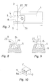
- FIG. 7 is a top view of a tool holder
- FIG. 8 is a cross sectional view along the line D-D of FIG. 7
- FIG. 9 is a cross sectional view of a tool holder
- FIG. 10 is a perspective view of a tool
- FIG. 11 is a perspective view of another tool
- FIG. 12 is a top view of a tool
- FIG. 13 is a side view of a tool
- FIG. 14 is a front view of a tool
- FIG. 15 is a front view of another tool
- FIG. 1 a tool holder 4 with a wedge-shaped recess 8 is shown.
- a tool 2 is to be placed in the recess 8 and fastened by fastening means 20 , which in this example comprise a wedge 24 with a hole 26 and a bolt 28 .
- the bolt 28 is to be engaged with an threaded hole in the bottom of the recess 8 (not shown).
- FIG. 2- 4 a tool 2 is fastened by fastening means 20 in a wedge-shaped recess 8 of a tool holder 4 , which wedge-shape is indicated by an angle A.
- the tool comprises a front side 6 shaped for use in cold forming of metal wire into nails, screws or similar products.
- the tool 2 may be made of a hardened metal alloy.
- an angle A is shown, which angle refers to the wedge-shape of the recess 8 .
- the tool 2 is provided with a similar wedge-shape.
- the fastening means 20 are pressing the tool 2 towards the narrowing end of the recess 8 in order to compress the tool 2 against the recess 8 .
- the fastening means 20 , 24 , 26 , 28 shown in FIGS. 1 - 3 are for a skilled person easily substituted, e.g. with a bolt through the tool holder 4 in the longitudinal direction, pressing directly on the tool 2 , or a hydraulic cylinder built into the holder 4 etc.
- FIG. 5 shows a cross section of a tool 2 placed in a recess 8 in a holder 4 . As displayed, the tool 2 and the recess 8 are fitted closely.
- FIG. 6 shows another cross section in a tool 2 and a tool holder 4 .
- Pressure is exerted on a back side 18 of the tool 2 by a wedge 24 .
- the back side 18 is sloped relative to a bottom 22 of the recess.
- the wedge 24 comprises a shape corresponding to the sloped shape on one side and a shape corresponding to an end side 30 of the recess.
- the end side 30 may be placed at a right angle to the bottom side 22 or at an angle.
- the wedge 24 comprises a through-going hole 26 , through which a bolt 28 may be inserted and engaged with a threaded hole 32 in the holder 4 .
- the tool 2 is placed in a recess 8 , after which the wedge 24 is inserted between the tool 2 and the end side 30 .
- the bolt 28 is inserted and engaged with the threaded hole 32 and tightened. The tightening forces the wedge 24 downwards, whereby a high force is directed on the sloped back side 18 of the tool 2 , said high force compressing the tool forwards against the recess 8 .
- FIG. 7 a tool holder 4 is shown, which holder comprises a wedge-shaped recess 8 with two sides 14 , 16 and an end side 30 .
- a bottom side 22 of the recess is provided with a threaded hole 32 .
- FIG. 8 the cross section D-D from FIG. 7 is shown.
- the two sides 14 and 16 may placed in right angles with a bottom side 22 of a recess 8 .
- the transition between the side 14 and the bottom side 22 respectively the side 16 and the bottom side 22 may be provided with an undercut fillet to reduce local stress levels and to ensure that sufficient space is available for a tool.
- the two sides 14 , 16 may also be placed to form a wedge-shape with an angle Z.
- Said wedge-shape is suited to compress a tool with a force component downwardly against the bottom side 22 .
- both a compression in a plane parallel to the bottom side 22 , as well as in a plane perpendicular to the bottom side 22 may be obtained.
- This provides a tool 2 with built-in compressive stresses, which stresses have to be overcome before a state of tensile stress may appear.
- Tensile stresses which are present from forces exerted on the front side 6 of a tool 2 from using said tool, will be reduced by the built-in compressive stresses. I.e. the magnitude of the tensile stresses actually occurring in the tool 2 are reduced or removed.
- FIG. 10 shows a tool 2 comprising a side 10 and a front side 6 with a concave shaping portion 36 for shaping a nail or screw etc.
- FIG. 11 shows a different or counteracting tool 2 comprising a side 10 and a front side 6 with a shaping portion 36 .
- FIG. 12 shows a tool 2 with a front side 6 comprising a shaping portion 36 , said shaping portion being concave.
- the tool 2 comprises two sides 10 and 12 forming a wedge-shape, in that they are placed in an angle A′.
- the angle A of FIG. 3 and the angle A′ are preferably substantially corresponding.
- FIG. 13 a tool 2 is shown comprising a front side 6 , a side 12 and a sloped back side 18 .
- FIG. 14 shows an embodiment of a tool 2 with sides 10 and 12 , and a front side 6 with a shaping portion 36 .
- FIG. 15 displays another embodiment of a tool 2 with sides 10 and 12 , and a front side 6 with a shaping portion 36 .
- the two sides 10 and 12 are placed under an angle Z′ to form a wedge-shape.
- the angle Z′ is preferably substantially corresponding to the angle Z on FIG. 9.
Landscapes
- Engineering & Computer Science (AREA)
- Mechanical Engineering (AREA)
- Gripping Jigs, Holding Jigs, And Positioning Jigs (AREA)
Abstract
Description
- The present invention relates to a method of fastening a tool in a tool holder, which tool comprises a front side shaped for use in cold forming of metal wire into nails, screws, etc., and which tool holder comprises a recess shaped for receiving the tool. The invention further relates to a tool system comprising a tool and a tool holder, and further to a tool, a tool holder and to a use of a tool and a tool holder.
- Other methods of fastening a tool in a tool holder and devices with such purpose have formerly been employed. In EP 406, 202 A2 a clamping device for making nails is disclosed, where a die (tool) is mounted in a die holder. The die holder is provided with an opening for receiving the die. The back side of the opening is provided with an extension to obtain a slight elasticity, and across said extension a bolt is mounted to clamp the die in the die holder. However, the force from the bolt is relatively small compared to the forces exerted on the die during the nail making process. The tensile stresses in the die are relatively large, and in the die's life span the stresses are applied and relieved in large number of times, such that the well known phenomena of metal fatigue appears. This often leads to cracked dies which have to be replaced, leading to extra costs and lost production output due to lost time.
- The problem is addressed in EP 870,558 A2 and the corresponding U.S. Pat. No. 5,979,216, where the tool insert (die/tool) has been divided in two parts in order to remove harming effects of tensile stresses, i.e. providing a crack in a determined position. The solution is costly, since more parts, which must fit accurately together, have to be made. Also another phenomena known as fretting may appear, which leads to deterioration of the tool inserts anyway. The presence of fretting is caused due to the bolt, which is also employed in this technique, being inadequate to provide sufficient clamping force. With inadequate clamping force, the two parts on each side of the artificial crack are moving slightly away from each other during each loading cycle, and back when the load is removed. The slight movement causes wear and consequently fretting.
- The basic problem has not been solved, namely that the tool insert (die/tool) is subject to too high tensile stresses. When cold forming a wire, the shaping portion of the tool is subject to a high pressure, which pressure is substantially radially directed on the concave shaping portion of the tool. The pressure results in compressive stresses near the surface, where the contact is between the tool and the wire, but slightly further away from the surface, tangentially oriented to the concave shaping portion, tensile stresses prevail. In case of a flat shaping portion, the pressure also results in compressive stresses near the surface, where the contact is between the tool and the wire, and slightly further away from the surface, tangentially oriented to the origin of contact, tensile stresses also prevail.
- One object of the present invention is to provide a method of fastening a tool in a tool holder, such that compressive stresses are initially present in the tool (built-in), when the tool is subjected to the tensile stresses caused by the nail/screw making process, in order to at least reduce the resulting tensile stresses. Another object is to improve the life span of the tool and further to reduce down time in the production.
- The new and inventive aspects of the method according to the invention comprise, that the tool comprises two opposite sides forming a wedge-shape, which are narrowing towards the front side of the tool, and that the recess in the tool holder comprises two corresponding sides, which are placed substantially in the same wedge-shape, and that the tool comprises a back side, and that the tool is fastened by placing the tool in the recess and displacing the tool substantially in the direction of the front side, and compressing the two opposite sides of the tool against the corresponding sides of the recess by applying and maintaining pressure on the back side of the tool with fastening means.
- By the new and inventive aspects it is obtained, that the tool is compressed between the two opposite sides of the recess, such that compressive stresses are introduced in the tool. Due to the wedge-shape of the tool and the recess, the amount of pressure applied to the back side is amplified several times on the sides of the tool, whereby the compressive stresses reach a high level introduced and maintained by the fastening means. When the tool is afterwards used in the nail/screw making process, the tensile stresses caused thereby, must relieve or overcome the compressive stresses before a state of tensile stress in the tool can be present. Hence, the resulting tensile stress level is at least partly reduced, and may be avoided.
- The two opposite sides may further be formed with a wedge-shape relative to a bottom side of the recess, which wedge-shape is narrowing away from said bottom side, and the two corresponding sides in the recess in the tool holder be placed in substantially the same wedge-shape, and the tool be fastened against the bottom side of the recess by applying and maintaining pressure on the back side with fastening means. Hereby a considerable compression may be obtained similarly to the effect obtained as mentioned and explained above, however in a substantially perpendicular direction. Said perpendicular direction is parallel to the direction of another force present in the nail/screw making process, which force is caused when forming the flat head on the nail or screw. Said force introduces shear as well as tensile stresses near and on the surface portion of the tool being in contact with the metal wire. I.e., a prestressed compression will also in this respect reduce the maximum tensile stresses and improve life span of the tool.
- Fastening means may comprise that the back side is sloped relative to the bottom side of the recess, and a wedge is placed with one side against the back side, which wedge comprises a hole, through which hole a bolt is connected to the tool holder, and pressure may be applied and maintained on said back side by tightening the bolt against the wedge. Hereby a way of amplifying the force from the bolt is obtained, which also further amplifies the compression in the tool.
- The new and inventive aspects of the tool system according to the invention comprise that the tool comprises two opposite sides forming a wedge-shape, which is narrowing towards the front side of the tool, and that the recess in the tool holder comprises two corresponding sides, which are placed substantially in the same wedge-shape, and that the tool comprises a back side, which back side is sloped relative to the bottom side of the recess, and that a wedge is placed with one side against the back side and the opposite side against an end side of the recess, which wedge comprises a hole, through which hole a bolt is connected to the tool holder, and that the tool is fastened by tightening the bolt against the wedge.
- Hereby it is obtained, that the tool is compressed between the two opposite sides of the recess, such that compressive stresses are introduced in the tool. Due to the wedge-shape of the two sides, the pressure applied to the back side is amplified several times, whereby the compressive stresses reach a high level. Also the force from the bolt is amplified, whereby the compressive stresses may be further increased. Another advantage is that the tool may be replaced without having to disconnect the tool holder from the machine, since the tool and the fastening means may all be reached from the same and accessible side.
- The two opposite sides may further be formed with a wedge-shape relative to the bottom side of the recess, which wedge-shape is narrowing away from said bottom side, and the two corresponding sides in the recess in the tool holder be placed in substantially the same wedge-shape. Thereby it may be obtained, that harmful effects from the shear as well as tensile stresses near the contact portion of the tool from the making of the nail/screw head may be reduced. A prestressed state of compression will also in this respect reduce the maximum tensile stresses and improve life span of the tool.
- The angle of the wedge-shape narrowing towards the front side of the tool may in a preferred embodiment be between 0.5 and 45 degrees.
- In a more preferred embodiment, the angle may be between 1 and 15 degrees.
- In a further preferred embodiment, the angle of the wedge-shape narrowing away from the bottom side of the recess may be between 1 and 30 degrees.
- The new and inventive aspects of the tool according to the invention comprise, that the tool comprises two opposite sides forming a wedge-shape, which is narrowing towards the front side of the tool, and that the tool is configured for fastening in a tool holder comprising a recess adapted for receiving the tool and fastening means for fastening the tool by application and maintenance of pressure on the tool, in a way such that the two opposite sides may be pre-stressed in the recess. Hereby the tool may be fastened in a tool holder such that tensile stresses in the tool are reduced and increased life span is obtained.
- The new and inventive aspects of the tool holder according to the invention comprise, that the tool holder is adapted for receiving and fastening a wedge-shaped tool for use in cold forming of metal wire into nails, screws, etc., which tool holder comprises a recess shaped for receiving the tool and wherein the tool is to be placed, and that the recess in the tool holder comprises two sides forming a wedge-shape, which is narrowing towards an open end of the recess, and that the tool holder comprises fastening means configured for fastening the tool by application and maintenance of pressure on the tool, in a way such that the tool may be pre-stressed in the recess against the sides. Hereby it is obtained, that the tool holder may receive and fasten a tool, in a way such that the life span of the tool is increased.
- The new and inventive aspects of the use of the tool and tool holder according to the invention comprise, that these are used in a machine or plant in a process for the manufacture of nails, screws and similar items, whereby lost production time is decreased.
- In the following the invention is further explained with the use of drawings, where examples of embodiments are shown.
- FIG. 1 is an exploded view of a tool system
- FIG. 2 is a perspective view of a tool system
- FIG. 3 is a top view of a tool system
- FIG. 4 is a front view of a tool system
- FIG. 5 is a cross sectional view along the line C-C of FIG. 3
- FIG. 6 is a cross sectional view along the line B-B of FIG. 4
- FIG. 7 is a top view of a tool holder
- FIG. 8 is a cross sectional view along the line D-D of FIG. 7
- FIG. 9 is a cross sectional view of a tool holder
- FIG. 10 is a perspective view of a tool
- FIG. 11 is a perspective view of another tool
- FIG. 12 is a top view of a tool
- FIG. 13 is a side view of a tool
- FIG. 14 is a front view of a tool
- FIG. 15 is a front view of another tool
- In FIG. 1 a
tool holder 4 with a wedge-shapedrecess 8 is shown. Atool 2 is to be placed in therecess 8 and fastened by fastening means 20, which in this example comprise awedge 24 with ahole 26 and abolt 28. Thebolt 28 is to be engaged with an threaded hole in the bottom of the recess 8 (not shown). - In FIG. 2- 4 a
tool 2 is fastened by fastening means 20 in a wedge-shapedrecess 8 of atool holder 4, which wedge-shape is indicated by an angle A. - The tool comprises a
front side 6 shaped for use in cold forming of metal wire into nails, screws or similar products. Thetool 2 may be made of a hardened metal alloy. In FIG. 3 an angle A is shown, which angle refers to the wedge-shape of therecess 8. Preferably, thetool 2 is provided with a similar wedge-shape. The fastening means 20 are pressing thetool 2 towards the narrowing end of therecess 8 in order to compress thetool 2 against therecess 8. The fastening means 20, 24, 26, 28 shown in FIGS. 1-3 are for a skilled person easily substituted, e.g. with a bolt through thetool holder 4 in the longitudinal direction, pressing directly on thetool 2, or a hydraulic cylinder built into theholder 4 etc. - FIG. 5 shows a cross section of a
tool 2 placed in arecess 8 in aholder 4. As displayed, thetool 2 and therecess 8 are fitted closely. - FIG. 6 shows another cross section in a
tool 2 and atool holder 4. Pressure is exerted on aback side 18 of thetool 2 by awedge 24. Theback side 18 is sloped relative to a bottom 22 of the recess. Thewedge 24 comprises a shape corresponding to the sloped shape on one side and a shape corresponding to anend side 30 of the recess. Theend side 30 may be placed at a right angle to thebottom side 22 or at an angle. Thewedge 24 comprises a through-goinghole 26, through which abolt 28 may be inserted and engaged with a threadedhole 32 in theholder 4. At first thetool 2 is placed in arecess 8, after which thewedge 24 is inserted between thetool 2 and theend side 30. Afterwards, thebolt 28 is inserted and engaged with the threadedhole 32 and tightened. The tightening forces thewedge 24 downwards, whereby a high force is directed on the sloped backside 18 of thetool 2, said high force compressing the tool forwards against therecess 8. - In FIG. 7 a
tool holder 4 is shown, which holder comprises a wedge-shapedrecess 8 with twosides end side 30. Abottom side 22 of the recess is provided with a threadedhole 32. - In FIG. 8 the cross section D-D from FIG. 7 is shown. The two
sides bottom side 22 of arecess 8. The transition between theside 14 and thebottom side 22 respectively theside 16 and thebottom side 22 may be provided with an undercut fillet to reduce local stress levels and to ensure that sufficient space is available for a tool. - In FIG. 9 it is shown that the two
sides bottom side 22. In that way, both a compression in a plane parallel to thebottom side 22, as well as in a plane perpendicular to thebottom side 22, may be obtained. This provides atool 2 with built-in compressive stresses, which stresses have to be overcome before a state of tensile stress may appear. Tensile stresses, which are present from forces exerted on thefront side 6 of atool 2 from using said tool, will be reduced by the built-in compressive stresses. I.e. the magnitude of the tensile stresses actually occurring in thetool 2 are reduced or removed. - FIG. 10 shows a
tool 2 comprising aside 10 and afront side 6 with aconcave shaping portion 36 for shaping a nail or screw etc. - FIG. 11 shows a different or counteracting
tool 2 comprising aside 10 and afront side 6 with a shapingportion 36. - FIG. 12 shows a
tool 2 with afront side 6 comprising a shapingportion 36, said shaping portion being concave. Thetool 2 comprises twosides - In FIG. 13 a
tool 2 is shown comprising afront side 6, aside 12 and a sloped backside 18. - FIG. 14 shows an embodiment of a
tool 2 withsides front side 6 with a shapingportion 36. - FIG. 15 displays another embodiment of a
tool 2 withsides front side 6 with a shapingportion 36. The twosides
Claims (11)
Priority Applications (1)
| Application Number | Priority Date | Filing Date | Title |
|---|---|---|---|
| US10/123,229 US6786828B2 (en) | 2002-04-17 | 2002-04-17 | Method of fastening a tool in a tool holder |
Applications Claiming Priority (1)
| Application Number | Priority Date | Filing Date | Title |
|---|---|---|---|
| US10/123,229 US6786828B2 (en) | 2002-04-17 | 2002-04-17 | Method of fastening a tool in a tool holder |
Publications (2)
| Publication Number | Publication Date |
|---|---|
| US20030196473A1 true US20030196473A1 (en) | 2003-10-23 |
| US6786828B2 US6786828B2 (en) | 2004-09-07 |
Family
ID=29214467
Family Applications (1)
| Application Number | Title | Priority Date | Filing Date |
|---|---|---|---|
| US10/123,229 Expired - Lifetime US6786828B2 (en) | 2002-04-17 | 2002-04-17 | Method of fastening a tool in a tool holder |
Country Status (1)
| Country | Link |
|---|---|
| US (1) | US6786828B2 (en) |
Cited By (2)
| Publication number | Priority date | Publication date | Assignee | Title |
|---|---|---|---|---|
| US20050188741A1 (en) * | 2004-02-27 | 2005-09-01 | Forrester Gregory P. | Nail manufacturing tool holder having a quick change mechanism |
| WO2009052538A1 (en) * | 2007-10-22 | 2009-04-30 | Ceratizit Austria Gesellschaft M.B.H. | Tool for clamping or cutting to length, and clamping jaw or cutting body |
Families Citing this family (4)
| Publication number | Priority date | Publication date | Assignee | Title |
|---|---|---|---|---|
| WO2002072294A1 (en) * | 2001-03-08 | 2002-09-19 | Honda Giken Kogyo Kabushiki Kaisha | Device and method for press forming |
| US6780116B2 (en) * | 2001-08-13 | 2004-08-24 | Kennametal Inc. | Wear resistant nail manufacturing tool inserts |
| JP5987784B2 (en) * | 2013-05-29 | 2016-09-07 | トヨタ紡織株式会社 | Press mold |
| US11413679B2 (en) * | 2019-09-05 | 2022-08-16 | Enkotec A/S | Long-life die for the manufacturing of elongate bodies |
Citations (6)
| Publication number | Priority date | Publication date | Assignee | Title |
|---|---|---|---|---|
| US2178711A (en) * | 1938-08-25 | 1939-11-07 | Werner Ignacy | Die holder for nail making dies |
| US3965716A (en) * | 1974-10-15 | 1976-06-29 | Toyota Jidosha Kogyo Kabushiki Kaisha | Device for swage-forging shafts |
| US5014540A (en) * | 1990-03-28 | 1991-05-14 | Pat Ferrante | Jig assembly |
| US5979216A (en) * | 1997-04-09 | 1999-11-09 | Schwartzkopf Technologies, Corp. | Wear resistant tool insert |
| US6110047A (en) * | 1999-08-16 | 2000-08-29 | Lin; Tsang-Yao | Mold for forming a screw with an auger tip |
| US20030032489A1 (en) * | 2001-08-13 | 2003-02-13 | Hurst Joe L. | Wear resistant nail manufacturing tool inserts |
Family Cites Families (4)
| Publication number | Priority date | Publication date | Assignee | Title |
|---|---|---|---|---|
| US1578351A (en) * | 1925-03-24 | 1926-03-30 | Frank H Nullmeyer | Die holder for wire-drawing blocks |
| US4520701A (en) * | 1982-12-27 | 1985-06-04 | Watamura Abe S | Tool holder for lathe |
| SE467530B (en) | 1989-06-30 | 1992-08-03 | Haamex Haardmetallverktyg Ab | CLAUM BACK FOR SPIKE MANUFACTURING |
| DE69802862T2 (en) | 1997-05-06 | 2002-08-29 | Slagteriernes Forskningsinstitut, Roskilde | Method and device for gutting carcasses |
-
2002
- 2002-04-17 US US10/123,229 patent/US6786828B2/en not_active Expired - Lifetime
Patent Citations (6)
| Publication number | Priority date | Publication date | Assignee | Title |
|---|---|---|---|---|
| US2178711A (en) * | 1938-08-25 | 1939-11-07 | Werner Ignacy | Die holder for nail making dies |
| US3965716A (en) * | 1974-10-15 | 1976-06-29 | Toyota Jidosha Kogyo Kabushiki Kaisha | Device for swage-forging shafts |
| US5014540A (en) * | 1990-03-28 | 1991-05-14 | Pat Ferrante | Jig assembly |
| US5979216A (en) * | 1997-04-09 | 1999-11-09 | Schwartzkopf Technologies, Corp. | Wear resistant tool insert |
| US6110047A (en) * | 1999-08-16 | 2000-08-29 | Lin; Tsang-Yao | Mold for forming a screw with an auger tip |
| US20030032489A1 (en) * | 2001-08-13 | 2003-02-13 | Hurst Joe L. | Wear resistant nail manufacturing tool inserts |
Cited By (3)
| Publication number | Priority date | Publication date | Assignee | Title |
|---|---|---|---|---|
| US20050188741A1 (en) * | 2004-02-27 | 2005-09-01 | Forrester Gregory P. | Nail manufacturing tool holder having a quick change mechanism |
| US7090585B2 (en) | 2004-02-27 | 2006-08-15 | Kennametal Inc. | Nail manufacturing tool holder having a quick change mechanism |
| WO2009052538A1 (en) * | 2007-10-22 | 2009-04-30 | Ceratizit Austria Gesellschaft M.B.H. | Tool for clamping or cutting to length, and clamping jaw or cutting body |
Also Published As
| Publication number | Publication date |
|---|---|
| US6786828B2 (en) | 2004-09-07 |
Similar Documents
| Publication | Publication Date | Title |
|---|---|---|
| US4689984A (en) | Method for producing male conical threads | |
| US5011351A (en) | Wedge lock die washer | |
| US6786828B2 (en) | Method of fastening a tool in a tool holder | |
| CN113195937B (en) | Fasteners for cable conveyor belts | |
| Makinouchi et al. | A finite element analysis of flattening of surface asperities by perfectly lubricated rigid dies in metal working processes | |
| US20020158099A1 (en) | Connecting rod breaking and dividing device | |
| EP0351111A1 (en) | Method of making threaded fasteners | |
| CA2524636C (en) | Inhibiting metal fatigue in a tool secured in a tool holder | |
| JPH10175018A (en) | Die matching straightening jig and die matching straightening method for segmental die | |
| RU2328358C2 (en) | Method and device for desembarkation of metal core ends | |
| CN216027326U (en) | Supplementary preflex frock of type of falling T rib | |
| CN101244447A (en) | Method for assembling at least two elements by means of a crimping rivet | |
| KR20110112563A (en) | Pipe crimp fastener | |
| JP3726508B2 (en) | Easy separation of connecting rod split bearing cap | |
| EP0891449B1 (en) | Method for the production of a prestressed plate-shaped building component | |
| CN217466205U (en) | Riveting clamp with height limiting block | |
| CN212615833U (en) | Fixed firm pressure rivet nut | |
| US7900657B2 (en) | Jaw for sealless strapping machine | |
| CN217122947U (en) | High compatible anchor clamps of curved surface work piece | |
| CN2319434Y (en) | Switch rail straightening appts. | |
| JP3025650U (en) | Bottom screwed structure of hydraulic compressor | |
| CN113305605B (en) | Wedge-type positioning fixture and positioning method | |
| US6370933B1 (en) | Die and method for reducing controlling the formation of flash on parts | |
| CN201940820U (en) | Fixture | |
| CN107791961B (en) | Rebound-resistant roof rack model and manufacturing process thereof |
Legal Events
| Date | Code | Title | Description |
|---|---|---|---|
| AS | Assignment |
Owner name: ENKOTEC A/S, DENMARK Free format text: ASSIGNMENT OF ASSIGNORS INTEREST;ASSIGNOR:SORENSEN, SVEND-HELGE SELL;REEL/FRAME:015665/0066 Effective date: 20040628 |
|
| STCF | Information on status: patent grant |
Free format text: PATENTED CASE |
|
| FEPP | Fee payment procedure |
Free format text: PAYOR NUMBER ASSIGNED (ORIGINAL EVENT CODE: ASPN); ENTITY STATUS OF PATENT OWNER: SMALL ENTITY Free format text: PAYER NUMBER DE-ASSIGNED (ORIGINAL EVENT CODE: RMPN); ENTITY STATUS OF PATENT OWNER: SMALL ENTITY |
|
| FPAY | Fee payment |
Year of fee payment: 4 |
|
| FEPP | Fee payment procedure |
Free format text: PAYOR NUMBER ASSIGNED (ORIGINAL EVENT CODE: ASPN); ENTITY STATUS OF PATENT OWNER: SMALL ENTITY Free format text: PAYER NUMBER DE-ASSIGNED (ORIGINAL EVENT CODE: RMPN); ENTITY STATUS OF PATENT OWNER: SMALL ENTITY |
|
| FPAY | Fee payment |
Year of fee payment: 8 |
|
| FPAY | Fee payment |
Year of fee payment: 12 |