US20030194466A1 - System and method for molding plastic gear suppressing shrinkage - Google Patents
System and method for molding plastic gear suppressing shrinkage Download PDFInfo
- Publication number
- US20030194466A1 US20030194466A1 US10/430,208 US43020803A US2003194466A1 US 20030194466 A1 US20030194466 A1 US 20030194466A1 US 43020803 A US43020803 A US 43020803A US 2003194466 A1 US2003194466 A1 US 2003194466A1
- Authority
- US
- United States
- Prior art keywords
- gear
- mold
- prescribed number
- prescribed
- plastic
- Prior art date
- Legal status (The legal status is an assumption and is not a legal conclusion. Google has not performed a legal analysis and makes no representation as to the accuracy of the status listed.)
- Granted
Links
- 239000004033 plastic Substances 0.000 title claims abstract description 125
- 238000000465 moulding Methods 0.000 title claims abstract description 29
- 238000000034 method Methods 0.000 title claims abstract description 16
- 238000005520 cutting process Methods 0.000 claims description 9
- 230000008859 change Effects 0.000 description 22
- 230000005540 biological transmission Effects 0.000 description 13
- 238000012546 transfer Methods 0.000 description 13
- 230000008569 process Effects 0.000 description 7
- 230000008901 benefit Effects 0.000 description 4
- 230000004048 modification Effects 0.000 description 4
- 238000012986 modification Methods 0.000 description 4
- 238000012360 testing method Methods 0.000 description 3
- 238000002347 injection Methods 0.000 description 2
- 239000007924 injection Substances 0.000 description 2
- 238000001746 injection moulding Methods 0.000 description 2
- 239000002184 metal Substances 0.000 description 2
- 238000012545 processing Methods 0.000 description 2
- 238000004140 cleaning Methods 0.000 description 1
- 238000001816 cooling Methods 0.000 description 1
- 230000003247 decreasing effect Effects 0.000 description 1
- 230000000694 effects Effects 0.000 description 1
- 230000005684 electric field Effects 0.000 description 1
- 238000007373 indentation Methods 0.000 description 1
- 238000004519 manufacturing process Methods 0.000 description 1
- 239000007769 metal material Substances 0.000 description 1
- 239000002991 molded plastic Substances 0.000 description 1
- 238000010137 moulding (plastic) Methods 0.000 description 1
- 230000003287 optical effect Effects 0.000 description 1
- 230000002093 peripheral effect Effects 0.000 description 1
- 102200082816 rs34868397 Human genes 0.000 description 1
- 238000000926 separation method Methods 0.000 description 1
- 238000010008 shearing Methods 0.000 description 1
Images


Classifications
-
- B—PERFORMING OPERATIONS; TRANSPORTING
- B29—WORKING OF PLASTICS; WORKING OF SUBSTANCES IN A PLASTIC STATE IN GENERAL
- B29C—SHAPING OR JOINING OF PLASTICS; SHAPING OF MATERIAL IN A PLASTIC STATE, NOT OTHERWISE PROVIDED FOR; AFTER-TREATMENT OF THE SHAPED PRODUCTS, e.g. REPAIRING
- B29C45/00—Injection moulding, i.e. forcing the required volume of moulding material through a nozzle into a closed mould; Apparatus therefor
- B29C45/0025—Preventing defects on the moulded article, e.g. weld lines, shrinkage marks
-
- F—MECHANICAL ENGINEERING; LIGHTING; HEATING; WEAPONS; BLASTING
- F16—ENGINEERING ELEMENTS AND UNITS; GENERAL MEASURES FOR PRODUCING AND MAINTAINING EFFECTIVE FUNCTIONING OF MACHINES OR INSTALLATIONS; THERMAL INSULATION IN GENERAL
- F16H—GEARING
- F16H55/00—Elements with teeth or friction surfaces for conveying motion; Worms, pulleys or sheaves for gearing mechanisms
- F16H55/02—Toothed members; Worms
- F16H55/17—Toothed wheels
-
- G—PHYSICS
- G03—PHOTOGRAPHY; CINEMATOGRAPHY; ANALOGOUS TECHNIQUES USING WAVES OTHER THAN OPTICAL WAVES; ELECTROGRAPHY; HOLOGRAPHY
- G03G—ELECTROGRAPHY; ELECTROPHOTOGRAPHY; MAGNETOGRAPHY
- G03G15/00—Apparatus for electrographic processes using a charge pattern
- G03G15/75—Details relating to xerographic drum, band or plate, e.g. replacing, testing
- G03G15/757—Drive mechanisms for photosensitive medium, e.g. gears
-
- B—PERFORMING OPERATIONS; TRANSPORTING
- B29—WORKING OF PLASTICS; WORKING OF SUBSTANCES IN A PLASTIC STATE IN GENERAL
- B29C—SHAPING OR JOINING OF PLASTICS; SHAPING OF MATERIAL IN A PLASTIC STATE, NOT OTHERWISE PROVIDED FOR; AFTER-TREATMENT OF THE SHAPED PRODUCTS, e.g. REPAIRING
- B29C45/00—Injection moulding, i.e. forcing the required volume of moulding material through a nozzle into a closed mould; Apparatus therefor
- B29C45/17—Component parts, details or accessories; Auxiliary operations
- B29C45/40—Removing or ejecting moulded articles
- B29C2045/4063—Removing or ejecting moulded articles preventing damage to articles caused by the ejector
-
- B—PERFORMING OPERATIONS; TRANSPORTING
- B29—WORKING OF PLASTICS; WORKING OF SUBSTANCES IN A PLASTIC STATE IN GENERAL
- B29C—SHAPING OR JOINING OF PLASTICS; SHAPING OF MATERIAL IN A PLASTIC STATE, NOT OTHERWISE PROVIDED FOR; AFTER-TREATMENT OF THE SHAPED PRODUCTS, e.g. REPAIRING
- B29C45/00—Injection moulding, i.e. forcing the required volume of moulding material through a nozzle into a closed mould; Apparatus therefor
- B29C45/17—Component parts, details or accessories; Auxiliary operations
- B29C45/40—Removing or ejecting moulded articles
-
- B—PERFORMING OPERATIONS; TRANSPORTING
- B29—WORKING OF PLASTICS; WORKING OF SUBSTANCES IN A PLASTIC STATE IN GENERAL
- B29L—INDEXING SCHEME ASSOCIATED WITH SUBCLASS B29C, RELATING TO PARTICULAR ARTICLES
- B29L2015/00—Gear wheels or similar articles with grooves or projections, e.g. control knobs
- B29L2015/003—Gears
-
- F—MECHANICAL ENGINEERING; LIGHTING; HEATING; WEAPONS; BLASTING
- F16—ENGINEERING ELEMENTS AND UNITS; GENERAL MEASURES FOR PRODUCING AND MAINTAINING EFFECTIVE FUNCTIONING OF MACHINES OR INSTALLATIONS; THERMAL INSULATION IN GENERAL
- F16H—GEARING
- F16H55/00—Elements with teeth or friction surfaces for conveying motion; Worms, pulleys or sheaves for gearing mechanisms
- F16H55/02—Toothed members; Worms
- F16H55/06—Use of materials; Use of treatments of toothed members or worms to affect their intrinsic material properties
- F16H2055/065—Moulded gears, e.g. inserts therefor
-
- Y—GENERAL TAGGING OF NEW TECHNOLOGICAL DEVELOPMENTS; GENERAL TAGGING OF CROSS-SECTIONAL TECHNOLOGIES SPANNING OVER SEVERAL SECTIONS OF THE IPC; TECHNICAL SUBJECTS COVERED BY FORMER USPC CROSS-REFERENCE ART COLLECTIONS [XRACs] AND DIGESTS
- Y10—TECHNICAL SUBJECTS COVERED BY FORMER USPC
- Y10T—TECHNICAL SUBJECTS COVERED BY FORMER US CLASSIFICATION
- Y10T29/00—Metal working
- Y10T29/49—Method of mechanical manufacture
- Y10T29/49462—Gear making
- Y10T29/49467—Gear shaping
- Y10T29/49476—Gear tooth cutting
Definitions
- This invention relates to a plastic gear molding system and method, in particular relates to a plastic gear molding system and method capable of preventing from partial shrinkage during its molding process.
- a transmission apparatus It is well known in a transmission apparatus to have at least one plastic gear that transmits a rotation force of a driving motor to a driven member.
- a rotation force of a driving motor is generally transmitted to an image carrier through a driven member contacting the surface of the image carrier or the like for forming a toner image on the surface of the image carrier during its rotation.
- the conventional plastic gear may also be used in a duplicator, a camera, a video deck and a compact disk player and so on to transmit a rotational force to a driven member thereof.
- a plurality of ribs may be symmetrically integrally mounted on both front and rear surfaces of the web in a manner such that each one edge connects with the hub and each another edge connects to the gear ring.
- a diameter of such a plastic gear generally varies during its molding process due to the so called a shrink phenomenon of the plastic.
- a peripheral speed of the plastic gear periodically changes when it rotates, and accordingly unevenness of the rotational speed of the driven member may arise.
- a background plastic gear 14 includes a cylindrical hub 25 disposed as a core portion thereof and is supported by the shaft 15 illustrated in FIG. 2.
- the plastic gear 14 further includes a gear ring 27 having substantially concentric with the hub 24 and having a larger diameter than the hub 24 , which is disposed at of the hub 25 .
- the gear ring 27 includes a plurality of gear teeth 26 on an outer circumferential surface thereof.
- the plastic gear 14 further includes a web 28 constituted by a circular plate whose ends integrally connect the hub 24 and the gear ring 27 .
- a plurality of ribs 28 A and 28 B are each integrally formed respectively on front and rear sides of the web 28 .
- Each of the plurality of groups of the ribs extends in a radial state from the hub 24 to the gear ring 27 .
- the ribs 29 A formed on a front surface of the web 28 are arranged at a prescribed angular interval around the hub 25 .
- the ribs 29 B formed on a rear surface of the web 28 are arranged in a same way as the ribs 29 A.
- Each of the ribs 29 A and 29 B is symmetrically disposed at both the front and rear surfaces of the web 28 .
- a perpendicular cross section of the web 28 intersects the cross sections of both the ribs 29 A and 29 B as illustrated in FIG. 7.
- a possible cause of the change in rotational speed of the plastic gear is explained below.
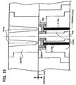
- a portion of the gear ring 27 and gear teeth 26 A, 26 B and 26 C each mounted on the circumference of the gear ring 27 are typically illustrated in FIG. 15.
- ends of the ribs 29 A and 29 B are connected to the same portion (shown enlarged for ease of illustration) of the gear ring 27 between the tooth 26 B and 26 C.
- a space between the teeth 26 B and 26 C is illustrated larger than actual for an explaining purpose.
- the portion of the gear ring 27 between the teeth 26 B and 26 C is more indented toward a rotational center of the plastic gear than other portions thereof, since the partial shrink occurs when the plastic gear is molded.
- the tooth 29 A positioning at a left side of the ribs 29 A and 29 B inclines on the right and the tooth 29 B positioning at a right side of the ribs 29 A and 29 B inclines to the left as illustrated in FIG. 15.
- a gear 26 D meshes with the plastic gear 14 as illustrated in FIG. 15. If a pressure angle at a gear connecting portion at which a gear tooth 26 D of another gear meshes with the gear tooth 26 A is ⁇ 0 , a pressure angle ⁇ 1 , of the gear tooth 26 B inclining to the right is larger than ⁇ 0 , A pressure angle ⁇ 2 of the gear tooth 26 C inclining on the left is smaller than ⁇ 0 .
- angular velocities are ⁇ 0 , ⁇ 1 , and ⁇ 2 correspond to gear portions having the angles of ⁇ 0 , ⁇ 1 , and ⁇ 2 .
- a rotational speed of the conventional driving motor 10 generally varies once per one revolution thereof.
- a rotational velocity of the PC drum 1 remarkably changes at a prescribed timing, if a frequency of a change in rotational speed of the conventional driving motor 10 is substantially coincident with that of the plastic gear 14 .
- unevenness of a toner image arises on the surface of the PC drum 1 , and the image quality is inferior.
- a frequency of a change in rotational speed is 30 Hz (obtained by dividing 1,800 rpm by 60 seconds). If the number of teeth of the output gear 13 of the driving motor 10 is ten, a number of teeth of a plastic gear 14 that meshes with the output gear is seventy, and a number of ribs 28 A and 28 B mounted on each of the surfaces of the web 28 of the plastic gear 14 is seven, a frequency of a change in rotational speed of the gear 14 becomes 30 Hz, as is obtained by the following formula.
- a plastic gear may be produced using an injection molding method.
- the mold is required to be remodeled to produce a different number of the ribs.
- it generally is expensive to remodel the mold that has produced the previous model of the plastic gear for example, by changing a plastic injection gate, through which molten plastic is poured.
- the prescribed number of ejecting pins is inserted into guiding holes provided in a core respectively.
- the gate and cavity are separated from the core as illustrated in FIG. 20, and the prescribed number of ejecting pins then automatically push the plastic gear out to eject the plastic gear from the core.
- each of the plurality of ejecting pins is preferably arranged to contact the plastic gear with it leading end as being as close to the gear bottom as possible, as illustrated in FIG. 22, in order to minimize shearing force to be generated between the pressure and the resistance in the plastic gear as much as possible.
- a prescribed plurality of portions of the section of the gear bottom generally are molded to be fat, as illustrated in FIGS. 23A and 23B, and the plurality of ejecting pins contacts the fat sections directly or via a prescribed base plate.
- an object of the present invention is to address and resolve the above identified and other problems.
- Another object of the present invention is to provide a new plastic gear molding system including a mold having a prescribed gear shape and a gear bottom of constant thickness, and a cutting device for cutting a prescribed number of substantially radial grooves in the mold.
- a prescribed number of gates may be provided for pouring molten plastic into the mold.
- a prescribed number of pins having a diameter smaller than the thickness of the gear bottom may be provided for ejecting the gear from the mold.
- the prescribed number of pins may have substantially the same diameter and said prescribed number is determined as is in a reverse ratio to duplication of the radius of each of the pins.
- FIG. 1 is a schematic sectional view illustrating an image forming apparatus to which a plastic gear of one embodiment of the present invention is to be applied;
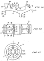
- FIG. 2 is a plan view, including a partial cross sectional view, illustrating a transmission device of the image forming apparatus illustrated in FIG. 1, which employs a plastic gear;
- FIG. 3 is a front side view illustrating the transmission device illustrated in FIG. 2;
- FIG. 4 is a perspective view illustrating one example of a plastic gear to be used in the transmission device illustrated in FIG. 3;
- FIG. 5 is a vertical cross sectional view illustrating the plastic gear illustrated in FIG. 4;
- FIG. 6 is a front side view illustrating the plastic gear when viewed from a direction shown by an arrow A illustrated in FIG. 5;
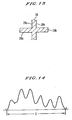
- FIG. 7 is a front side view illustrating the plastic gear when viewed from a direction shown by an arrow B illustrated in FIG. 5;
- FIG. 8 is a cross sectional view illustrating a positional relation between a first rib formed on a front surface and a second rib formed on a rear surface of a web of the plastic gear illustrated in FIGS. 4 through 7;
- FIG. 9 is a graph showing a result of a meshing test executed using an eccentric condition of a plastic gear of the present invention during one revolution thereof;
- FIG. 10 is a vertical cross sectional view illustrating a plastic gear having a plurality of ribs symmetrically formed on front and rear surfaces of a web of a conventional plastic gear;
- FIG. 11 is a front side view illustrating the conventional plastic gear when viewed from a direction shown by an arrow Al as illustrated in FIG. 10;
- FIG. 12 is a rear side view illustrating the conventional plastic gear when viewed from a direction shown by an arrow B 1 as illustrated in FIG. 10;
- FIG. 13 is a cross sectional view that illustrates a positional relation between a first rib formed on the front surface and a second rib formed on the rear surface of a web of the conventional plastic gear illustrated in FIGS. 10 through 12;
- FIG. 14 is a graph showing a result of a meshing test executed using an eccentric condition of the conventional plastic gear during one revolution thereof;
- FIG. 15 is a partial cross sectional view illustrating the conventional plastic gear, which explains a problem of the conventional plastic gear
- FIG. 16 is a cross sectional view illustrating another embodiment of a plastic gear of the present invention, which has a rib having a different height along a length thereof;
- FIG. 17 is a chart illustrating a relation between a gate of a mold, through which molten plastic is poured into an inside of the mold, and a plastic gear to be molded;
- FIG. 18 is a cross sectional view illustrating one examples of molds used in the present invention.
- FIG. 19 is a cross sectional view illustrating a background mold gear ejecting process using an ejecting pin
- FIG. 20A is a cross sectional view illustrating the background mold separating process when a gate is separated from the gear
- FIG. 20B is a cross sectional view illustrating the background mold separating process when both of the gate and a cavity are separated from the gear;
- FIG. 21 is a cross sectional view illustrating the background mold separating process when the gear is separated from the mold
- FIG. 22 is cross sectional views illustrating relations between pressure applied by the ejecting pin and resistance produced during the separation of the gear along the gear teeth;
- FIG. 23A is a martial sectional view illustrating a gear bottom having plurality of fat sections for engaging with leading ends of the ejecting pins, respectively;
- FIG. 23B is a schematic perspective view of the bottom illustrated in FIG. 23A;
- FIG. 23C is a sectional view illustrating the background molding system when a gear having the gear bottom illustrated in FIGS. 23A and 23B is molded and ejected;
- FIG. 24A is a graph showing unevenness of the rotational speed of the conventional plastic gear
- FIG. 24B is a graph showing improved unevenness of the rotational speed of the plastic gear according to the present invention.
- FIG. 25A is a schematic cross-sectional view of the molding system according to the present invention.
- FIG. 25B is a schematic cross-sectional view of the gear bottom of the plastic gear molded in the molding system illustrated in FIG. 25A.
- FIG. 1 An image forming apparatus to which a plastic gear of the present invention is to be applied is illustrated in FIG. 1.
- a laser printer is illustrated in FIG. 1 as one of example of the image forming apparatus.
- the laser printer includes a photo-conductive drum 1 (hereinafter referred to as a PC drum 1 ) supported by a frame of the laser printer body to freely rotate, which is driven in a clockwise direction by a transmission device explained later in detail.
- a discharge roller 2 is disposed in contact with a surface of the PC drum 1 , which rotates counter clockwise and applies a charge having a prescribed polarity to the surface thereof.
- An optical writing device 3 is provided so as to generate a laser light beam L.
- the laser light beam is then optically modulated and then radiated to the surface of the PC drum 1 , thereby forming a prescribed latent image thereon.
- a developing apparatus 4 is provided so as to develop the latent image when it passes through the developing station.
- a sheet cassette accommodates a plurality of printing sheets P.
- the printing sheet P fed from the cassette is transferred to a transfer station 6 to receive a toner image at the position.
- a transfer belt 7 disposed below the PC drum 1 in pressure contact with the surface of the PC drum 1 at the transfer position.
- the transfer belt 7 is rotated in a predetermined direction.
- An electric field is created between the transfer belt and the PC drum 1 at the transfer position so that a transfer bias voltage that renders enables toner transfer is applied therebetween.
- the toner image on the surface of the PC drum 1 is transferred onto the printing sheet due to the bias voltage.
- a fixing device not shown, is provided downstream of the transfer station.
- the toner on the printing sheet P is permanently fixed on the printing sheet P by the fixing device when it passes through the same.
- the printing sheet P is then ejected to the outside of the image forming apparatus and stacked on a sheet receiving tray, not shown.
- a cleaning device 8 is employed so as to clean the surface of the PC drum 1 by removing a residual toner remaining on the surface thereof after the toner transfer is completed.
- a discharge lamp may be provided so as to discharge the surface using a light beam.
- FIG. 2 One example of combinations of a driving motor 10 and a transmission device that transmits a rotational force from the driving motor 10 to the driven member is illustrated in partial sectional plan view in FIG. 2, and in a front view in FIG. 3.
- the driving motor 10 is fixedly supported on a bracket 12 secured by the frame 11 .
- An output gear 13 is connected to an output shaft of the driving motor 10 , with which meshes with a first gear 14 made of plastic.
- the first gear 14 is supported by a shaft 15 to freely rotate therearound, which is secured by the bracket 12 .
- the first gear 14 meshes with a second gear 16 made of plastic.
- the second gear 16 is secured to a shaft 17 rotatably supported by the bracket 12 through a bearing.
- a timing pulley 18 concentric with the second gear 16 is secured to one end of the shaft 17 .
- Another timing pulley 19 is secured to a supporting shaft that secures and supports the PC drum 1 therearound.
- An endless timing belt 21 is wound around both the timing pulleys 18 and 19 .
- the PC drum 1 , the supporting shaft 22 and the timing pulley 19 are all concentric.
- An edge portion of the supporting shaft 22 is rotatably supported by a PC drum holder 24 that is secured to the frame 11 of the laser printer body.
- the frame 11 also rotatably supports another edge portion, not shown, of the supporting shaft 22 .
- the output gear 13 may be made of a metal based upon standard S45C. Both the first and the second gear 14 and 16 may be molded articles made of plastic as mentioned earlier.
- the PC drum 1 may be a driven member that is driven by the driving motor through the gears 14 and 16 .
- the transmission device may have one or more plastic gears.
- the typical plastic gear 14 is hereinafter explained.
- the plastic gear 14 includes a cylindrical hub 25 disposed as a core portion and supported by the shaft 15 as illustrated in FIG. 2.
- the plastic gear 14 further includes an external gear ring 27 which is substantially concentric with the hub 24 , has a larger diameter than the hub 24 and is disposed outside of the hub 25 .
- the gear ring 27 includes a plurality of gear teeth 26 on its outer circumferential surface.
- the plastic gear 14 further includes a web 28 constituted by a circular plate whose edges integrally connect the hub 24 with the gear ring 27 .
- An injection type plastic molding device may used to mold the plastic gear 14 using plastic.
- a plurality of ribs 28 A and 28 B are integrally formed respectively on front and rear sides of the web 28 .
- a constitution of the plurality of ribs 28 A and 28 B are explained later in detail.
- the second gear is molded in the same manner as mentioned above.
- each of rib groups 29 A and 29 B is formed on the sides of the web 28 in a manner such that each rib extends radially from the hub 25 toward the gear ring 27 at a prescribed angular interval around the hub 25 .
- Each of the ribs 29 A is angularly shifted from each of the ribs 29 B arranged on the back side of the web 28 .
- ribs 29 A and 29 B are not symmetrically disposed on the side surfaces of the plastic gear 14 .
- FIGS. 4 through 7 show six ribs are formed each of the side surfaces of the web 28 of the plastic gear 14 .
- Each of the angular spacings ⁇ 1 , of the ribs 29 A and 29 B is therefore 60° (obtained by dividing 360 degrees by 6).
- Each of the ribs 29 B formed on the rear side of the web 28 is located at a position that corresponds to a middle angular position between neighboring ribs 29 A formed on the front side of the web 28 .
- each of the ribs 29 A is shifted by 30 degrees ( ⁇ 2 ) from each of the ribs 29 B.
- the number of ribs 29 A and 29 B can be optionally determined.
- At least one rib can be utilized on a surface of a web 28 for a purpose of increasing a rigidity of a plastic gear 14 . If twelve ribs are employed, ⁇ 1 , has 30 degrees and ⁇ 2 has 15 degrees.
- the section through the web 28 does not intersects the sections of both the ribs 29 A and 29 B, since the ribs 29 A and 29 B are shifted by a prescribed angle in a rotational direction of the plastic gear 14 .
- the section of the web 28 and a section of one of the webs 28 A and 28 B intersect each other to form substantially a T letter shape.
- a smaller amount of partial shrinkage occurs at portions of the web 28 in which only one rib is formed than at portions in which both the ribs 29 A and 29 B are symmetrically formed when the plastic gear 14 is molded.
- the amount of a radial indentation of the gear ring 27 toward the rotational center of the plastic gear 14 may be reduced, and accordingly a decrease in diameter of portions in which the rib is formed may be also suppressed.
- the diameter of the plastic gear 14 of the present invention illustrated in FIGS. 4 through 7 is more even than that of the plastic gear 14 illustrated in FIGS. 10 through 12.
- each of the ribs 29 A is shifted from each of the ribs 29 B by an angle of 30° in a rotational direction of the plastic gear 14 as illustrated in FIGS. 4 through 7, a frequency of a change in rotational speed of the plastic gear 14 when it is rotated may be two times of that of the plastic gear 14 as illustrated in FIGS. 10 through 12, even if the same number of ribs is formed. Accordingly, an amount of change in rotational speed of the plastic gear 14 may be remarkably decreased.
- FIG. 9 A result of a meshing test in which the plastic gear 14 of the present invention is meshed with a conventional gear is illustrated in FIG. 9.
- a change in rotational speed which is caused by the partial shrinkage of the plastic gear 14 due to the indented of the portion of the gear ring 27 , appears twelve times per revolution of the plastic gear 14 .
- each of the twelve changes is relatively small.
- a gentle change in rotational speed appears one time during each revolution of the plastic gear 14 as illustrated in FIG. 9.
- it is not caused by molding of both the ribs 29 A and 29 B, but rather is an inherent result of the manufacturing of the plastic gear.
- the wave frequency of the plastic gear of the present invention may be set much higher than a frequency of a change in rotational speed, for example, the latter frequency may be 30 Hz, based on the driving motor 10 .
- a change in rotational speed of the PC drum 1 may be suppressed by avoiding a coincidence between each of the peaks and valleys of the cycles created by the shrinkage of the plastic gear 14 , and variations in driving speed of the driving motor, respectively.
- the ribs may have a same height from the surface of the web 28 along their lengths. However, a rib that has a different height along its length may be utilized. A slightly modified rib is hereinbelow explained in referring to FIG. 16. The height of the ribs may be higher around the hub portion and the gear ring portion, and lower, for example zero, at substantially a middle portion of the hub portion and the gear ring portion thereof.
- a constitution of a plastic gear having the modified ribs may otherwise be same as mentioned earlier. These modified ribs may more efficiently avoid partial shrinkage than those previously described.
- Ribs 29 A may be formed only on one side surface 28 A of the web 28 of a plastic gear as illustrated in FIG. 17.
- a plastic gear 14 is generally molded by a mold illustrated in FIG. 18 using an injection molding method.
- a plurality, for example three, gates G having inlets may be employed at the same interval of an angle on a surface of the mold along a circle C illustrated by a dotted line in FIG. 17.
- a prescribed amount of molten plastic is generally poured into the mold through the gates G, thereby molding a plastic gear 14 .
- the number of ribs is preferably determined considering the above-mentioned problem when an image forming apparatus is designed.
- a frequency of a change in rotational speed of the PC drum 1 sometimes changes, since a flywheel or the like is added to a transmission device thereof.
- the number of the ribs 29 A is sometimes required to be changed to avoid the problem of a coincident of the peaks and valleys as mentioned above, and accordingly, the mold is required to be modified.
- a below described number of rib forming grooves that form a rib, which is provided in a portion of a cavity of the mold, is selectively used to minimize cost.
- the number is to be determined, it is considered that each of the gates G is located on the circle C and above the rib-forming groove at a prescribed angle, and radially extending ribs are to be arranged at the same interval. If N is an integer more than two and represents a number of gates G, and n is an integer more than one, the number of the grooves to be provided is determined as:
- the prescribed grooves are provided on the portion of the cavity at a prescribed interval by newly cutting grooves at each of middle angular positions of neighboring grooves previously cut. Since a number of ribs may be changed without changing gates G initially used by slightly modifying a portion of cavity of the mold, it is not costly.
- a mold including six grooves is manufactured by newly cutting three grooves and using the previously cut three grooves to obtain a plastic gear 14 having six ribs 29 A.
- a frequency of the thus molded plastic gear 14 when it rotates at 200 rpm, is:
- At least one plastic gear 14 or 16 is used as a transmission device that transmits a rotational force to the discharge roller 2 and the transfer belt 7 , a change in rotational speed of both the discharge roller 2 and the transfer belt 7 , and accordingly the PC drum 1 , may be suppressed. Thereby, the quality of the toner image formed on the surface of the PC drum 1 may be improved.
- the above-mentioned plastic gear may be used at other locations besides the image forming apparatus.
- a core may include a plurality of core pieces separable along a rigid line.
- the plurality of core pieces may respectively include a prescribed number of guiding holes for allowing ejecting pins respectively to reciprocate after the plastic gear is molded.
- the prescribed number of guiding holes may include both an inlet and outlet in prescribed core pieces.
- Each of the outlets (which are closed during molding) may have a prescribed width smaller than a thickness (i.e., a length of the side surface) of the gear bottom, and face the side surface. Accordingly, each of the ejecting pins may have a diameter less than the width of the guiding hole and the length of the side surface of the gear bottom.
- the prescribed number of ejecting pins should be greater than that of the conventional ejecting pins.
- the number of electing pins to be utilized in this embodiment is determined as follows. For example, when the conventional molding method employs four items of the ejecting pins having diameters of 3 mm respectively, to apply the above-described prescribed pressure to the plastic gear including the gear bottom of 2 mm thickness at normal portions, the greater total pressure applying area is calculated by the following formula.
- the number of the ejecting pins to be utilized may be in inverse relation to the duplicate ratio of the radius of the ejecting pin. Therefore, prescribed pressure required to overcome the thrusting resistance between the gear teeth and the gear cutting portion may be separately conveyed by the above-described numbers of ejecting pins to the side surface of the gear bottom having constant thickness (i.e., the gear bottom does not include fat sections). Thus, there exists less probability of partial shrinkage when such a plastic gear is molded and the above-described ejecting pins are utilized.
- FIG. 21 One example of this embodiment of a plastic gear ejecting operation will be described with reference to FIG. 21.
- 16 pieces of the ejecting pins may be driven by a driver (not shown) to separately convey a prescribed amount of pressure required to collectively overcome the thrusting resistance.
- the 16 pieces of the ejecting pins may then contact the side face of the gear bottom having an entirely constant thickness, so as to push the plastic gear out.
- the ejecting pins may return together with both the gate and cavity to their original positions to prepare for the subsequent molding.
Landscapes
- Engineering & Computer Science (AREA)
- General Engineering & Computer Science (AREA)
- Mechanical Engineering (AREA)
- Manufacturing & Machinery (AREA)
- Physics & Mathematics (AREA)
- General Physics & Mathematics (AREA)
- Gears, Cams (AREA)
- Moulds For Moulding Plastics Or The Like (AREA)
Abstract
A gear molding method for molding a plurality of plastic gears having a different number of ribs without changing costly gates uses a mold having a prescribed gear shape including a prescribed number of grooves substantially radially arranged in the mold. A prescribed number of gates is provided for pouring molten plastic into the mold. When a plastic gear is molded and separated from the mold, a prescribed number of grooves are additionally cut at a middle angular position between each of the pair of neighboring grooves without changing the gates. Then, another gear having increased number of ribs is molded using the same gates.
Description
- 1. Field of the Invention
- This invention relates to a plastic gear molding system and method, in particular relates to a plastic gear molding system and method capable of preventing from partial shrinkage during its molding process.
- 2. Discussion of the Background
- It is well known in a transmission apparatus to have at least one plastic gear that transmits a rotation force of a driving motor to a driven member. For example, in an image forming apparatus such as a copier, a printer, a facsimile and a multi-functioned machine having a plurality of functions, a rotation force of a driving motor is generally transmitted to an image carrier through a driven member contacting the surface of the image carrier or the like for forming a toner image on the surface of the image carrier during its rotation. The conventional plastic gear may also be used in a duplicator, a camera, a video deck and a compact disk player and so on to transmit a rotational force to a driven member thereof.
- In recent years, such plastic gears have tended to be rotated at relatively high speeds and so have been subjected to higher external forces. Since the conventional plastic gear is simply constituted by a hub, a gear ring and a web whose ends connect the hub and the gear ring, it has been difficult to meet the necessary level of rigidity and strength required for the plastic gear. It is of course possible to increase both the rigidity and the strength to meet the prescribed level if both a thickness and a size of the background gear are increased.
- However, this is costly and a transmission apparatus unavoidably becomes bulky. To increase the rigidity, a plurality of ribs may be symmetrically integrally mounted on both front and rear surfaces of the web in a manner such that each one edge connects with the hub and each another edge connects to the gear ring. However, a diameter of such a plastic gear generally varies during its molding process due to the so called a shrink phenomenon of the plastic. As a result, a peripheral speed of the plastic gear periodically changes when it rotates, and accordingly unevenness of the rotational speed of the driven member may arise.
- The present inventors have determined that the shrink phenomenon occurs for the reason hereinbelow explained in detail referring to FIGS. 10 through 12. A background
plastic gear 14 includes acylindrical hub 25 disposed as a core portion thereof and is supported by theshaft 15 illustrated in FIG. 2. Theplastic gear 14 further includes agear ring 27 having substantially concentric with thehub 24 and having a larger diameter than thehub 24, which is disposed at of thehub 25. - The
gear ring 27 includes a plurality ofgear teeth 26 on an outer circumferential surface thereof. Theplastic gear 14 further includes aweb 28 constituted by a circular plate whose ends integrally connect thehub 24 and thegear ring 27. A plurality ofribs web 28. Each of the plurality of groups of the ribs extends in a radial state from thehub 24 to thegear ring 27. - The
ribs 29A formed on a front surface of theweb 28 are arranged at a prescribed angular interval around thehub 25. Theribs 29B formed on a rear surface of theweb 28 are arranged in a same way as theribs 29A. Each of theribs web 28. As a result, a perpendicular cross section of theweb 28 intersects the cross sections of both theribs plastic gear 14 where theribs web 28, during a cooling process of molding, diameters of these portions decrease to be less than that of other portions. - When producing a gear made of a metal by cutting a metal material, such a partial shrinkage phenomenon, of course, does not occur. Such a partial shrinkage phenomenon may occur only in a case that a pair of
ribs web 28. The eccentricity of a gear periphery of the conventional plastic gear that includes a pair of six pairs ofribs rear side surfaces web 28 is illustrated in FIG. 14. As there shown, the diameter of the gear edge circle remarkably changes six times corresponding to the number of the ribs. As a result, the rotational speed of the plastic gear varies six times; thereby unevenness of the rotation speed arises when the conventional plastic gear rotates. - A possible cause of the change in rotational speed of the plastic gear is explained below. A portion of the
gear ring 27 andgear teeth gear ring 27 are typically illustrated in FIG. 15. As there shown, ends of theribs gear ring 27 between thetooth teeth - The portion of the
gear ring 27 between theteeth tooth 29A positioning at a left side of theribs tooth 29B positioning at a right side of theribs - A
gear 26D meshes with theplastic gear 14 as illustrated in FIG. 15. If a pressure angle at a gear connecting portion at which agear tooth 26D of another gear meshes with thegear tooth 26A is α0, a pressure angle α1, of thegear tooth 26B inclining to the right is larger than α0, A pressure angle α2 of thegear tooth 26C inclining on the left is smaller than α0. - If angular velocities are ω 0, ω1, and ω2 correspond to gear portions having the angles of α0, α1, and α2.
- The larger the pressure angle, the smaller the angular velocity and the smaller the pressure angle, the larger the angular velocity. Thus, the following relation is established around the
ribs - ω1<ω0<ω2
- Thus, when
ribs - Further, a rotational speed of the conventional
driving motor 10 generally varies once per one revolution thereof. Thus, a rotational velocity of the PC drum 1 remarkably changes at a prescribed timing, if a frequency of a change in rotational speed of theconventional driving motor 10 is substantially coincident with that of theplastic gear 14. This is because, cylindrical peaks due to the change in rotational speed of thedriving motor 10 and that due to theplastic gear 14 coincide with each other. As a result, unevenness of a toner image (so called the jitter) arises on the surface of the PC drum 1, and the image quality is inferior. - For example, if the
driving motor 10 rotates at 1,800 rpm, a frequency of a change in rotational speed is 30 Hz (obtained by dividing 1,800 rpm by 60 seconds). If the number of teeth of theoutput gear 13 of thedriving motor 10 is ten, a number of teeth of aplastic gear 14 that meshes with the output gear is seventy, and a number ofribs web 28 of theplastic gear 14 is seven, a frequency of a change in rotational speed of thegear 14 becomes 30 Hz, as is obtained by the following formula. - 1800 rpm×({fraction (10/70)})×({fraction (1/60)} sec)×7=30 Hz
- Thus, if the peaks of the above-mentioned cycles accord with each other, the change in rotational speed of the PC drum 1 becomes remarkably large at a prescribed timing, since the change in rotational speed of the driving motor is added to that of the
plastic gear 14. Thus, the above-mentioned plastic gear may not be used for the transmission device. - Further, a plastic gear may be produced using an injection molding method. In such a method, if a new plastic gear that has a larger or smaller number of ribs than the plastic gear previously used is to be molded using the same mold, the mold is required to be remodeled to produce a different number of the ribs. However, it generally is expensive to remodel the mold that has produced the previous model of the plastic gear, for example, by changing a plastic injection gate, through which molten plastic is poured.
- Further, after a plastic gear is molded, it is ejected from the mold generally using a prescribed number of ejecting pins by the following manner.
- As illustrated in FIG. 19, the prescribed number of ejecting pins is inserted into guiding holes provided in a core respectively. When the molding is completed, the gate and cavity are separated from the core as illustrated in FIG. 20, and the prescribed number of ejecting pins then automatically push the plastic gear out to eject the plastic gear from the core.
- During ejection of the plastic gear, a great amount of resistance is generally generated due to thrusting conflict between a surface of the plastic gear and a gear-cutting portion of the core as noted from FIG. 21. To overcome the great amount of resistance, a prescribed amount of pressure generally is applied to the plastic gear via the plurality of ejecting pins. Thus, the plurality of pins generally have relatively large diameters respectively to cooperatively apply the prescribed amount of pressure. In such a case, each of the plurality of ejecting pins is preferably arranged to contact the plastic gear with it leading end as being as close to the gear bottom as possible, as illustrated in FIG. 22, in order to minimize shearing force to be generated between the pressure and the resistance in the plastic gear as much as possible. To this end, a prescribed plurality of portions of the section of the gear bottom generally are molded to be fat, as illustrated in FIGS. 23A and 23B, and the plurality of ejecting pins contacts the fat sections directly or via a prescribed base plate.
- However, such fat section might effect partial shrinks in gear teeth locating at the back side of the fat portion after the molding, thereby resulting in unevenness of radius diameter and rotational speed. This causes a problem such as jitter, for example, in a half tone image when such a plastic gear is utilized as a part of transmission for transmitting a driving force to an image carrier on which an image is formed.
- Accordingly, an object of the present invention is to address and resolve the above identified and other problems.
- Another object of the present invention is to provide a new plastic gear molding system including a mold having a prescribed gear shape and a gear bottom of constant thickness, and a cutting device for cutting a prescribed number of substantially radial grooves in the mold. A prescribed number of gates may be provided for pouring molten plastic into the mold. In addition, a prescribed number of pins having a diameter smaller than the thickness of the gear bottom may be provided for ejecting the gear from the mold.
- In yet another embodiment, the prescribed number of pins may have substantially the same diameter and said prescribed number is determined as is in a reverse ratio to duplication of the radius of each of the pins.
- A more complete appreciation of the invention and many of the attendant advantages thereof will be readily obtained as the same becomes better understood by reference to the following detailed description when considered in connection with the accompanying drawings, wherein:
- FIG. 1 is a schematic sectional view illustrating an image forming apparatus to which a plastic gear of one embodiment of the present invention is to be applied;
- FIG. 2 is a plan view, including a partial cross sectional view, illustrating a transmission device of the image forming apparatus illustrated in FIG. 1, which employs a plastic gear;
- FIG. 3 is a front side view illustrating the transmission device illustrated in FIG. 2;
- FIG. 4 is a perspective view illustrating one example of a plastic gear to be used in the transmission device illustrated in FIG. 3;
- FIG. 5 is a vertical cross sectional view illustrating the plastic gear illustrated in FIG. 4;
- FIG. 6 is a front side view illustrating the plastic gear when viewed from a direction shown by an arrow A illustrated in FIG. 5;
- FIG. 7 is a front side view illustrating the plastic gear when viewed from a direction shown by an arrow B illustrated in FIG. 5;
- FIG. 8 is a cross sectional view illustrating a positional relation between a first rib formed on a front surface and a second rib formed on a rear surface of a web of the plastic gear illustrated in FIGS. 4 through 7;
- FIG. 9 is a graph showing a result of a meshing test executed using an eccentric condition of a plastic gear of the present invention during one revolution thereof;
- FIG. 10 is a vertical cross sectional view illustrating a plastic gear having a plurality of ribs symmetrically formed on front and rear surfaces of a web of a conventional plastic gear;
- FIG. 11 is a front side view illustrating the conventional plastic gear when viewed from a direction shown by an arrow Al as illustrated in FIG. 10;
- FIG. 12 is a rear side view illustrating the conventional plastic gear when viewed from a direction shown by an arrow B 1 as illustrated in FIG. 10;
- FIG. 13 is a cross sectional view that illustrates a positional relation between a first rib formed on the front surface and a second rib formed on the rear surface of a web of the conventional plastic gear illustrated in FIGS. 10 through 12;
- FIG. 14 is a graph showing a result of a meshing test executed using an eccentric condition of the conventional plastic gear during one revolution thereof;
- FIG. 15 is a partial cross sectional view illustrating the conventional plastic gear, which explains a problem of the conventional plastic gear;
- FIG. 16 is a cross sectional view illustrating another embodiment of a plastic gear of the present invention, which has a rib having a different height along a length thereof;
- FIG. 17 is a chart illustrating a relation between a gate of a mold, through which molten plastic is poured into an inside of the mold, and a plastic gear to be molded;
- FIG. 18 is a cross sectional view illustrating one examples of molds used in the present invention;
- FIG. 19 is a cross sectional view illustrating a background mold gear ejecting process using an ejecting pin;
- FIG. 20A is a cross sectional view illustrating the background mold separating process when a gate is separated from the gear;
- FIG. 20B is a cross sectional view illustrating the background mold separating process when both of the gate and a cavity are separated from the gear;
- FIG. 21 is a cross sectional view illustrating the background mold separating process when the gear is separated from the mold;
- FIG. 22 is cross sectional views illustrating relations between pressure applied by the ejecting pin and resistance produced during the separation of the gear along the gear teeth;
- FIG. 23A is a martial sectional view illustrating a gear bottom having plurality of fat sections for engaging with leading ends of the ejecting pins, respectively;
- FIG. 23B is a schematic perspective view of the bottom illustrated in FIG. 23A;
- FIG. 23C is a sectional view illustrating the background molding system when a gear having the gear bottom illustrated in FIGS. 23A and 23B is molded and ejected;
- FIG. 24A is a graph showing unevenness of the rotational speed of the conventional plastic gear;
- FIG. 24B is a graph showing improved unevenness of the rotational speed of the plastic gear according to the present invention;
- FIG. 25A is a schematic cross-sectional view of the molding system according to the present invention; and
- FIG. 25B is a schematic cross-sectional view of the gear bottom of the plastic gear molded in the molding system illustrated in FIG. 25A.
- Hereinbelow, embodiments of the present invention is explained in detail referring to the drawings. Like numerical numbers and marks indicate identical or correspond parts throughout the drawings in several views.
- An image forming apparatus to which a plastic gear of the present invention is to be applied is illustrated in FIG. 1. A laser printer is illustrated in FIG. 1 as one of example of the image forming apparatus. The laser printer includes a photo-conductive drum 1 (hereinafter referred to as a PC drum 1) supported by a frame of the laser printer body to freely rotate, which is driven in a clockwise direction by a transmission device explained later in detail. A discharge roller 2 is disposed in contact with a surface of the PC drum 1, which rotates counter clockwise and applies a charge having a prescribed polarity to the surface thereof.
- An
optical writing device 3 is provided so as to generate a laser light beam L. - The laser light beam is then optically modulated and then radiated to the surface of the PC drum 1, thereby forming a prescribed latent image thereon. A developing
apparatus 4 is provided so as to develop the latent image when it passes through the developing station. - A sheet cassette, not shown, accommodates a plurality of printing sheets P. The printing sheet P fed from the cassette is transferred to a
transfer station 6 to receive a toner image at the position. Atransfer belt 7 disposed below the PC drum 1 in pressure contact with the surface of the PC drum 1 at the transfer position. Thetransfer belt 7 is rotated in a predetermined direction. An electric field is created between the transfer belt and the PC drum 1 at the transfer position so that a transfer bias voltage that renders enables toner transfer is applied therebetween. Thus, the toner image on the surface of the PC drum 1 is transferred onto the printing sheet due to the bias voltage. - A fixing device, not shown, is provided downstream of the transfer station. The toner on the printing sheet P is permanently fixed on the printing sheet P by the fixing device when it passes through the same.
- The printing sheet P is then ejected to the outside of the image forming apparatus and stacked on a sheet receiving tray, not shown. A
cleaning device 8 is employed so as to clean the surface of the PC drum 1 by removing a residual toner remaining on the surface thereof after the toner transfer is completed. A discharge lamp may be provided so as to discharge the surface using a light beam. - One example of combinations of a driving
motor 10 and a transmission device that transmits a rotational force from the drivingmotor 10 to the driven member is illustrated in partial sectional plan view in FIG. 2, and in a front view in FIG. 3. The drivingmotor 10 is fixedly supported on abracket 12 secured by theframe 11. Anoutput gear 13 is connected to an output shaft of the drivingmotor 10, with which meshes with afirst gear 14 made of plastic. Thefirst gear 14 is supported by ashaft 15 to freely rotate therearound, which is secured by thebracket 12. Thefirst gear 14 meshes with asecond gear 16 made of plastic. Thesecond gear 16 is secured to ashaft 17 rotatably supported by thebracket 12 through a bearing. A timingpulley 18 concentric with thesecond gear 16 is secured to one end of theshaft 17. Another timingpulley 19 is secured to a supporting shaft that secures and supports the PC drum 1 therearound. - An
endless timing belt 21 is wound around both the timing pulleys 18 and 19. The PC drum 1, the supportingshaft 22 and the timingpulley 19 are all concentric. An edge portion of the supportingshaft 22 is rotatably supported by aPC drum holder 24 that is secured to theframe 11 of the laser printer body. Theframe 11 also rotatably supports another edge portion, not shown, of the supportingshaft 22. - When the driving
motor 10 starts its rotation and accordingly theoutput gear 13 also rotates, a rotation force may be transmitted to the timingpulley 18 through the first andsecond gears timing belt 21, the timingpulley 19 and the supportingshaft 22, thereby rotating the PC drum 1 clockwise as seen in FIG. 1. - The
output gear 13 may be made of a metal based upon standard S45C. Both the first and thesecond gear gears - Since each of the plastic gears 14 and 16 has a same constitution, the
typical plastic gear 14 is hereinafter explained. As illustrated in FIGS. 4 through 7, theplastic gear 14 includes acylindrical hub 25 disposed as a core portion and supported by theshaft 15 as illustrated in FIG. 2. Theplastic gear 14 further includes anexternal gear ring 27 which is substantially concentric with thehub 24, has a larger diameter than thehub 24 and is disposed outside of thehub 25. Thegear ring 27 includes a plurality ofgear teeth 26 on its outer circumferential surface. - The
plastic gear 14 further includes aweb 28 constituted by a circular plate whose edges integrally connect thehub 24 with thegear ring 27. An injection type plastic molding device may used to mold theplastic gear 14 using plastic. - A plurality of
ribs web 28. A constitution of the plurality ofribs - Referring to FIGS. 4 through 7, each of
rib groups web 28 in a manner such that each rib extends radially from thehub 25 toward thegear ring 27 at a prescribed angular interval around thehub 25. - Each of the
ribs 29A is angularly shifted from each of theribs 29B arranged on the back side of theweb 28. Thus,ribs plastic gear 14. - FIGS. 4 through 7 show six ribs are formed each of the side surfaces of the
web 28 of theplastic gear 14. Each of the angular spacings θ1, of theribs ribs 29B formed on the rear side of theweb 28 is located at a position that corresponds to a middle angular position between neighboringribs 29A formed on the front side of theweb 28. Thus, each of theribs 29A is shifted by 30 degrees (θ2) from each of theribs 29B. The number ofribs web 28 for a purpose of increasing a rigidity of aplastic gear 14. If twelve ribs are employed, θ1, has 30 degrees and θ2 has 15 degrees. - Thus, as illustrated in FIG. 13, the section through the
web 28 does not intersects the sections of both theribs ribs plastic gear 14. The section of theweb 28 and a section of one of thewebs web 28 in which only one rib is formed than at portions in which both theribs plastic gear 14 is molded. - As a result, the amount of a radial indentation of the
gear ring 27 toward the rotational center of theplastic gear 14 may be reduced, and accordingly a decrease in diameter of portions in which the rib is formed may be also suppressed. Thus, the diameter of theplastic gear 14 of the present invention illustrated in FIGS. 4 through 7 is more even than that of theplastic gear 14 illustrated in FIGS. 10 through 12. - Since each of the
ribs 29A is shifted from each of theribs 29B by an angle of 30° in a rotational direction of theplastic gear 14 as illustrated in FIGS. 4 through 7, a frequency of a change in rotational speed of theplastic gear 14 when it is rotated may be two times of that of theplastic gear 14 as illustrated in FIGS. 10 through 12, even if the same number of ribs is formed. Accordingly, an amount of change in rotational speed of theplastic gear 14 may be remarkably decreased. - A result of a meshing test in which the
plastic gear 14 of the present invention is meshed with a conventional gear is illustrated in FIG. 9. As illustrated in FIG. 9, a change in rotational speed, which is caused by the partial shrinkage of theplastic gear 14 due to the indented of the portion of thegear ring 27, appears twelve times per revolution of theplastic gear 14. However, each of the twelve changes is relatively small. A gentle change in rotational speed appears one time during each revolution of theplastic gear 14 as illustrated in FIG. 9. However, it is not caused by molding of both theribs - Since a plurality of
ribs web 28, respectively, in such a manner that each of the neighboring ribs creates a same angle θ1, and each of theribs 29A is shifted by a half angle of θ1 from each of theribs 29B, a stable rotation of theplastic gear 14 may be obtained with less of a change in rotational speed. This advantage may be ensured when theribs hub 25 toward thegear ring 28. If the number of ribs increases, the below described advantages may be obtained. - The frequency of a change in rotational speed caused by a partial shrinkage of the ribs is increased, but uneven portions of the wave become smaller, and thereby the change in rotational speed is less noticeable. This advantage may be enhanced when the ribs formed on one side of the
web 28 are shifted from that of another side. - Further, the wave frequency of the plastic gear of the present invention may be set much higher than a frequency of a change in rotational speed, for example, the latter frequency may be 30 Hz, based on the driving
motor 10. Thus, a change in rotational speed of the PC drum 1 may be suppressed by avoiding a coincidence between each of the peaks and valleys of the cycles created by the shrinkage of theplastic gear 14, and variations in driving speed of the driving motor, respectively. - The ribs may have a same height from the surface of the
web 28 along their lengths. However, a rib that has a different height along its length may be utilized. A slightly modified rib is hereinbelow explained in referring to FIG. 16. The height of the ribs may be higher around the hub portion and the gear ring portion, and lower, for example zero, at substantially a middle portion of the hub portion and the gear ring portion thereof. - A constitution of a plastic gear having the modified ribs may otherwise be same as mentioned earlier. These modified ribs may more efficiently avoid partial shrinkage than those previously described.
- Hereinbelow, another embodiment of the present invention is explained referring to FIGS. 17 and 18.
Ribs 29A may be formed only on oneside surface 28A of theweb 28 of a plastic gear as illustrated in FIG. 17. Such aplastic gear 14 is generally molded by a mold illustrated in FIG. 18 using an injection molding method. A plurality, for example three, gates G having inlets may be employed at the same interval of an angle on a surface of the mold along a circle C illustrated by a dotted line in FIG. 17. A prescribed amount of molten plastic is generally poured into the mold through the gates G, thereby molding aplastic gear 14. - The number of ribs is preferably determined considering the above-mentioned problem when an image forming apparatus is designed. During developing the image forming apparatus, a frequency of a change in rotational speed of the PC drum 1 sometimes changes, since a flywheel or the like is added to a transmission device thereof. As a result, the number of the
ribs 29A is sometimes required to be changed to avoid the problem of a coincident of the peaks and valleys as mentioned above, and accordingly, the mold is required to be modified. However, it may be costly if a gate G is changed when a number of ribs is increased, for example. - In this embodiment, a below described number of rib forming grooves that form a rib, which is provided in a portion of a cavity of the mold, is selectively used to minimize cost. When the number is to be determined, it is considered that each of the gates G is located on the circle C and above the rib-forming groove at a prescribed angle, and radially extending ribs are to be arranged at the same interval. If N is an integer more than two and represents a number of gates G, and n is an integer more than one, the number of the grooves to be provided is determined as:
- N=2n−1
- After the number N is determined, the prescribed grooves are provided on the portion of the cavity at a prescribed interval by newly cutting grooves at each of middle angular positions of neighboring grooves previously cut. Since a number of ribs may be changed without changing gates G initially used by slightly modifying a portion of cavity of the mold, it is not costly.
- For example, if three gates are used as illustrated in FIG. 17, and a number n is determined as two, a mold including six grooves is manufactured by newly cutting three grooves and using the previously cut three grooves to obtain a
plastic gear 14 having sixribs 29A. A frequency of the thus moldedplastic gear 14, when it rotates at 200 rpm, is: - 200 rpm×6 pieces÷60 sec=20 Hz
- When a frequency of a change in rotational speed of the PC drum 1, which is caused by the change in rotational speed of the driving
motor 10, is changed from 30 Hz to 20 Hz due to a modification of the transmission device, since the frequency of the PC drum 1 is substantially coincident with a frequency caused by that of the ribs of theplastic gear 14, an amount of the change in rotational speed of the PC may increase. - The above-described integer n is then changed from two to three, to increase a number of ribs to twelve. Since a frequency of a change in rotational speed of thus molded
gear 14 is obtained as 40 Hz (200 rpm×12 pieces÷60=40 Hz), it greatly differs from the frequency of 20 Hz in which the rotational speed of the PC drum 1 largely changes. Since only the integer n is changed with keeping the same number of gates G initially used, only a slight modification is made to the portion of the cavity of the mold, and a cost for a modification of the mold may be suppressed. - Further, if a rotational speed of a processing device such as a discharge roller 2 and a
transfer belt 7 is changed, since the processing device contacts the surface of the PC drum 1, a rotational speed of the PC drum 1 accordingly changes and thereby generating an uneven toner image thereon. - Thus, if at least one
plastic gear transfer belt 7, a change in rotational speed of both the discharge roller 2 and thetransfer belt 7, and accordingly the PC drum 1, may be suppressed. Thereby, the quality of the toner image formed on the surface of the PC drum 1 may be improved. The above-mentioned plastic gear may be used at other locations besides the image forming apparatus. - Hereinbelow, one example of an ejecting operation for ejecting the above-described plastic gear from the mold will be explained with reference to FIGS. 25A and 25B.
- As illustrated in FIG. 25A, a core may include a plurality of core pieces separable along a rigid line.
- The plurality of core pieces may respectively include a prescribed number of guiding holes for allowing ejecting pins respectively to reciprocate after the plastic gear is molded. The prescribed number of guiding holes may include both an inlet and outlet in prescribed core pieces. Each of the outlets (which are closed during molding) may have a prescribed width smaller than a thickness (i.e., a length of the side surface) of the gear bottom, and face the side surface. Accordingly, each of the ejecting pins may have a diameter less than the width of the guiding hole and the length of the side surface of the gear bottom.
- As a result, the prescribed number of ejecting pins should be greater than that of the conventional ejecting pins. The number of electing pins to be utilized in this embodiment is determined as follows. For example, when the conventional molding method employs four items of the ejecting pins having diameters of 3 mm respectively, to apply the above-described prescribed pressure to the plastic gear including the gear bottom of 2 mm thickness at normal portions, the greater total pressure applying area is calculated by the following formula.
- 1.52×4=28.3 mm2
- Whereas in this embodiment, if diameters of 1 mm and 2 mm are utilized for ejecting pins respectively, the numbers of the electing pins (N) to be provided are calculated as follows.
- (N)×0.52=28.3(N)=36
- (N)×0.752=28.3(N)=16
- As noted from the above described formulas, the number of the ejecting pins to be utilized may be in inverse relation to the duplicate ratio of the radius of the ejecting pin. Therefore, prescribed pressure required to overcome the thrusting resistance between the gear teeth and the gear cutting portion may be separately conveyed by the above-described numbers of ejecting pins to the side surface of the gear bottom having constant thickness (i.e., the gear bottom does not include fat sections). Thus, there exists less probability of partial shrinkage when such a plastic gear is molded and the above-described ejecting pins are utilized.
- One example of this embodiment of a plastic gear ejecting operation will be described with reference to FIG. 21. First the gate and then the cavity are separated from the parting line after a prescribed molding is completed. Then, for example, 16 pieces of the ejecting pins may be driven by a driver (not shown) to separately convey a prescribed amount of pressure required to collectively overcome the thrusting resistance. The 16 pieces of the ejecting pins may then contact the side face of the gear bottom having an entirely constant thickness, so as to push the plastic gear out. After the plastic gear is ejected from the cavity, the ejecting pins may return together with both the gate and cavity to their original positions to prepare for the subsequent molding.
- According to the above described ejecting system, unevenness of rotation of the plastic gear can be efficiently suppressed when compared with the conventional plastic gear having fat sections in the gear bottom, whose rotational unevenness is as illustrated in FIGS. 24A and 24B. Specifically, as noted from FIG. 24B, the 40.6 Hz part, which is the larger unevenness amount, can be suppressed.
- Obviously, numerous additional modifications and variations of the present invention are possible in light of the teachings. It is therefore to be understood that within the scope of the appended claims, the present invention may be practiced otherwise than as specifically described herein.
Claims (6)
1. A gear molding method, comprising the steps of:
providing a mold having a prescribed gear shape;
providing a prescribed number of substantially radial grooves on the mold;
providing a prescribed number of gates for pouring molten plastic into the mold including the prescribed number of grooves;
molding a gear;
separating the mold;
ejecting the gear;
additionally providing a prescribed number of grooves at angular positions between each of neighboring ones of the grooves without changing the gates; and
molding another gear using said mold.
2. A gear molding method, comprising the steps of:
providing a mold having a prescribed gear shape having a constant thickness in a gear bottom;
providing a prescribed number of substantially radial grooves on the mold;
providing a prescribed number of gates for pouring molten plastic into the mold including the prescribed number of grooves;
molding a gear;
providing a prescribed number of pins for ejecting the gear from the mold, each of said prescribed number of pins having a diameter smaller than a thickness of the gear bottom; and
pushing and ejecting the gear by engaging the prescribed number of pins with the bottom of the gear.
3. A gear molding method as claimed in claim 2 , wherein said prescribed number of pins have substantially the same diameter, and wherein said prescribed number is determined as a reverse ratio to a duplication of the radius of each pin.
4. A gear molding system, comprising:
a mold configured to have a prescribed gear shape, said gear shape including a prescribed number of substantially radial grooves on the mold;
a prescribed number of gates for pouring molten plastic into the mold including the prescribed number of grooves;
a separating device configured to separate the mold;
an ejecting device configured to eject the gear from the mold; and
an additionally cutting device configured to additionally cut a prescribed number of grooves at angular positions between each of neighboring ones of the grooves without changing the gates.
5. A gear molding system, comprising:
a mold configured to have a prescribed gear shape having a constant thickness in a gear bottom;
a cutting device configured to cut a prescribed number of substantially radial grooves on the mold;
a prescribed number of gates configured to pour molten plastic into the mold including the prescribed number of grooves; and
a prescribed number of pins configured to eject the gear from the mold, each of said prescribed number of pins having a diameter smaller than the thickness of the gear bottom.
6. A gear molding system as claimed in claim 5 , wherein said prescribed number of pins have substantially the same diameter, and said prescribed number is determined as a reverse ratio to a duplication of the radius of each pin.
Priority Applications (1)
| Application Number | Priority Date | Filing Date | Title |
|---|---|---|---|
| US10/430,208 US7086850B2 (en) | 1997-12-29 | 2003-05-07 | System and method for molding plastic gear suppressing shrinkage |
Applications Claiming Priority (5)
| Application Number | Priority Date | Filing Date | Title |
|---|---|---|---|
| JP9368853A JPH11193860A (en) | 1997-12-29 | 1997-12-29 | Resin gears |
| JP09-368853 | 1997-12-29 | ||
| US09/221,877 US6181899B1 (en) | 1997-12-29 | 1998-12-29 | Vibration reducing plastic gear |
| US09/725,063 US6576177B2 (en) | 1997-12-29 | 2000-11-29 | System and method for molding a plastic gear suppressing shrinkage |
| US10/430,208 US7086850B2 (en) | 1997-12-29 | 2003-05-07 | System and method for molding plastic gear suppressing shrinkage |
Related Parent Applications (1)
| Application Number | Title | Priority Date | Filing Date |
|---|---|---|---|
| US09/725,063 Division US6576177B2 (en) | 1997-12-29 | 2000-11-29 | System and method for molding a plastic gear suppressing shrinkage |
Publications (2)
| Publication Number | Publication Date |
|---|---|
| US20030194466A1 true US20030194466A1 (en) | 2003-10-16 |
| US7086850B2 US7086850B2 (en) | 2006-08-08 |
Family
ID=26582044
Family Applications (2)
| Application Number | Title | Priority Date | Filing Date |
|---|---|---|---|
| US09/725,063 Expired - Lifetime US6576177B2 (en) | 1997-12-29 | 2000-11-29 | System and method for molding a plastic gear suppressing shrinkage |
| US10/430,208 Expired - Lifetime US7086850B2 (en) | 1997-12-29 | 2003-05-07 | System and method for molding plastic gear suppressing shrinkage |
Family Applications Before (1)
| Application Number | Title | Priority Date | Filing Date |
|---|---|---|---|
| US09/725,063 Expired - Lifetime US6576177B2 (en) | 1997-12-29 | 2000-11-29 | System and method for molding a plastic gear suppressing shrinkage |
Country Status (1)
| Country | Link |
|---|---|
| US (2) | US6576177B2 (en) |
Cited By (2)
| Publication number | Priority date | Publication date | Assignee | Title |
|---|---|---|---|---|
| US20050084293A1 (en) * | 2003-07-07 | 2005-04-21 | Yutaka Fukuchi | Method and apparatus for image forming capable of effectively eliminating color displacements |
| US20070068301A1 (en) * | 2005-09-16 | 2007-03-29 | Ims Connector Systems Gmbh | Gearbox for adjustment devices, especially in motor vehicles |
Families Citing this family (10)
| Publication number | Priority date | Publication date | Assignee | Title |
|---|---|---|---|---|
| JP4229687B2 (en) * | 2002-01-15 | 2009-02-25 | 株式会社エンプラス | Injection molded resin gear, injection molded resin rotating body, and injection molded body |
| CN1206113C (en) * | 2002-04-17 | 2005-06-15 | 株式会社理光 | Sheet feeding device and image forming device provided with same |
| JP4076427B2 (en) * | 2002-10-30 | 2008-04-16 | 株式会社リコー | Image forming apparatus |
| US7016629B2 (en) * | 2003-04-17 | 2006-03-21 | Ricoh Company, Ltd. | Image forming apparatus with discharging unit of increased capacity |
| EP1482385A3 (en) * | 2003-05-20 | 2005-04-06 | Ricoh Company, Ltd. | Image forming apparatus |
| JP4718342B2 (en) * | 2006-02-13 | 2011-07-06 | 愛三工業株式会社 | Resin gear |
| WO2009069716A1 (en) * | 2007-11-27 | 2009-06-04 | Tohoku University | Production method of internal gear and internal gear made of metallic glass |
| CN101649884B (en) * | 2008-08-15 | 2013-11-13 | 德昌电机(深圳)有限公司 | Transmission structure and motor assembly with same |
| EP3187323B1 (en) * | 2015-09-28 | 2022-08-10 | KYOCERA Document Solutions Inc. | Gear, and image forming device with same |
| CN113997475B (en) * | 2021-11-01 | 2025-12-16 | 上海妙朗模具科技有限公司 | Automatic vacuum casting machine |
Citations (6)
| Publication number | Priority date | Publication date | Assignee | Title |
|---|---|---|---|---|
| US4050283A (en) * | 1974-06-20 | 1977-09-27 | Bayerisches Leichtmetallwerk Graf Blucher Von Wahlstatt Kg | Method and apparatus for forging bevel gears |
| US4223125A (en) * | 1976-11-23 | 1980-09-16 | Bayer Aktiengesellschaft | Polyester compositions which crystallize rapidly |
| US4603831A (en) * | 1979-11-27 | 1986-08-05 | The Continental Group, Inc. | Mold core member for use in a mold unit for injection molding a plastic material preform for a blow molded container |
| US5595090A (en) * | 1993-10-18 | 1997-01-21 | Mitsubishi Denki Kabushiki Kaisha | Planet gear type torque transmission device |
| US6000295A (en) * | 1996-12-27 | 1999-12-14 | Enplas Corporation | Gear |
| US6181899B1 (en) * | 1997-12-29 | 2001-01-30 | Ricoh Company, Ltd. | Vibration reducing plastic gear |
Family Cites Families (11)
| Publication number | Priority date | Publication date | Assignee | Title |
|---|---|---|---|---|
| JPH0335559U (en) | 1989-08-19 | 1991-04-08 | ||
| JP2522155Y2 (en) | 1989-08-26 | 1997-01-08 | 株式会社リコー | Image forming device |
| JP2569654Y2 (en) | 1989-09-22 | 1998-04-28 | 株式会社リコー | Toner cartridge |
| JP2536713Y2 (en) | 1989-11-29 | 1997-05-28 | 株式会社リコー | Electrophotographic equipment |
| US5300996A (en) | 1991-06-07 | 1994-04-05 | Ricoh Company, Ltd. | Fixing apparatus |
| JPH05204244A (en) | 1992-01-23 | 1993-08-13 | Ricoh Co Ltd | Image forming device |
| JPH086437A (en) | 1994-06-17 | 1996-01-12 | Nec Corp | Photosensitive drum driving gear of electrophotographic device |
| US5689764A (en) | 1995-05-24 | 1997-11-18 | Ricoh Company, Ltd. | Image forming apparatus and device for driving a contact type charging member |
| JP3666978B2 (en) | 1996-02-26 | 2005-06-29 | キヤノン株式会社 | Image forming apparatus and gear |
| JPH10186825A (en) | 1996-09-25 | 1998-07-14 | Ricoh Co Ltd | Image forming device |
| KR100371598B1 (en) | 1999-10-29 | 2003-02-11 | 가부시키가이샤 리코 | Apparatus for smoothly connecting driving force conveying joint with driving force receiving joint |
-
2000
- 2000-11-29 US US09/725,063 patent/US6576177B2/en not_active Expired - Lifetime
-
2003
- 2003-05-07 US US10/430,208 patent/US7086850B2/en not_active Expired - Lifetime
Patent Citations (6)
| Publication number | Priority date | Publication date | Assignee | Title |
|---|---|---|---|---|
| US4050283A (en) * | 1974-06-20 | 1977-09-27 | Bayerisches Leichtmetallwerk Graf Blucher Von Wahlstatt Kg | Method and apparatus for forging bevel gears |
| US4223125A (en) * | 1976-11-23 | 1980-09-16 | Bayer Aktiengesellschaft | Polyester compositions which crystallize rapidly |
| US4603831A (en) * | 1979-11-27 | 1986-08-05 | The Continental Group, Inc. | Mold core member for use in a mold unit for injection molding a plastic material preform for a blow molded container |
| US5595090A (en) * | 1993-10-18 | 1997-01-21 | Mitsubishi Denki Kabushiki Kaisha | Planet gear type torque transmission device |
| US6000295A (en) * | 1996-12-27 | 1999-12-14 | Enplas Corporation | Gear |
| US6181899B1 (en) * | 1997-12-29 | 2001-01-30 | Ricoh Company, Ltd. | Vibration reducing plastic gear |
Cited By (5)
| Publication number | Priority date | Publication date | Assignee | Title |
|---|---|---|---|---|
| US20050084293A1 (en) * | 2003-07-07 | 2005-04-21 | Yutaka Fukuchi | Method and apparatus for image forming capable of effectively eliminating color displacements |
| US7215907B2 (en) | 2003-07-07 | 2007-05-08 | Ricoh Company, Ltd. | Method and apparatus for image forming capable of effectively eliminating color displacements |
| US20070068301A1 (en) * | 2005-09-16 | 2007-03-29 | Ims Connector Systems Gmbh | Gearbox for adjustment devices, especially in motor vehicles |
| US20080087122A2 (en) * | 2005-09-16 | 2008-04-17 | Ims Gear Gmbh | Gearbox for adjustment devices, especially in motor vehicles |
| US8555742B2 (en) * | 2005-09-16 | 2013-10-15 | Ims Gear Gmbh | Gearbox for adjustment devices, especially in motor vehicles |
Also Published As
| Publication number | Publication date |
|---|---|
| US6576177B2 (en) | 2003-06-10 |
| US7086850B2 (en) | 2006-08-08 |
| US20010002512A1 (en) | 2001-06-07 |
Similar Documents
| Publication | Publication Date | Title |
|---|---|---|
| US7086850B2 (en) | System and method for molding plastic gear suppressing shrinkage | |
| US6181899B1 (en) | Vibration reducing plastic gear | |
| US5126800A (en) | Process cartridge and image forming apparatus usable with same featuring selectively engageable drive mechanism | |
| US6418296B1 (en) | Color image forming apparatus | |
| US8006582B2 (en) | Gear, and image forming apparatus provided with the same | |
| KR20110092196A (en) | Seal combined use seal member, developing device, image forming device using the same | |
| JP3678975B2 (en) | Resin gear, image forming apparatus equipped with the resin gear, and resin rotation transmission means | |
| US20230280509A1 (en) | Polygon mirror, optical deflector, optical scanning device, and image forming apparatus | |
| CN101074725B (en) | Resin gears | |
| JPH0874971A (en) | Gear and image forming apparatus | |
| US5956552A (en) | Color image forming apparatus comprising a regular mode and a high speed mode | |
| US20050050975A1 (en) | Gear assembly | |
| JP6508578B2 (en) | Drive transmission device and image forming apparatus | |
| JPH0336233B2 (en) | ||
| JP2000250315A (en) | Driving device, developing device provided with this driving device, and image forming apparatus | |
| JPH11125325A (en) | Resin gear and transmission using resin gear | |
| JPS63203943A (en) | Rotation unevenness reduction device for rotating bodies | |
| JP2015084020A (en) | Drive transmission device and image forming apparatus | |
| JPH04368965A (en) | Developing device | |
| JP2000118777A (en) | Roller member manufacturing method, roller member, sheet conveying device, and image forming apparatus | |
| JP3696027B2 (en) | Power transmission device and image forming apparatus using the same | |
| EP0773662B1 (en) | Drum-type imagesetter with variable diameter | |
| JP3972436B2 (en) | Driving device and image forming apparatus | |
| JPH0628853Y2 (en) | Optical system drive for image forming apparatus | |
| JPH0682241B2 (en) | Image recorder |
Legal Events
| Date | Code | Title | Description |
|---|---|---|---|
| STCF | Information on status: patent grant |
Free format text: PATENTED CASE |
|
| FEPP | Fee payment procedure |
Free format text: PAYOR NUMBER ASSIGNED (ORIGINAL EVENT CODE: ASPN); ENTITY STATUS OF PATENT OWNER: LARGE ENTITY |
|
| FPAY | Fee payment |
Year of fee payment: 4 |
|
| FPAY | Fee payment |
Year of fee payment: 8 |
|
| MAFP | Maintenance fee payment |
Free format text: PAYMENT OF MAINTENANCE FEE, 12TH YEAR, LARGE ENTITY (ORIGINAL EVENT CODE: M1553) Year of fee payment: 12 |