US20030193552A1 - Ink level indicator and ink cartridge having the same - Google Patents
Ink level indicator and ink cartridge having the same Download PDFInfo
- Publication number
- US20030193552A1 US20030193552A1 US10/119,667 US11966702A US2003193552A1 US 20030193552 A1 US20030193552 A1 US 20030193552A1 US 11966702 A US11966702 A US 11966702A US 2003193552 A1 US2003193552 A1 US 2003193552A1
- Authority
- US
- United States
- Prior art keywords
- ink
- window
- foam member
- porous material
- portions
- Prior art date
- Legal status (The legal status is an assumption and is not a legal conclusion. Google has not performed a legal analysis and makes no representation as to the accuracy of the status listed.)
- Granted
Links
Images


Classifications
-
- B—PERFORMING OPERATIONS; TRANSPORTING
- B41—PRINTING; LINING MACHINES; TYPEWRITERS; STAMPS
- B41J—TYPEWRITERS; SELECTIVE PRINTING MECHANISMS, i.e. MECHANISMS PRINTING OTHERWISE THAN FROM A FORME; CORRECTION OF TYPOGRAPHICAL ERRORS
- B41J2/00—Typewriters or selective printing mechanisms characterised by the printing or marking process for which they are designed
- B41J2/005—Typewriters or selective printing mechanisms characterised by the printing or marking process for which they are designed characterised by bringing liquid or particles selectively into contact with a printing material
- B41J2/01—Ink jet
- B41J2/17—Ink jet characterised by ink handling
- B41J2/175—Ink supply systems ; Circuit parts therefor
- B41J2/17503—Ink cartridges
- B41J2/17556—Means for regulating the pressure in the cartridge
-
- B—PERFORMING OPERATIONS; TRANSPORTING
- B41—PRINTING; LINING MACHINES; TYPEWRITERS; STAMPS
- B41J—TYPEWRITERS; SELECTIVE PRINTING MECHANISMS, i.e. MECHANISMS PRINTING OTHERWISE THAN FROM A FORME; CORRECTION OF TYPOGRAPHICAL ERRORS
- B41J2/00—Typewriters or selective printing mechanisms characterised by the printing or marking process for which they are designed
- B41J2/005—Typewriters or selective printing mechanisms characterised by the printing or marking process for which they are designed characterised by bringing liquid or particles selectively into contact with a printing material
- B41J2/01—Ink jet
- B41J2/17—Ink jet characterised by ink handling
- B41J2/175—Ink supply systems ; Circuit parts therefor
- B41J2/17503—Ink cartridges
- B41J2/17513—Inner structure
Definitions
- This invention relates generally to an ink level indicator and an ink cartridge having the same and, more particularly, to ink level indicator for use in a vented foam-filled ink jet print cartridge having a window for residual ink level indication.
- an ink cartridge for containing dispensable ink.
- the ink cartridge includes a cartridge body and a reservoir for receiving and storing ink within the cartridge body.
- the reservoir is filled with a porous material member.
- a window is supported by the cartridge body to be disposed adjacent the porous material member.
- the window interacts with the porous material member to define porous material member portions of predetermined increasing capillarities. Each portion is able to retain ink therein for viewing through the window depending on its capillarity and the amount of ink in the reservoir to thereby provide an overall indication of the amount of ink.
- an indicator for indicating the amount of residual ink in a reservoir of an ink cartridge.
- the indicator includes a foam member in the reservoir and a window disposed against the foam member to define foam member portions that have predetermined varying capillarities.
- Each of the foam member portions is able to retain a different amount of ink therein for a particular amount of residual ink in the reservoir to appear different from the other foam member portions.
- the foam member portions when viewed through the window thus provide an indication of the particular amount of residual ink in the reservoir.
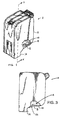
- FIG. 1 is an isometric drawing of a multi-chamber vented foam-filled ink jet print cartridge having a wall cut away to show an ink level indicator according to a first embodiment of the present invention
- FIG. 2 is a perspective drawing showing a bottom plan view of the ink jet print cartridge in FIG. 1;
- FIG. 3 is a side elevation drawing of the print cartridge in FIG. 1;
- FIG. 4 is an isometric exploded drawing of the print cartridge in FIG. 1;
- FIGS. 5A and 5B are schematic drawings of the ink level indicator in FIG. 1 showing a window of stepped thickness and a foam member, prior to and after assembly in the print cartridge in FIG. 1 respectively;
- FIGS. 6A and 6B are similar to FIGS. 5A and 5B with slits cut in the foam member to correspond with steps in the window;
- FIGS. 7A and 7B are schematic drawings of an ink level indicator according to a second embodiment of the present invention, showing a flat window and a foam member having a stepped protrusion, prior to and after assembly;
- FIGS. 8A and 8B are similar to FIGS. 7A and 7B with slits cut in the foam to allow portions of the foam member to be independently compressed;
- FIGS. 9A and 9B are similar to FIGS. 5A and 5B an ink level indicator according to a third embodiment of the present invention.
- FIG. 1 shows an isometric drawing of a multi-chamber ink jet print cartridge 2 having a wall cut away to reveal one of three ink level indicators 4 according to a first embodiment of the present invention.
- the print cartridge 2 has three separate chambers or reservoirs 6 (FIG. 4) for containing three hues of ink.
- Each of the ink level indicators 4 includes a window 8 that interacts with a porous material member, such as a synthetic foam member 10 , in the respective reservoir 6 to indicate to a user the amount of ink residual in the reservoir 6 .
- the window 8 is disposed on the print cartridge 2 to allow a user to view through the window 8 when light falls on the window 8 as shown in FIG. 2.
- FIG. 3 is a side elevation of the print cartridge 2 having a wall cut away to show one of the ink level indicators 4 .
- FIG. 4 is an exploded drawing of the print cartridge.
- a window 8 a has steps 38 a - 38 e (FIG. 5A) of varying thickness.
- This window 8 a when disposed or pressed against a foam member 10 a compresses the foam member 10 a by varying amounts to result in foam member sections 36 a - 36 e of varying capillarities adjacent the window 8 a .
- Each of the foam member portions 36 a - 36 e is able to retain a different amount of ink therein for a particular amount of residual ink in a reservoir 6 .
- Each of the foam member portions 36 a - 36 e thus appears different from the other foam member portions when viewed through the window to provide an indication of the particular amount of residual ink.
- the print cartridge 2 includes a body 12 having a snout portion 14 .
- the body 12 includes a main body member 16 , two side covers 18 and a center cover 20 (FIG. 4).
- the main body member 16 has a bottom wall 22 adjacent the snout portion 14 .
- the snout portion 14 supports a printhead 24 having an orifice plate 26 (FIG. 2) that functions as an ink dispensing outlet.
- Formed in the orifice plate 26 are separate groups of nozzles 28 for ejecting droplets of ink of one of the hues. Ink of each hue is ducted to its respective group of nozzles 28 through an ink pipe or standpipe (not shown) so that the inks do not mix within the print cartridge 2 .
- the foam member 10 in each reservoir 6 receives and retains the ink at an appropriate backpressure by capillary action.
- Information regarding structural details, operation and the method of manufacturing a print cartridge such as indicated by the reference numeral 2 is disclosed in U.S. Pat. No. 6,042,225.
- the window 8 of the ink level indicator 4 may be transparent or translucent.
- the window 8 may be integrally molded with the main body member 16 .
- the window 8 may be a separate plastic panel that is attached to the main body member 16 to cover an aperture 36 in the bottom wall 22 of the main body member 16 .
- Gluing, ultrasonic welding or other methods may be used to attach the window 8 to the main body member 16 .
- the window 8 is disposed adjacent the foam member 10 to interact with the foam member 10 by pressing against the foam member 10 to define foam member portions 36 a - 36 d (FIG. 5B) of predetermined increasing capillarities.
- each portion 36 a - 36 d is able to retain ink therein for viewing through the window 8 to thereby provide an overall indication of the amount of ink residual in the reservoir 6 .
- the interaction of the window 8 with the foam member 10 may be achieved in any one of several ways.
- One of these ways includes having a window 8 whose thickness increases in steps of for example 0.75 mm as shown in FIG. 5A.
- the window 8 may have a plurality of such steps, preferably more than three steps.
- FIG. 5A shows the window 8 a with five steps 38 a - 38 e and the foam member 10 a having a substantially flat section 40 disposed opposite the steps 38 a - 38 e of the window 8 a .
- the difference in height between steps may be changed depending on the type and felting of the foam member 10 a and the type of ink.
- the window 8 a is brought into compressive contact with the section 40 of the foam member 10 a as shown in FIG. 5B during assembly of the print cartridge 2 . Since the window 8 a is of non-uniform thickness, the window 8 a compresses the section 40 of the foam member 10 a by different amounts to define the foam member portions 36 a - 36 e that are of different capillarities. The window 8 a is thickest at the step 38 a . The portion 36 a of the foam member 10 a adjacent the step 38 a is therefore compressed most to have the highest capillarity. The window 8 a at step 38 e is thinnest and the portion 36 e of the foam member 10 adjacent the step 38 d may be compressed least to have the lowest capillarity.
- the step 36 e may be flush with the inner surface of the bottom wall 22 as shown in FIG. 5B such that the step 36 e does not additionally compress the felted foam member 10 a .
- the portions 36 b - 36 d of the foam member 10 in between the portions 36 a and 36 e have intermediate capillarities.
- the capillarity of the foam member portions 36 a - 36 d changes in substantially distinct steps.
- the foam portion 36 a with the highest capillarity is disposed closest to the snout portion 14 .
- slits 40 are formed in the foam member prior to assembly to define a plurality of distinct foam member portions 42 a - 42 e that correspond to the steps 38 a - 38 e as shown in FIG. 6A.
- the foam member portions 42 a - 42 e facilitate substantially independent compression of each of the plurality of portions 42 a - 42 e to produce more clearly demarcated compressed foam portions 42 a - 42 e with different capillarities as shown in FIG. 6B.
- the operation of this ink level indicator 4 will be described later.
- a foam member adjacent the window formed to be differentially compressed by a substantially flat window may be formed to include a stepped plurality of portions 44 a - 44 e for pressing against a flat window 8 b as shown in FIG. 7A.
- FIG. 7B shows the result of pressing the window 8 b and the foam member 10 b together in an assembled print cartridge 2 .
- the interaction of the flat window 8 b and the foam member 10 b results in the portions 44 a - 44 e being differentially compressed.
- These compressed portions 44 a - 44 e are similar to those in FIG. 5B.
- slits 40 may be foamed in the foam member 10 b , as shown in FIGS. 8 A, to achieve distinct compressed foam portions, as shown in FIG. 8B.
- the compressed foam portions are similar to those discussed earlier with reference to FIGS. 6A and 6B.
- the foam member portions 42 a - 42 e will all be saturated with ink.
- the foam member portions 42 a - 42 e appear to be dark. The original color of the foam member is not easily discernible.
- the saturated foam portion members 42 a - 42 e indicate that the reservoir is in a “full” or near full condition.
- the foam member portions 42 a and 42 b may appear through the window steps 38 a and 38 b to be dark whereas the other foam member portions 42 c - 42 e appear lighter, with 42 e appearing lightest.
- Foam member portion 42 e may even hold little or no ink so that the color of the foam member 10 a is more clearly discernible.
- the foam member portions 42 a - 42 e may all hold little or no ink such that they all appear light through the window 8 a . As ink is being dispensed from the print cartridge 2 from full to empty condition, there will be lesser and lesser ink remaining in the reservoir 6 .
- Ink retained in the foam member portions 42 a - 42 e with lower capillarities will be brought by capillary action to the snout portion 14 to be dispensed first.
- one by one the foam member portions 42 a - 42 e transform from being dark to become lighter as ink is dispensed to thereby give an indication of how much ink is left in the reservoir.
- the color of the foam member 10 a becomes more discernible through the window 8 a . It can be designed such that when the print cartridge 2 is no longer able to dispense any more ink, only the foam member portion 42 a appears dark.
- all foam portion members 42 a - 42 e may become non-saturated to appear light to indicate that the reservoir is “empty” or near empty.
- color codes on an outside surface of the print cartridge may be provided to aid a user in distinguishing conditions between a “full” and an “empty” condition of the reservoir 6 .
- FIGS. 5 B, 7 B- 9 B operate in the same manner.
- the above described ink level indicator 4 provide a low cost and reliable solution to existing vented foam-filled ink jet print cartridges for indicating the amount of residual ink therein.
- the window 8 which is described in the embodiments as located on a bottom wall 22 of the print cartridge 2 may also be located elsewhere on the print cartridge 2 .
- the window 8 may be located any where on the print cartridge 2 so long as the foam member portions do not become prematurely non-saturated and appears lighter to indicate an empty condition.
- the window should ideally be located close to the snout portion of the print cartridge where ink is drawn thereto even when the reservoir is near empty.
- the thickest step 38 a of the window in FIG. 5A may also be located furthest away from the snout region 14 while the thinnest step 38 e is located closest to the snout region 14 .
- optical sensor(s) may be used with one or more of the steps 38 a - 38 e to detect the saturation levels of corresponding foam member portions 42 a - 42 e by means of a change in reflectivity of these portions.
Landscapes
- Ink Jet (AREA)
Abstract
Description
- This invention relates generally to an ink level indicator and an ink cartridge having the same and, more particularly, to ink level indicator for use in a vented foam-filled ink jet print cartridge having a window for residual ink level indication.
- The problem of monitoring the ink volume or ink level in all types of ink-jet printers with ink reservoirs has been variously addressed. So-called backpressure indicators require a plurality of complex seals within the ink cartridge assembly and are therefore relatively expensive and tend to be unreliable. Other ink volume indicators rely on a system that measures the ink bulk electrical conductivity. The electrical conductivity of ink is difficult to control and there is likelihood that future ink improvements could make such a system obsolete.
- There have also been attempts in systems to count the “dots” or ink drops dispensed from an ink jet print cartridge. The counters, actuators and sensors needed for such systems may cause the systems to be relatively expensive to build. Furthermore, accuracy may be compromised by the need to assume an average drop volume for all print cartridges. Interruptions such as caused by removal of a print cartridge from a printer or shut-down of the printer are a possible further source of unreliability since the record of the number of drops dispensed from the ink jet print cartridge since the last update is likely to be lost.
- According to an aspect of the present invention, there is provided an ink cartridge for containing dispensable ink. The ink cartridge includes a cartridge body and a reservoir for receiving and storing ink within the cartridge body. The reservoir is filled with a porous material member. A window is supported by the cartridge body to be disposed adjacent the porous material member. The window interacts with the porous material member to define porous material member portions of predetermined increasing capillarities. Each portion is able to retain ink therein for viewing through the window depending on its capillarity and the amount of ink in the reservoir to thereby provide an overall indication of the amount of ink.
- According to another aspect of the present invention, there is provided an indicator for indicating the amount of residual ink in a reservoir of an ink cartridge. The indicator includes a foam member in the reservoir and a window disposed against the foam member to define foam member portions that have predetermined varying capillarities. Each of the foam member portions is able to retain a different amount of ink therein for a particular amount of residual ink in the reservoir to appear different from the other foam member portions. The foam member portions when viewed through the window thus provide an indication of the particular amount of residual ink in the reservoir.
- The invention will be better understood with reference to the drawings, in which:
- FIG. 1 is an isometric drawing of a multi-chamber vented foam-filled ink jet print cartridge having a wall cut away to show an ink level indicator according to a first embodiment of the present invention;
- FIG. 2 is a perspective drawing showing a bottom plan view of the ink jet print cartridge in FIG. 1;
- FIG. 3 is a side elevation drawing of the print cartridge in FIG. 1;
- FIG. 4 is an isometric exploded drawing of the print cartridge in FIG. 1;
- FIGS. 5A and 5B are schematic drawings of the ink level indicator in FIG. 1 showing a window of stepped thickness and a foam member, prior to and after assembly in the print cartridge in FIG. 1 respectively;
- FIGS. 6A and 6B are similar to FIGS. 5A and 5B with slits cut in the foam member to correspond with steps in the window;
- FIGS. 7A and 7B are schematic drawings of an ink level indicator according to a second embodiment of the present invention, showing a flat window and a foam member having a stepped protrusion, prior to and after assembly;
- FIGS. 8A and 8B are similar to FIGS. 7A and 7B with slits cut in the foam to allow portions of the foam member to be independently compressed; and
- FIGS. 9A and 9B are similar to FIGS. 5A and 5B an ink level indicator according to a third embodiment of the present invention.
- Hereafter, preferred embodiments of the present invention will be described in the context of an ink jet print cartridge. However, it is to be understood that the invention is usable with any type of ink cartridge having a reservoir that is filled with a porous material member.
- FIG. 1 shows an isometric drawing of a multi-chamber ink
jet print cartridge 2 having a wall cut away to reveal one of threeink level indicators 4 according to a first embodiment of the present invention. Theprint cartridge 2 has three separate chambers or reservoirs 6 (FIG. 4) for containing three hues of ink. Each of theink level indicators 4 includes awindow 8 that interacts with a porous material member, such as asynthetic foam member 10, in the respective reservoir 6 to indicate to a user the amount of ink residual in the reservoir 6. Thewindow 8 is disposed on theprint cartridge 2 to allow a user to view through thewindow 8 when light falls on thewindow 8 as shown in FIG. 2. FIG. 3 is a side elevation of theprint cartridge 2 having a wall cut away to show one of theink level indicators 4. FIG. 4 is an exploded drawing of the print cartridge. - According to one embodiment of the present invention, a
window 8 a has steps 38 a-38 e (FIG. 5A) of varying thickness. Thiswindow 8 a when disposed or pressed against afoam member 10 a compresses thefoam member 10 a by varying amounts to result infoam member sections 36 a-36 e of varying capillarities adjacent thewindow 8 a. Each of thefoam member portions 36 a-36 e is able to retain a different amount of ink therein for a particular amount of residual ink in a reservoir 6. Each of thefoam member portions 36 a-36 e thus appears different from the other foam member portions when viewed through the window to provide an indication of the particular amount of residual ink. - The
print cartridge 2 includes abody 12 having asnout portion 14. Thebody 12 includes amain body member 16, two side covers 18 and a center cover 20 (FIG. 4). Themain body member 16 has abottom wall 22 adjacent thesnout portion 14. Thesnout portion 14 supports aprinthead 24 having an orifice plate 26 (FIG. 2) that functions as an ink dispensing outlet. Formed in theorifice plate 26 are separate groups of nozzles 28 for ejecting droplets of ink of one of the hues. Ink of each hue is ducted to its respective group of nozzles 28 through an ink pipe or standpipe (not shown) so that the inks do not mix within theprint cartridge 2. Thefoam member 10 in each reservoir 6 receives and retains the ink at an appropriate backpressure by capillary action. Information regarding structural details, operation and the method of manufacturing a print cartridge such as indicated by thereference numeral 2 is disclosed in U.S. Pat. No. 6,042,225. - One of the
ink level indicators 4 is described in more details next with the aid of FIGS. 5A-9B. Thewindow 8 of theink level indicator 4 may be transparent or translucent. Thewindow 8 may be integrally molded with themain body member 16. Alternatively, thewindow 8 may be a separate plastic panel that is attached to themain body member 16 to cover anaperture 36 in thebottom wall 22 of themain body member 16. Gluing, ultrasonic welding or other methods may be used to attach thewindow 8 to themain body member 16. In an assembledprint cartridge 2, thewindow 8 is disposed adjacent thefoam member 10 to interact with thefoam member 10 by pressing against thefoam member 10 to definefoam member portions 36 a-36 d (FIG. 5B) of predetermined increasing capillarities. Depending on the amount of ink in the reservoir 6 and the capillarities of thefoam member portions 36 a-36 d, eachportion 36 a-36 d is able to retain ink therein for viewing through thewindow 8 to thereby provide an overall indication of the amount of ink residual in the reservoir 6. - The interaction of the
window 8 with thefoam member 10 may be achieved in any one of several ways. One of these ways includes having awindow 8 whose thickness increases in steps of for example 0.75 mm as shown in FIG. 5A. Thewindow 8 may have a plurality of such steps, preferably more than three steps. FIG. 5A shows thewindow 8 a with five steps 38 a-38 e and thefoam member 10 a having a substantiallyflat section 40 disposed opposite the steps 38 a-38 e of thewindow 8 a. The difference in height between steps may be changed depending on the type and felting of thefoam member 10 a and the type of ink. - The
window 8 a is brought into compressive contact with thesection 40 of thefoam member 10 a as shown in FIG. 5B during assembly of theprint cartridge 2. Since thewindow 8 a is of non-uniform thickness, thewindow 8 a compresses thesection 40 of thefoam member 10 a by different amounts to define thefoam member portions 36 a-36 e that are of different capillarities. Thewindow 8 a is thickest at thestep 38 a. The portion 36 a of thefoam member 10 a adjacent thestep 38 a is therefore compressed most to have the highest capillarity. Thewindow 8 a atstep 38 e is thinnest and theportion 36 e of thefoam member 10 adjacent thestep 38 d may be compressed least to have the lowest capillarity. Alternatively, thestep 36 e may be flush with the inner surface of thebottom wall 22 as shown in FIG. 5B such that thestep 36 e does not additionally compress the feltedfoam member 10 a. Theportions 36 b-36 d of thefoam member 10 in between theportions 36 a and 36 e have intermediate capillarities. In such an implementation, the capillarity of thefoam member portions 36 a-36 d changes in substantially distinct steps. Preferably, the foam portion 36 a with the highest capillarity is disposed closest to thesnout portion 14. - To further enhance the distinctiveness of each of these
foam portions 36 a-36 e, slits 40 are formed in the foam member prior to assembly to define a plurality of distinct foam member portions 42 a-42 e that correspond to the steps 38 a-38 e as shown in FIG. 6A. When pressed against thewindow 8 a, the foam member portions 42 a-42 e facilitate substantially independent compression of each of the plurality of portions 42 a-42 e to produce more clearly demarcated compressed foam portions 42 a-42 e with different capillarities as shown in FIG. 6B. The operation of thisink level indicator 4 will be described later. - Another way of achieving the foam portions of different capillarities is to have a foam member adjacent the window formed to be differentially compressed by a substantially flat window. For example, a foam member 10 b may be formed to include a stepped plurality of portions 44 a-44 e for pressing against a flat window 8 b as shown in FIG. 7A. FIG. 7B shows the result of pressing the window 8 b and the foam member 10 b together in an assembled
print cartridge 2. The interaction of the flat window 8 b and the foam member 10 b results in the portions 44 a-44 e being differentially compressed. These compressed portions 44 a-44 e are similar to those in FIG. 5B. - Similarly slits 40 may be foamed in the foam member 10 b, as shown in FIGS. 8A, to achieve distinct compressed foam portions, as shown in FIG. 8B. The compressed foam portions are similar to those discussed earlier with reference to FIGS. 6A and 6B.
- The distinct steps in capillarity in the compressed state of the foam member as shown in FIGS. 5A-8B may be replaced with a foam member that is compressed to define a section of the foam member with a capillarity that increases gradually. FIG. 9A shows a wedge-shaped window 8 c with an
inclined surface 50 disposed opposite a substantiallyflat section 52 of a foam member 10 c. When theinclined surface 50 of the window 8 c is pressed against thesection 52 of the foam member, the capillarity of a portion of the pressed section of the foam member 10 c is changed by an amount corresponding to the thickness of the window immediately adjacent the portion. Thesection 52 is therefore compressed to have a capillarity that increases in the direction of an arrow B in FIG. 9B. Such gradual increase in capillarity is achievable with a flat window pressing against a protruding wedged portion of a foam member in a manner similar to that shown in FIGS. 7A-8B. - The operation of the
ink level indicator 4 in FIG. 6B is described next. When the reservoir 6 is fully filled with ink, the foam member portions 42 a-42 e will all be saturated with ink. When viewed from the outside of thewindow 8 a, the foam member portions 42 a-42 e appear to be dark. The original color of the foam member is not easily discernible. The saturated foam portion members 42 a-42 e indicate that the reservoir is in a “full” or near full condition. When ink is dispensed such that the reservoir 6 is for example about “half full”, thefoam member portions 42 a and 42 b may appear through the window steps 38 a and 38 b to be dark whereas the otherfoam member portions 42 c-42 e appear lighter, with 42 e appearing lightest.Foam member portion 42 e may even hold little or no ink so that the color of thefoam member 10 a is more clearly discernible. When the reservoir 6 is empty of near empty, the foam member portions 42 a-42 e may all hold little or no ink such that they all appear light through thewindow 8 a. As ink is being dispensed from theprint cartridge 2 from full to empty condition, there will be lesser and lesser ink remaining in the reservoir 6. Ink retained in the foam member portions 42 a-42 e with lower capillarities will be brought by capillary action to thesnout portion 14 to be dispensed first. In this manner, one by one the foam member portions 42 a-42 e transform from being dark to become lighter as ink is dispensed to thereby give an indication of how much ink is left in the reservoir. As ink is drawn away from the foam member portions 42 a-42 e, the color of thefoam member 10 a becomes more discernible through thewindow 8 a. It can be designed such that when theprint cartridge 2 is no longer able to dispense any more ink, only thefoam member portion 42 a appears dark. Alternatively, all foam portion members 42 a-42 e may become non-saturated to appear light to indicate that the reservoir is “empty” or near empty. In such an implementation, color codes on an outside surface of the print cartridge may be provided to aid a user in distinguishing conditions between a “full” and an “empty” condition of the reservoir 6. The other embodiments in FIGS. 5B, 7B-9B operate in the same manner. - Advantageously, the above described
ink level indicator 4 according to the various embodiments of the present invention provide a low cost and reliable solution to existing vented foam-filled ink jet print cartridges for indicating the amount of residual ink therein. - Although the present invention is described according to the different embodiments above, it should not be construed to be limited as such. For example, the invention may be implemented in any foam-filled ink cartridge used for other imprinting apparatus.
- As another example, the
window 8 which is described in the embodiments as located on abottom wall 22 of theprint cartridge 2 may also be located elsewhere on theprint cartridge 2. Thewindow 8 may be located any where on theprint cartridge 2 so long as the foam member portions do not become prematurely non-saturated and appears lighter to indicate an empty condition. As such, the window should ideally be located close to the snout portion of the print cartridge where ink is drawn thereto even when the reservoir is near empty. - As yet another example, the
thickest step 38 a of the window in FIG. 5A may also be located furthest away from thesnout region 14 while thethinnest step 38 e is located closest to thesnout region 14. - As a further example, optical sensor(s) may be used with one or more of the steps 38 a-38 e to detect the saturation levels of corresponding foam member portions 42 a-42 e by means of a change in reflectivity of these portions.
Claims (20)
Priority Applications (1)
| Application Number | Priority Date | Filing Date | Title |
|---|---|---|---|
| US10/119,667 US6857731B2 (en) | 2002-04-10 | 2002-04-10 | Ink level indicator and ink cartridge having the same |
Applications Claiming Priority (1)
| Application Number | Priority Date | Filing Date | Title |
|---|---|---|---|
| US10/119,667 US6857731B2 (en) | 2002-04-10 | 2002-04-10 | Ink level indicator and ink cartridge having the same |
Publications (2)
| Publication Number | Publication Date |
|---|---|
| US20030193552A1 true US20030193552A1 (en) | 2003-10-16 |
| US6857731B2 US6857731B2 (en) | 2005-02-22 |
Family
ID=28789961
Family Applications (1)
| Application Number | Title | Priority Date | Filing Date |
|---|---|---|---|
| US10/119,667 Expired - Lifetime US6857731B2 (en) | 2002-04-10 | 2002-04-10 | Ink level indicator and ink cartridge having the same |
Country Status (1)
| Country | Link |
|---|---|
| US (1) | US6857731B2 (en) |
Cited By (2)
| Publication number | Priority date | Publication date | Assignee | Title |
|---|---|---|---|---|
| JP2021192993A (en) * | 2020-01-28 | 2021-12-23 | セイコーエプソン株式会社 | Liquid injection device |
| US11376860B2 (en) | 2017-07-17 | 2022-07-05 | Hewlett-Packard Development Company, L.P. | Printing fluid container |
Families Citing this family (8)
| Publication number | Priority date | Publication date | Assignee | Title |
|---|---|---|---|---|
| US7036904B2 (en) * | 2003-10-30 | 2006-05-02 | Lexmark International, Inc. | Printhead swath height measurement and compensation for ink jet printing |
| US7524016B2 (en) * | 2004-01-21 | 2009-04-28 | Silverbrook Research Pty Ltd | Cartridge unit having negatively pressurized ink storage |
| US7448734B2 (en) | 2004-01-21 | 2008-11-11 | Silverbrook Research Pty Ltd | Inkjet printer cartridge with pagewidth printhead |
| US7469989B2 (en) * | 2004-01-21 | 2008-12-30 | Silverbrook Research Pty Ltd | Printhead chip having longitudinal ink supply channels interrupted by transverse bridges |
| US20050157112A1 (en) | 2004-01-21 | 2005-07-21 | Silverbrook Research Pty Ltd | Inkjet printer cradle with shaped recess for receiving a printer cartridge |
| US7441865B2 (en) | 2004-01-21 | 2008-10-28 | Silverbrook Research Pty Ltd | Printhead chip having longitudinal ink supply channels |
| US7367650B2 (en) * | 2004-01-21 | 2008-05-06 | Silverbrook Research Pty Ltd | Printhead chip having low aspect ratio ink supply channels |
| JP2007168132A (en) * | 2005-12-19 | 2007-07-05 | Ricoh Co Ltd | Image forming apparatus |
Citations (4)
| Publication number | Priority date | Publication date | Assignee | Title |
|---|---|---|---|---|
| US5079570A (en) * | 1989-10-18 | 1992-01-07 | Hewlett-Packard Company | Capillary reservoir binary ink level sensor |
| US5652610A (en) * | 1993-05-13 | 1997-07-29 | Canon Kabushiki Kaisha | Ink tank, ink tank-integrated head cartridge having the tank and ink head constructed integrally, and ink jet printing apparatus having the ink tank or head cartridge |
| US6367919B1 (en) * | 2000-07-13 | 2002-04-09 | Hewlett-Packard Company | Ink container with ink level gauge |
| US6457793B1 (en) * | 2001-04-03 | 2002-10-01 | Hewlett-Packard Company | Screen color for detecting ink level for foam based ink supplies |
Family Cites Families (2)
| Publication number | Priority date | Publication date | Assignee | Title |
|---|---|---|---|---|
| JPH04224771A (en) * | 1990-12-27 | 1992-08-14 | Tokyo Electric Co Ltd | low frequency treatment device |
| JP3217141B2 (en) * | 1992-07-31 | 2001-10-09 | 株式会社ブリヂストン | Foam for holding ink |
-
2002
- 2002-04-10 US US10/119,667 patent/US6857731B2/en not_active Expired - Lifetime
Patent Citations (4)
| Publication number | Priority date | Publication date | Assignee | Title |
|---|---|---|---|---|
| US5079570A (en) * | 1989-10-18 | 1992-01-07 | Hewlett-Packard Company | Capillary reservoir binary ink level sensor |
| US5652610A (en) * | 1993-05-13 | 1997-07-29 | Canon Kabushiki Kaisha | Ink tank, ink tank-integrated head cartridge having the tank and ink head constructed integrally, and ink jet printing apparatus having the ink tank or head cartridge |
| US6367919B1 (en) * | 2000-07-13 | 2002-04-09 | Hewlett-Packard Company | Ink container with ink level gauge |
| US6457793B1 (en) * | 2001-04-03 | 2002-10-01 | Hewlett-Packard Company | Screen color for detecting ink level for foam based ink supplies |
Cited By (2)
| Publication number | Priority date | Publication date | Assignee | Title |
|---|---|---|---|---|
| US11376860B2 (en) | 2017-07-17 | 2022-07-05 | Hewlett-Packard Development Company, L.P. | Printing fluid container |
| JP2021192993A (en) * | 2020-01-28 | 2021-12-23 | セイコーエプソン株式会社 | Liquid injection device |
Also Published As
| Publication number | Publication date |
|---|---|
| US6857731B2 (en) | 2005-02-22 |
Similar Documents
| Publication | Publication Date | Title |
|---|---|---|
| US4673955A (en) | Ink receptacle for ink jet printer | |
| EP0714778B1 (en) | Ink jet recorder and method of cleaning recording head | |
| US4771295A (en) | Thermal ink jet pen body construction having improved ink storage and feed capability | |
| AU689297B2 (en) | Ink-supplied printer and ink supply tank | |
| EP0645243B1 (en) | Refillable ink jet printing module | |
| EP0674998B1 (en) | Ink jet printer cartridge refilling method and apparatus | |
| US7828421B2 (en) | Ink cartridge arrangements | |
| US5971531A (en) | Ink jet cartridge having replaceable ink supply tanks with an internal filter | |
| US6857731B2 (en) | Ink level indicator and ink cartridge having the same | |
| US6070976A (en) | Ink tank and recording apparatus | |
| JP4453400B2 (en) | ink cartridge | |
| WO2007037536A9 (en) | Ink cartridge and method for replacing ink reservoir element in ink cartridge | |
| US20100085398A1 (en) | Ink surface detecting systems and ink cartridge | |
| EP2165837B1 (en) | Liquid ejecting apparatus and liquid ejecting system | |
| US8025376B2 (en) | Ink cartridges | |
| US6412929B1 (en) | Apparatus for supplying fluid to an ink jet nozzle | |
| JPH0920014A (en) | Ink container and ink replenisher for ink jet recorder | |
| EP1388419B1 (en) | Ink tank and ink jet printer incorporating the same | |
| WO2007037451A1 (en) | Ink cartridge, ink jet recording system and set of ink cartridges | |
| US7810916B2 (en) | Ink cartridges | |
| US7553007B2 (en) | Ink cartridges | |
| JP4192500B2 (en) | Inkjet recording device | |
| US7837311B2 (en) | Ink cartridges | |
| US7682004B2 (en) | Ink cartridges | |
| US7775645B2 (en) | Methods of forming cartridges, such as ink cartridges |
Legal Events
| Date | Code | Title | Description |
|---|---|---|---|
| AS | Assignment |
Owner name: HEWLETT-PACKARD COMPANY, COLORADO Free format text: ASSIGNMENT OF ASSIGNORS INTEREST;ASSIGNOR:THAM, HING CHING;REEL/FRAME:012932/0123 Effective date: 20020319 |
|
| AS | Assignment |
Owner name: HEWLETT-PACKARD DEVELOPMENT COMPANY, L.P., COLORADO Free format text: ASSIGNMENT OF ASSIGNORS INTEREST;ASSIGNOR:HEWLETT-PACKARD COMPANY;REEL/FRAME:013776/0928 Effective date: 20030131 Owner name: HEWLETT-PACKARD DEVELOPMENT COMPANY, L.P., COLORAD Free format text: ASSIGNMENT OF ASSIGNORS INTEREST;ASSIGNOR:HEWLETT-PACKARD COMPANY;REEL/FRAME:013776/0928 Effective date: 20030131 Owner name: HEWLETT-PACKARD DEVELOPMENT COMPANY, L.P.,COLORADO Free format text: ASSIGNMENT OF ASSIGNORS INTEREST;ASSIGNOR:HEWLETT-PACKARD COMPANY;REEL/FRAME:013776/0928 Effective date: 20030131 |
|
| STCF | Information on status: patent grant |
Free format text: PATENTED CASE |
|
| FPAY | Fee payment |
Year of fee payment: 4 |
|
| REMI | Maintenance fee reminder mailed | ||
| FPAY | Fee payment |
Year of fee payment: 8 |
|
| FPAY | Fee payment |
Year of fee payment: 12 |