JP4192500B2 - Inkjet recording device - Google Patents
Inkjet recording device Download PDFInfo
- Publication number
- JP4192500B2 JP4192500B2 JP2002153291A JP2002153291A JP4192500B2 JP 4192500 B2 JP4192500 B2 JP 4192500B2 JP 2002153291 A JP2002153291 A JP 2002153291A JP 2002153291 A JP2002153291 A JP 2002153291A JP 4192500 B2 JP4192500 B2 JP 4192500B2
- Authority
- JP
- Japan
- Prior art keywords
- ink
- tank
- main
- ink tank
- sub
- Prior art date
- Legal status (The legal status is an assumption and is not a legal conclusion. Google has not performed a legal analysis and makes no representation as to the accuracy of the status listed.)
- Expired - Fee Related
Links
Images


Description
【0001】
【発明の属する技術分野】
本発明は、インクジェットプリンタ等のインクジェット記録装置に関し、とくにサブインクタンクと記録ヘッドが一体化してキャリッジ上に搭載され、サブインクタンクとメインインクタンクがチューブ等で接続されており、インクの消費に応じてサブインクタンクと接続されたメインインクタンクを交換可能なインクジェット記録装置に関する。
【0002】
【従来の技術】
記録ヘッドに設けられたインク吐出口からインクを吐出させて記録を行うシリアル型インクジェット記録装置として、従来、記録ヘッド上にインクタンクを搭載したキャリッジを往復走査させて記録を行うものが知られている。
【0003】
このような従来のインクジェット記録装置では、キャリッジ上に複数の種類のインクを収納したインクタンクが搭載される。インクタンクは、記録ヘッドからのインクだれを防止するため、定常状態において負圧に維持される必要がある都合上、インクタンク内にスポンジ等の多孔質負圧発生部材を必要とし、充分なインク量を保持するためには、インクタンクの容積がインクの内容量に対してかなり大きなものとなってしまい、結果としてキャリッジの大型化を招いていた。
【0004】
このような問題を回避するため、装置本体側に固定されたメインインクタンクから柔軟性を有するチューブ等により接続したサブインクタンクを介して記録ヘッドにインクを供給するインク供給系が用いられている。
【0005】
このような方法を用いると、非常に簡単な構成でインク供給系が実現でき、キャリッジ上のサブインクタンクには、スポンジ等の負圧発生部材を必要としない、内容積が1cc程度の小型のサブインクタンクを搭載するだけでよいので、キャリッジの小型化が可能となる。また、メインインクタンクを記録ヘッドの吐出口面より20〜100mm程度低い位置に設けることで、水頭圧差によりメインインクタンク内に前述の負圧発生部材が必要でなくなり、メインインクタンクの容積に対するインク充填効率が向上する。
【0006】
【発明が解決しようとする課題】
メインインクタンクとサブインクタンクを接続する柔軟性のあるチューブは、ゴム製、樹脂製のものが用いられるため、若干のガス透過性を有する。また、チューブ内も記録ヘッドと同等に負圧になっているため、チューブ内には大気からチューブ壁を介して少しづつ空気が進入し、長期放置時等において気泡が発生する。さらに、メインインクタンク交換時にもチューブ内に気泡が進入してしまう。そして、この気泡が記録ヘッドに流れ込むと、正常なインク滴を吐出できなくなり、印字不良が発生する。
【0007】
このような印字不良状態を回避するために、装置の状態や使用者の指示により、吸引回復動作が行われる。
【0008】
吸引回復動作は、記録ヘッドの吐出口面にキャップ部材を押圧し、インク吸引手段を動作させ、吐出口からインクを吸引して、メインインクタンクから記録ヘッドにインクを充填させることで実現される。
【0009】
しかしながら、従来の装置では、この回復動作を確実に行うために、インク吸引手段が記録ヘッドからメインインクタンクまでの全てのインク流路の体積に相当するインクを吸引するように設定されている。このため、インク流路に残存しているインクを全て廃棄することとなり、実際に記録に用いることのできるインク量が減り、インクの使用効率が大幅に低下する。
【0010】
本発明の目的は、上記の問題を解決し、メインインクタンクから記録ヘッドまでのインク流路におけるインクの残存状態に応じたインク量を吸引することにより、廃棄するインク量を最小限にすることができるインクジェット記録装置を提供することにある。
【0011】
【課題を解決するための手段および発明の効果】
本発明によるインクジェット記録装置は、吐出口形成面に形成された吐出口からインクを吐出して記録を行う記録ヘッドと、該記録ヘッドへインクを供給するために前記記録ヘッドと一体状に形成されたサブインクタンクと、前記記録ヘッドおよびサブインクタンクを搭載し所定の記録領域およびその隣接領域を主走査方向に移動可能なキャリッジと、前記サブインクタンクへインクを供給可能なメインインクタンクと、前記サブインクタンクとメインインクタンクを接続し前記メインインクタンクと当接および離脱が可能な接続手段と、前記隣接領域に配設され前記記録ヘッドの吐出口形成面に対して当接および離脱が可能なキャップ部材と、該キャップ部材を介して前記記録ヘッドの吐出口からインクを吸引する吸引手段と、該吸引手段を制御する制御手段とを備えているインクジェット記録装置において、前記サブインクタンク内のインク残量の有無を検知する第1のインク残量検知手段を備えており、前記制御手段は、前記吸引手段に、初期充填時の吸引回復動作と、前記第1のインク残量検知手段の検知結果によってインク吸引量の異なる2つの吸引回復動作とから 1 つを選択して行わせるものであることを特徴とするものである。
【0012】
メインインクタンクは、装置本体側に固定状に設けられる。
【0013】
接続手段は、通常は、メインインクタンクに当接されており、メインインクタンクの交換時に、メインインクタンクから離脱される。
【0014】
吸引回復動作は、回復動作指示があったときに行われる。回復動作指示は、装置の状態によって自動的に出力される。また、使用者の回復動作の操作によっても出力される。
【0015】
たとえば、残量検知手段の検知結果が残量ありの場合は、小回復シーケンスが行われる。これは、記録ヘッド内のインクをリフレッシュするためにごく少量のインクを短時間吸引する回復動作である。残量検知手段の検知結果が残量なしの場合は、中回復シーケンスが行われる。これは、サブインクタンク内に一定量のインクを吸引するために、小回復シーケンスよりは多いが、比較的少量のインクを吸引する回復動作である。
【0016】
また、初期充填時、すなわち、装置を初めて使用する場合や装置が長時間放置された場合は、大回復シーケンスが行われる。これは、長時間インクを吸引し、メインインクタンクから接続手段、サブインクタンクおよび記録ヘッドにインクを充填して、印字が開始できるようにする回復動作である。
【0017】
本発明のインクジェット記録装置によれば、初期充填であるか否かと、第1のインク残量検知手段の検知結果、すなわち、サブインクタンク内のインク残量の有無とに応じて、適正なインク吸引動作を行わせることができる。したがって、吸引回復動作によって無駄なインクを廃棄することがなく、インクの使用効率が向上し、メインインクタンクの小型化、廃インクパッドの小型化、コスト削減、ひいてはインクジェット記録装置全体の小型化が可能となる。
【0018】
本発明のインクジェット記録装置において、たとえば、前記メインインクタンク内のインク残量の有無を検知する第2のインク残量検知手段を備え、前記制御手段が、前記第2のインク残量検知手段の検知結果に応じて、前記メインインクタンクの交換を指示するものである。
【0019】
これによれば、メインインクタンクの交換が必要になったときに、確実に交換を指示することができる。
【0020】
本発明のインクジェット記録装置において、たとえば、前記接続手段の前記メインインクタンクと当接する部分に、前記メインインクタンク離脱時に前記接続手段への空気の進入を防止するフィルタ部材が設けられている。
【0021】
これによれば、フィルタ部材にインク膜が形成されるため、メインインクタンク交換のために接続手段からメインインクタンクを離脱したときに、接続手段に空気が進入することがない。したがって、メインインクタンクを交換した後に、必ずしも吸引回復動作を行う必要がなく、インクの廃棄量をさらに少なくすることができる。
【0022】
たとえば、記録ヘッドに、複数のサブインクタンクが一体化され、各サブインクタンクにそれぞれ対応する複数の吐出口が形成されている。
【0023】
また、たとえば、記録ヘッドは、分極された圧電部材に電界を作用させることにより、圧電部材に剪断変形を生じさせ、インク室に充填されたインクに圧力波を作用させてインクを吐出するものである。
【0024】
【発明の実施の形態】
以下、図面を参照して、本発明をインクジェットプリンタに適用した実施形態について説明する。
【0025】
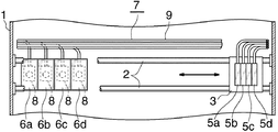
図1はプリンタの印字部を記録用紙の搬送方向後側(上流側)から見た部分切欠き背面図、図2は同部分切欠き平面図である。実施形態の説明において、前後左右は印字部における記録用紙の搬送方向についていうものとする。印字部において、記録用紙は図1の紙面表側から紙面裏側に搬送されるので、図2の上側(図1の紙面裏側)が前、図2の下側(図1の紙面表側)が後であり、図1および図2の左右が左右である。
【0026】
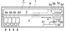
図1および図2に示すように、プリンタの印字部には、装置本体の筐体(1)に固定されて主走査方向である左右方向にのびるガイド棒(2)が設けられ、これにキャリッジ(3)が取り付けられている。キャリッジ(3)は、図示しない適宜の駆動手段により、ガイド棒(2)に沿って左右方向に移動させられる。キャリッジ(3)の移動領域のうち、右端部を除く領域が、印字時にキャリッジ(3)が往復移動する記録領域、記録領域に隣接する右端部の領域がメンテナンス領域となっている。
【0027】
キャリッジ(3)には、記録ヘッド(4)と複数(この例では4つ)のサブインクタンク(5a)(5b)(5c)(5d)が搭載されている。サブインクタンクは、符号(5)で総称する。サブタンク(5)は、記録ヘッド(4)の上に一体状に設けられている。
【0028】
図示は省略したが、記録ヘッド(4)の下面の吐出口形成面に、各サブタンク(5)にそれぞれ対応する複数の吐出口が形成されている。そして、記録ヘッド(4)は、分極された圧電部材に電界を作用させることにより、圧電部材に剪断変形を生じさせ、インク室に充填されたインクに圧力波を作用させてインクを吐出するようになっている。
【0029】
筐体(1)内の下部に、サブタンク(5)と同数のメインインクタンク(6a)(6b)(6c)(6d)が着脱可能に設けられている。メインインクタンクは、符号(6)で総称する。そして、メインタンク(6)とサブタンク(5)の対応するもの同士が、接続手段を構成する接続装置(7)により接続されている。図示は省略したが、メインタンク(6)は、筐体(1)に設けられたホルダに装着され、それにより、接続装置(7)に当接して、対応するサブタンク(5)に接続される。
【0030】
サブタンク(5)の詳細が図3に、メインタンク(6)の詳細が図4に、接続装置(7)の詳細が図5に示されている。
【0031】
接続装置(7)は、筐体(1)に固定状に設けられてメインタンク(6)と当接および離脱が可能な接続ブロック(8)と、接続ブロック(8)とサブタンク(5)を接続するチューブ(9)とから構成されている。詳細な図示は省略したが、チューブ(9)はカバー部材によって束ねられて、保護され、キャリッジ(3)の移動の妨げにならないようになっている。
【0032】
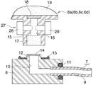
図5に示すように、接続ブロック(8)は直方体状をなし、1つの側面から上面に達するインク流路(10)が形成されている。流路(10)の側面側には、チューブ(9)の端部が挿入されて、固定され、シール部材(11)により密封されている。流路(10)の上面開口部には、短い円筒部(12)が一体に形成されている。円筒部(12)の周囲のブロック(8)の上面に、シール部材(13)が設けられている。円筒部(12)の量路(10)の上端開口には、フィルタ部材(14)が設けられている。
【0033】
図4に示すように、メインタンク(6)は、略直方体状をなし、その下面に円柱部(15)が一体に形成されている。円柱部(15)には、それを上下に貫通してメインタンク(6)の内部と連通するインク流路(16)が形成されている。流路(16)の下端開口部は他の部分より内径が大きくなっており、この部分にスポンジ等の多孔質部材(17)がはめ入れられている。また、流路(16)の上端部とメインタンク(6)の内部との間には、フィルタ部材(18)が設けられている。
【0034】
メインタンク(6)内には、負圧を発生させるためのスポンジ等の多孔質部材(19)が充填されており、メインタンク(6)の上壁には、大気連通穴(20)が形成されている。
【0035】
図3に示すように、サブタンク(5)の1側面の下部に、サブタンク(5)の内部と連通する中空状の突出部(21)が形成され、この突出部(21)の先端部にチューブ(9)が接続されている。通常、サブタンク(5)の下側約半分の部分にインクが充填され、上側の約半分の部分が空気層となっている。サブタンク(5)の底壁に、記録ヘッド(4)へのインク供給穴(22)が形成されている。サブタンク(5)内のインク供給穴(22)が形成された部分と、突出部(21)側の部分との間に、キャリッジ(3)の動作によるインクの流動が直接記録ヘッド(4)に伝わることを防止する仕切壁(23)が設けられている。空気層と仕切壁(23)により、キャリッジ(3)の加減速時のインクの流動の影響を最小限にしている。
【0036】
メインタンク(6)の内容量は、サブタンク(5)の内容量より充分大きい。サブタンク(5)の少なくとも突出部(21)は、透明プラスチックス等の透光性材料で作られている。たとえば、サブタンク(5)全体が透光性材料で作られている。そして、突出部(21)に、第1のインク残量検知手段を構成する第1のインク残量センサ(24)が設けられている。このセンサ(24)は、突出部(21)を挟んで対向状に配置された発光素子(25)と受光素子(26)とからなり、受光素子(26)から突出部(21)内すなわちサブタンク(5)内のインク残量に応じた電気信号が出力される。そして、これにより、サブタンク(5)内のインク残量の有無が検知される。メインタンク(6)の円柱部(15)に、第2のインク残量検知手段を構成する第2のインク残量センサ(27)が設けられている。このセンサ(27)は、流路(16)を挟むように円柱部(15)の両外側面に1対の電極(28)(29)より構成されている。図示は省略したが、メインタンク(6)がホルダに装着されたときに、センサ(27)の電極(28)(29)がホルダ側に設けられた電極に接触し、電極(28)(29)間に交流電圧が印加される。そして、電極(28)(29)間の容量を検知することにより、流路(16)内のインク残量の有無が検知される。
【0037】
メンテナンス領域に、吸引回復動作を行うためのキャップ部材(30)が上下動可能に設けられている。筐体(1)の下部に廃インク溜め(31)が設けられ、廃インク溜め(31)とキャップ部材(30)との間に、吸引手段を構成する吸引ポンプ(32)が設けられている。
【0038】
図6は、プリンタの電気的構成の主要部の1例を示している。
【0039】
プリンタは、プリンタ全体を制御するための制御部(33)を備えている。制御部(33)には、電源投入スイッチ(34)、内蔵タイマ(35)等が接続され、2つのインク残量センサ(24)(27)の出力、メンテナンス指示信号等が制御部(33)に入力する。制御部(33)は、後述するように、メンテナンス時に、メンテナンス指示信号、センサ(24)(27)の出力、内蔵タイマ(35)等に基づいて、吸引ポンプ(32)を駆動する駆動モータ(36)を制御し、これにより、吸引回復動作を制御する。
【0040】
上記のプリンタの使用を開始するとき、メインタンク(6)がホルダに装着され、これにより、メインタンク(6)の円柱部(15)がブロック(8)の円筒部(12)の外側にはまって、シール部材(13)に圧接し、これらの間が密閉される。そして、キャリッジ(3)がメンテナンス領域の所定のメンテナンス位置に停止させられ、キャップ部材(30)が上昇して、記録ヘッド(4)の吐出口形成面に当接することにより、吐出口が塞がれ、ポンプ(32)が駆動されることにより、メインタンク(6)から接続装置(7)を通してサブタンク(5)および記録ヘッド(4)にインクが充填される。
【0041】
通常の使用時には、キャリッジ(3)が記録領域を往復移動している間に、前記のように記録ヘッド(4)の吐出口からインクが吐出されることにより、記録が行われる。そして、印字のための記録ヘッド(4)からのインク吐出によりサブタンク(6)内のインクが消費されても、記録ヘッド(4)の吐出口の毛細管力により、消費された分のインクが自動的に補充され、サブタンク(5)内および接続装置(7)内が空になることはない。
【0042】
メンテナンスを行うときには、メンテナンス位置に停止したキャリッジ(3)の記録ヘッド(4)の吐出口形成面にキャップ部材(30)が当接し、ポンプ(32)が駆動されることにより、吐出口からインクが吸引されて、サブタンク(5)および記録ヘッド(4)にインクが充填される。ポンプ(32)により吸引されたインクは、廃インク溜め(31)に溜められる。
【0043】
メインタンク(6)が空になると、そのメインタンク(6)がホルダから取り外され、新しいメインタンク(6)が装着される。メインタンク(6)をホルダから取り外すと、メインタンク(6)がブロック(8)から離脱するが、ブロック(8)のフィルタ部材(14)の部分に毛細管力によってインク膜が形成され、接続装置(7)内への空気の進入が防止される。そして、新しいメインタンク(6)がホルダに装着されると、インクが充満したメインタンク(6)の多孔質部材(17)とブロック(8)のフィルタ部材(14)が密着し、毛細管力により再度インクの供給が可能となる。このため、メインタンク(6)を交換したときに、必ずしもメンテナンスを行う必要がない。なお、メインタンク(6)の多孔質部材(17)には、記録用紙1ページの印字ができる量のインクが保持されている。このため、流路(16)内にインクがなくなっても、多孔質部材(17)に保持されているインクで印字が可能である。
【0044】
制御部(33)は、吸引回復動作の実行指示を受けたとき、たとえば、プリンタが長時間放置されていたことを検知した場合や、使用者からの指示があった場合に、メンテナンスを行う。このとき、制御部(33)は、2つのインク残量センサ(24)(27)によるインク残量の有無の検知結果に基づいて、予め設定した動作時間または動作回数の異なる複数種類の吸引回復動作から最適な吸引回復動作を選択し、インク吸引量の異なる吸引回復動作を行う。
【0045】
次に、図7のフローチャートを参照して、メンテナンス時の動作の1例について説明する。
【0046】
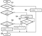
メンテナンス指示があると、まず、初期充填であるか否かが調べられ(S1)、そうであれば、大回復シーケンスが行われ(S2)、処理を終了する。初期充填であるか否かの判断は、メモリの初期充填動作フラグを参照して行われる。このフラグがセットされていると、初期充填であると判断されて、大回復シーケンスが行われ、一度大回復シーケンスが行われると、初期充填フラグはクリアされる。また、長時間プリンタが放置された場合は、内蔵タイマ(35)によって、再び初期充填フラグがセットされる。大回復シーケンスは、ポンプ(32)により長時間インクの吸引を行って、メインタンク(6)からブロック(8)、チューブ(9)、サブタンク(5)および記録ヘッド(4)までインクを充填して、印字が開始できるようにする回復動作である。
【0047】
S1において、初期充填でなかった場合は、第2のセンサ(27)の出力より、メインタンク(6)のインク残量の有無が調べられ(S3)、残量がない場合は、使用者に対してメインタンク(6)の交換指示が行われ(S4)、使用者によるメインタンク(6)の交換が完了するまで待機し(S5)、交換が完了すると、処理を終了する。
【0048】
S3において、メインタンク(6)のインク残量がある場合は、第1のセンサ(24)の出力より、サブタンク(5)のインク残量の有無が調べられ(S6)、残量がない場合は、中回復シーケンスが行われ(S7)、処理を終了する。中回復シーケンスは、サブタンク(5)内に一定量のインクを充填するための回復動作であり、インク吸引量は、大回復シーケンスの場合より少ない。
【0049】
S6において、サブタンク(5)のインク残量がある場合は、小回復シーケンスが行われ(S8)、処理を終了する。小回復シーケンスは、記録ヘッド(4)内のインクをリフレッシュするための回復動作であり、インク吸引量は最も少ない。
【0050】
上記のようにメインタンク(6)の交換を行った場合、使用者からの指示がない限り、吸引回復動作は行われない。前記のように、メインタンク(6)を取り外しても、フィルタ部材(14)に形成されたインク膜により接続装置(7)内に空気が進入することを防止できるため、回復動作を行う必要がないからである。使用者から回復動作の指示があった場合は、図7のフローチャートが実行され、上記のように、中回復シーケンスおよび小回復シーケンスのいずれかが選択されて、実行される。
【0051】
なお、印字の途中でメインタンク(6)のインク残量がなくなっても、前記のように、センサ(27)より記録ヘッド(4)側の多孔質部材(17)の部分に記録用紙1ページ分以上のインクが残るようになっているため、印字を中断することなく、印字終了後にメインタンク(6)の交換を指示することが可能である。
【0052】
上記の実施形態では、メインタンク(6)内に多孔質部材(19)が設けられて、負圧を発生するようになっているが、サブタンク(5)よりも充分に下方に設置される場合、たとえば、サブタンク(5)より100mm以上下方に設置されるような場合は、多孔質部材は不要である。
【0053】
また、上記の実施形態では、メインタンク(6)がサブタンク(7)よりも下方に設置されているが、メインタンクはサブタンクよりも上方に設置されてもよい。
【図面の簡単な説明】
【図1】図1は、本発明の実施形態を示すインクジェットプリンタの印字部の概略垂直断面図である。
【図2】図2は、図1のインクジェットプリンタの印字部の概略平面図である。
【図3】図3は、サブインクタンクの部分の垂直断面図である。
【図4】図4は、メインインクタンクの部分の垂直断面図である。
【図5】図5は、接続装置の接続ブロックの部分の垂直断面図である。
【図6】図6は、インクジェットプリンタの電気的構成の主要部の1例を示すブロック図である。
【図7】図7は、回復動作の例を示すフローチャートである。
【符号の説明】
(3) キャリッジ
(4) 記録ヘッド
(5a)(5b)(5c)(5d) サブインクタンク
(6a)(6b)(6c)(6d) メインインクタンク
(7) 接続装置
(14) フィルタ部材
(24) 第1のインク残量センサ
(27) 第2のインク残量センサ[0001]
BACKGROUND OF THE INVENTION
The present invention relates to an ink jet recording apparatus such as an ink jet printer, and in particular, a sub ink tank and a recording head are integrated and mounted on a carriage, and the sub ink tank and the main ink tank are connected by a tube or the like. The present invention relates to an ink jet recording apparatus in which a main ink tank connected to a sub ink tank can be replaced accordingly.
[0002]
[Prior art]
2. Description of the Related Art Conventionally, as a serial type inkjet recording apparatus that performs recording by discharging ink from an ink discharge port provided in a recording head, one that performs recording by reciprocating a carriage having an ink tank mounted on the recording head is known. Yes.
[0003]
In such a conventional ink jet recording apparatus, an ink tank containing a plurality of types of ink is mounted on a carriage. In order to prevent ink from dripping from the recording head, the ink tank needs to be maintained at a negative pressure in a steady state. For this reason, a porous negative pressure generating member such as a sponge is required in the ink tank, and sufficient ink is required. In order to maintain the amount, the volume of the ink tank becomes considerably large with respect to the internal volume of the ink, resulting in an increase in the size of the carriage.
[0004]
In order to avoid such a problem, an ink supply system that supplies ink to the recording head from a main ink tank fixed to the apparatus main body side through a sub ink tank connected by a flexible tube or the like is used. .
[0005]
When such a method is used, an ink supply system can be realized with a very simple configuration, and the sub ink tank on the carriage does not require a negative pressure generating member such as a sponge, and has a small internal volume of about 1 cc. Since only the sub ink tank needs to be mounted, the carriage can be reduced in size. Further, by providing the main ink tank at a position about 20 to 100 mm lower than the discharge port surface of the recording head, the above-mentioned negative pressure generating member is not required in the main ink tank due to the water head pressure difference, and the ink with respect to the volume of the main ink tank Filling efficiency is improved.
[0006]
[Problems to be solved by the invention]
The flexible tube connecting the main ink tank and the sub ink tank is made of rubber or resin, and therefore has a slight gas permeability. Also, since the negative pressure in the tube is the same as that of the recording head, air gradually enters the tube through the tube wall from the atmosphere, and bubbles are generated when left for a long time. Furthermore, air bubbles enter the tube when the main ink tank is replaced. When the bubbles flow into the recording head, normal ink droplets cannot be ejected, and printing failure occurs.
[0007]
In order to avoid such a printing failure state, a suction recovery operation is performed according to the state of the apparatus or a user instruction.
[0008]
The suction recovery operation is realized by pressing the cap member against the ejection port surface of the recording head, operating the ink suction means, sucking ink from the ejection port, and filling the recording head with ink from the main ink tank. .
[0009]
However, in the conventional apparatus, in order to perform the recovery operation with certainty, the ink suction means is set to suck ink corresponding to the volume of all ink flow paths from the recording head to the main ink tank. For this reason, all the ink remaining in the ink flow path is discarded, the amount of ink that can actually be used for recording is reduced, and the ink use efficiency is greatly reduced.
[0010]
An object of the present invention is to solve the above problems and minimize the amount of ink to be discarded by sucking the ink amount corresponding to the remaining state of the ink in the ink flow path from the main ink tank to the recording head. An object of the present invention is to provide an ink jet recording apparatus capable of performing the above.
[0011]
[Means for Solving the Problems and Effects of the Invention]
An ink jet recording apparatus according to the present invention is formed integrally with a recording head for recording by discharging ink from an ejection port formed on an ejection port forming surface, and the recording head for supplying ink to the recording head. A sub ink tank, a carriage that is mounted with the recording head and the sub ink tank, and that can move a predetermined recording area and its adjacent area in the main scanning direction, a main ink tank that can supply ink to the sub ink tank, Connecting means that connects the sub ink tank and the main ink tank and is capable of coming into contact with and leaving the main ink tank; and contacting and leaving the discharge port forming surface of the recording head disposed in the adjacent area. Cap member, a suction unit that sucks ink from the ejection port of the recording head via the cap member, and the suction unit And a control unit for controlling the ink jet recording apparatus. The ink jet recording apparatus further includes a first ink remaining amount detecting unit that detects the presence or absence of the remaining amount of ink in the sub ink tank. , a suction recovery operation at the time of initial filling, that is intended to perform by selecting one from the detection result to the result with two suction recovery operation of different ink suction amount of the first ink remaining amount detecting means It is a feature.
[0012]
The main ink tank is fixedly provided on the apparatus main body side.
[0013]
The connecting means is normally in contact with the main ink tank and is detached from the main ink tank when the main ink tank is replaced.
[0014]
The suction recovery operation is performed when a recovery operation instruction is issued. The recovery operation instruction is automatically output according to the state of the apparatus. It is also output by the user's recovery operation.
[0015]
For example, if the detection result of the remaining amount detecting means is remaining, a small recovery sequence is performed. This is a recovery operation in which a very small amount of ink is sucked for a short time in order to refresh the ink in the recording head. When the detection result of the remaining amount detecting means is no remaining amount, the middle recovery sequence is performed. This is a recovery operation for sucking a relatively small amount of ink, although it is more than the small recovery sequence in order to suck a certain amount of ink into the sub ink tank.
[0016]
Further, a large recovery sequence is performed at the time of initial filling, that is, when the apparatus is used for the first time or when the apparatus is left for a long time. This is a recovery operation that sucks ink for a long time and fills the connecting means, the sub ink tank, and the recording head with ink from the main ink tank so that printing can be started.
[0017]
According to the ink jet recording apparatus of the present invention, and whether the initial charge, the detection result of the first ink remaining amount detecting means, i.e., depending on the presence or absence of the ink remaining amount in the sub-ink tank, proper ink A suction operation can be performed. Therefore, wasteful ink is not discarded by the suction recovery operation, the ink use efficiency is improved, the main ink tank is downsized, the waste ink pad is downsized, the cost is reduced, and the entire inkjet recording apparatus is downsized. It becomes possible.
[0018]
In the ink jet recording apparatus of the present invention, for example, a second ink remaining amount detecting unit that detects the presence or absence of the remaining amount of ink in the main ink tank is provided, and the control unit includes a second ink remaining amount detecting unit. According to the detection result, replacement of the main ink tank is instructed.
[0019]
According to this, when the main ink tank needs to be replaced, the replacement can be surely instructed.
[0020]
In the ink jet recording apparatus of the present invention, for example, a filter member that prevents air from entering the connecting means when the main ink tank is detached is provided at a portion of the connecting means that contacts the main ink tank.
[0021]
According to this, since an ink film is formed on the filter member, air does not enter the connecting means when the main ink tank is detached from the connecting means for replacing the main ink tank. Therefore, it is not always necessary to perform the suction recovery operation after replacing the main ink tank, and the amount of ink discarded can be further reduced.
[0022]
For example, a plurality of sub ink tanks are integrated with the recording head, and a plurality of ejection openings corresponding to the respective sub ink tanks are formed.
[0023]
Further, for example, a recording head discharges ink by applying an electric field to a polarized piezoelectric member to cause shear deformation of the piezoelectric member and applying pressure waves to ink filled in the ink chamber. is there.
[0024]
DETAILED DESCRIPTION OF THE INVENTION
Hereinafter, an embodiment in which the present invention is applied to an inkjet printer will be described with reference to the drawings.
[0025]
FIG. 1 is a partially cutaway rear view of the printing unit of the printer as viewed from the rear side (upstream side) in the recording paper conveyance direction, and FIG. 2 is a partially cutaway plan view thereof. In the description of the embodiment, front, rear, left, and right refer to the recording sheet conveyance direction in the printing unit. In the printing section, the recording paper is conveyed from the front side of the paper surface to the back side of the paper surface in FIG. 1, so that the upper side in FIG. 2 (back side of the paper surface in FIG. 1) is the front and the lower side in FIG. Yes, the left and right in FIGS. 1 and 2 are the left and right.
[0026]
As shown in FIGS. 1 and 2, a guide rod (2) that is fixed to the housing (1) of the apparatus main body and extends in the left-right direction, which is the main scanning direction, is provided in the printing unit of the printer. (3) is installed. The carriage (3) is moved in the left-right direction along the guide rod (2) by an appropriate driving means (not shown). Of the moving area of the carriage (3), the area excluding the right end is a recording area where the carriage (3) reciprocates during printing, and the right end area adjacent to the recording area is a maintenance area.
[0027]
A recording head (4) and a plurality (four in this example) of sub ink tanks (5a) (5b) (5c) (5d) are mounted on the carriage (3). The sub ink tanks are collectively referred to by reference numeral (5). The sub tank (5) is integrally provided on the recording head (4).
[0028]
Although not shown, a plurality of discharge ports corresponding to the respective sub tanks (5) are formed on the discharge port forming surface on the lower surface of the recording head (4). The recording head (4) discharges ink by applying an electric field to the polarized piezoelectric member to cause shear deformation of the piezoelectric member and applying a pressure wave to the ink filled in the ink chamber. It has become.
[0029]
The same number of main ink tanks (6a) (6b) (6c) (6d) as the sub tanks (5) are detachably provided in the lower part of the housing (1). The main ink tank is generically designated by reference numeral (6). The corresponding ones of the main tank (6) and the sub tank (5) are connected by a connecting device (7) that constitutes connecting means. Although not shown, the main tank (6) is attached to a holder provided in the housing (1), and thereby contacts the connection device (7) and is connected to the corresponding sub tank (5). .
[0030]
3 shows details of the sub-tank (5), FIG. 4 shows details of the main tank (6), and FIG. 5 shows details of the connecting device (7).
[0031]
The connection device (7) includes a connection block (8) that is fixed to the housing (1) and can be brought into and out of contact with the main tank (6), and the connection block (8) and the sub tank (5). It consists of a tube (9) to be connected. Although the detailed illustration is omitted, the tube (9) is bundled and protected by a cover member so that the movement of the carriage (3) is not hindered.
[0032]
As shown in FIG. 5, the connection block (8) has a rectangular parallelepiped shape, and an ink flow path (10) reaching from the one side surface to the upper surface is formed. The end of the tube (9) is inserted and fixed on the side surface side of the channel (10), and is sealed by the seal member (11). A short cylindrical portion (12) is integrally formed in the upper surface opening of the channel (10). A seal member (13) is provided on the upper surface of the block (8) around the cylindrical portion (12). A filter member (14) is provided at the upper end opening of the metering passage (10) of the cylindrical portion (12).
[0033]
As shown in FIG. 4, the main tank (6) has a substantially rectangular parallelepiped shape, and a cylindrical portion (15) is integrally formed on the lower surface thereof. The cylindrical portion (15) is formed with an ink flow path (16) that penetrates the cylindrical portion (15) vertically and communicates with the inside of the main tank (6). The lower end opening of the channel (16) has an inner diameter larger than that of the other part, and a porous member (17) such as a sponge is fitted in this part. A filter member (18) is provided between the upper end of the flow path (16) and the inside of the main tank (6).
[0034]
The main tank (6) is filled with a porous member (19) such as sponge for generating negative pressure, and an air communication hole (20) is formed on the upper wall of the main tank (6). Has been.
[0035]
As shown in FIG. 3, a hollow projecting portion (21) communicating with the inside of the sub tank (5) is formed at the lower portion of one side surface of the sub tank (5), and a tube is formed at the tip of the projecting portion (21). (9) is connected. Usually, the lower half of the sub tank (5) is filled with ink, and the upper half of the sub tank (5) is an air layer. An ink supply hole (22) to the recording head (4) is formed in the bottom wall of the sub tank (5). Ink flow due to the operation of the carriage (3) is directly applied to the recording head (4) between the portion of the sub tank (5) where the ink supply hole (22) is formed and the portion on the protruding portion (21) side. A partition wall (23) for preventing transmission is provided. The air layer and the partition wall (23) minimize the influence of ink flow during acceleration / deceleration of the carriage (3).
[0036]
The internal capacity of the main tank (6) is sufficiently larger than the internal capacity of the sub tank (5). At least the projecting portion (21) of the sub tank (5) is made of a translucent material such as transparent plastics. For example, the entire sub tank (5) is made of a translucent material. The protruding portion (21) is provided with a first ink remaining amount sensor (24) constituting a first ink remaining amount detecting means. The sensor (24) is composed of a light emitting element (25) and a light receiving element (26) arranged opposite to each other with the protruding part (21) in between, and the light receiving element (26) and the inside of the protruding part (21), that is, the sub tank An electrical signal corresponding to the ink remaining amount in (5) is output. Thereby, the presence or absence of the remaining amount of ink in the sub tank (5) is detected. The cylindrical portion (15) of the main tank (6) is provided with a second ink remaining amount sensor (27) constituting second ink remaining amount detecting means. The sensor (27) is composed of a pair of electrodes (28) and (29) on both outer surfaces of the cylindrical portion (15) so as to sandwich the flow path (16). Although not shown, when the main tank (6) is mounted on the holder, the electrodes (28) and (29) of the sensor (27) come into contact with the electrodes provided on the holder side, and the electrodes (28) (29 ) Is applied with an AC voltage. Then, by detecting the capacitance between the electrodes (28) and (29), the presence or absence of the remaining amount of ink in the flow path (16) is detected.
[0037]
A cap member (30) for performing a suction recovery operation is provided in the maintenance area so as to be movable up and down. A waste ink reservoir (31) is provided at the bottom of the housing (1), and a suction pump (32) that constitutes suction means is provided between the waste ink reservoir (31) and the cap member (30). .
[0038]
FIG. 6 shows an example of the main part of the electrical configuration of the printer.
[0039]
The printer includes a control unit (33) for controlling the entire printer. A power-on switch (34), a built-in timer (35), and the like are connected to the control unit (33), and the outputs of the two remaining ink sensors (24) and (27), maintenance instruction signals, and the like are transmitted to the control unit (33). To enter. As will be described later, the control unit (33), during maintenance, drives the suction pump (32) based on the maintenance instruction signal, the outputs of the sensors (24) and (27), the built-in timer (35), etc. 36), thereby controlling the suction recovery operation.
[0040]
When starting to use the printer, the main tank (6) is mounted on the holder, so that the cylindrical portion (15) of the main tank (6) fits outside the cylindrical portion (12) of the block (8). Then, the seal member (13) is pressed against and the space between them is sealed. Then, the carriage (3) is stopped at a predetermined maintenance position in the maintenance area, the cap member (30) is raised, and comes into contact with the discharge port forming surface of the recording head (4), thereby blocking the discharge port. Then, the pump (32) is driven to fill the sub tank (5) and the recording head (4) with ink from the main tank (6) through the connecting device (7).
[0041]
During normal use, recording is performed by ejecting ink from the ejection ports of the recording head (4) as described above while the carriage (3) reciprocates in the recording area. Even if ink in the sub-tank (6) is consumed by ink discharge from the recording head (4) for printing, the consumed ink is automatically generated by the capillary force of the discharge port of the recording head (4). Thus, the sub-tank (5) and the connecting device (7) are not emptied.
[0042]
When performing maintenance, the cap member (30) comes into contact with the discharge port forming surface of the recording head (4) of the carriage (3) stopped at the maintenance position, and the pump (32) is driven, so that the ink is discharged from the discharge port. Is sucked, and the sub tank (5) and the recording head (4) are filled with ink. The ink sucked by the pump (32) is stored in the waste ink reservoir (31).
[0043]
When the main tank (6) becomes empty, the main tank (6) is removed from the holder, and a new main tank (6) is mounted. When the main tank (6) is removed from the holder, the main tank (6) is detached from the block (8), but an ink film is formed on the filter member (14) portion of the block (8) by capillary force, and the connecting device (7) Air intrusion is prevented. Then, when the new main tank (6) is mounted on the holder, the porous member (17) of the main tank (6) filled with ink and the filter member (14) of the block (8) are in close contact with each other by capillary force. The ink can be supplied again. For this reason, when the main tank (6) is replaced, it is not always necessary to perform maintenance. The
[0044]
The control unit (33) performs maintenance when receiving an instruction to execute the suction recovery operation, for example, when detecting that the printer has been left for a long time or when receiving an instruction from the user. At this time, the control unit (33) performs a plurality of types of suction recovery with different operation times or operation counts set in advance based on the detection results of the remaining ink levels by the two remaining ink sensors (24) and (27). An optimum suction recovery operation is selected from the operations, and suction recovery operations with different ink suction amounts are performed.
[0045]
Next, an example of the operation at the time of maintenance will be described with reference to the flowchart of FIG.
[0046]
When there is a maintenance instruction, first, it is checked whether or not the initial filling is performed (S1). If so, a large recovery sequence is performed (S2), and the process is terminated. Whether or not the initial filling is performed is determined with reference to the initial filling operation flag in the memory. If this flag is set, it is determined that the initial filling is performed, and a large recovery sequence is performed. Once the large recovery sequence is performed, the initial filling flag is cleared. If the printer is left unattended for a long time, the initial filling flag is set again by the built-in timer (35). In the large recovery sequence, ink is sucked for a long time by the pump (32), and ink is filled from the main tank (6) to the block (8), the tube (9), the sub tank (5) and the recording head (4). This is a recovery operation that allows printing to be started.
[0047]
In S1, if there is no initial filling, the output of the second sensor (27) is checked for the remaining amount of ink in the main tank (6) (S3). The main tank (6) is instructed to be exchanged (S4), waits until the user completes the exchange of the main tank (6) (S5), and when the exchange is completed, the process is terminated.
[0048]
In S3, if there is a remaining amount of ink in the main tank (6), the output of the first sensor (24) checks the presence or absence of the remaining amount of ink in the sub tank (5) (S6). The medium recovery sequence is performed (S7), and the process ends. The medium recovery sequence is a recovery operation for filling a certain amount of ink in the sub tank (5), and the ink suction amount is smaller than that in the large recovery sequence.
[0049]
In S6, if there is a remaining amount of ink in the sub tank (5), a small recovery sequence is performed (S8), and the process ends. The small recovery sequence is a recovery operation for refreshing the ink in the recording head (4), and the ink suction amount is the smallest.
[0050]
When the main tank (6) is replaced as described above, the suction recovery operation is not performed unless an instruction from the user is given. As described above, even if the main tank (6) is removed, the ink film formed on the filter member (14) can prevent air from entering the connection device (7), and therefore it is necessary to perform a recovery operation. Because there is no. When the user instructs the recovery operation, the flowchart of FIG. 7 is executed, and either the medium recovery sequence or the small recovery sequence is selected and executed as described above.
[0051]
Even if the remaining amount of ink in the main tank (6) runs out during printing, as described above, one page of recording paper is placed on the porous member (17) on the recording head (4) side from the sensor (27). Since more ink than the remaining amount remains, it is possible to instruct replacement of the main tank (6) after the printing is completed without interrupting the printing.
[0052]
In the above embodiment, the porous member (19) is provided in the main tank (6) so as to generate a negative pressure, but when installed below the sub tank (5) sufficiently For example, in the case where it is installed 100 mm or more below the sub tank (5), the porous member is unnecessary.
[0053]
In the above embodiment, the main tank (6) is installed below the sub tank (7), but the main tank may be installed above the sub tank.
[Brief description of the drawings]
FIG. 1 is a schematic vertical sectional view of a printing unit of an ink jet printer showing an embodiment of the present invention.
FIG. 2 is a schematic plan view of a printing unit of the ink jet printer shown in FIG.
FIG. 3 is a vertical sectional view of a portion of a sub ink tank.
FIG. 4 is a vertical sectional view of a main ink tank portion.
FIG. 5 is a vertical sectional view of a connection block portion of the connection device.
FIG. 6 is a block diagram illustrating an example of a main part of the electrical configuration of the ink jet printer.
FIG. 7 is a flowchart illustrating an example of a recovery operation.
[Explanation of symbols]
(3) Carriage
(4) Recording head
(5a) (5b) (5c) (5d) Sub ink tank
(6a) (6b) (6c) (6d) Main ink tank
(7) Connection device
(14) Filter member
(24) First ink remaining amount sensor
(27) Second ink remaining amount sensor
Claims (3)
前記サブインクタンク内のインク残量の有無を検知する第1のインク残量検知手段を備えており、前記制御手段は、前記吸引手段に、初期充填時の吸引回復動作と、前記第1のインク残量検知手段の検知結果によってインク吸引量の異なる2つの吸引回復動作とから 1 つを選択して行わせるものであることを特徴とするインクジェット記録装置。A recording head that performs recording by discharging ink from an ejection port formed on the ejection port forming surface, a sub ink tank that is formed integrally with the recording head to supply ink to the recording head, and the recording A carriage equipped with a head and a sub ink tank, which can move a predetermined recording area and its adjacent area in the main scanning direction, a main ink tank capable of supplying ink to the sub ink tank, and the sub ink tank and the main ink tank Connecting means capable of contacting and detaching from the main ink tank, a cap member disposed in the adjacent region and capable of contacting and detaching from the discharge port forming surface of the recording head, and the cap Ink comprising suction means for sucking ink from the ejection port of the recording head via a member, and control means for controlling the suction means In jet recording device,
First ink remaining amount detecting means for detecting the presence or absence of the ink remaining amount in the sub ink tank is provided, and the control means includes a suction recovery operation at the time of initial filling in the suction means, and the first an ink jet recording apparatus, characterized in that to perform and a detection result to the result the ink suction amount two different suction recovery operation of the ink remaining amount detecting means to select one.
Priority Applications (1)
| Application Number | Priority Date | Filing Date | Title |
|---|---|---|---|
| JP2002153291A JP4192500B2 (en) | 2002-05-28 | 2002-05-28 | Inkjet recording device |
Applications Claiming Priority (1)
| Application Number | Priority Date | Filing Date | Title |
|---|---|---|---|
| JP2002153291A JP4192500B2 (en) | 2002-05-28 | 2002-05-28 | Inkjet recording device |
Publications (2)
| Publication Number | Publication Date |
|---|---|
| JP2003341103A JP2003341103A (en) | 2003-12-03 |
| JP4192500B2 true JP4192500B2 (en) | 2008-12-10 |
Family
ID=29770355
Family Applications (1)
| Application Number | Title | Priority Date | Filing Date |
|---|---|---|---|
| JP2002153291A Expired - Fee Related JP4192500B2 (en) | 2002-05-28 | 2002-05-28 | Inkjet recording device |
Country Status (1)
| Country | Link |
|---|---|
| JP (1) | JP4192500B2 (en) |
Cited By (1)
| Publication number | Priority date | Publication date | Assignee | Title |
|---|---|---|---|---|
| US9517628B2 (en) | 2014-08-25 | 2016-12-13 | Canon Kabushiki Kaisha | Printing apparatus, method, and non-transitory storage medium |
Families Citing this family (3)
| Publication number | Priority date | Publication date | Assignee | Title |
|---|---|---|---|---|
| JP4801395B2 (en) * | 2005-08-22 | 2011-10-26 | 株式会社梅谷製作所 | Printer |
| JP5867378B2 (en) * | 2012-12-11 | 2016-02-24 | セイコーエプソン株式会社 | Liquid ejector |
| JP6056880B2 (en) * | 2015-01-19 | 2017-01-11 | セイコーエプソン株式会社 | Liquid ejector |
-
2002
- 2002-05-28 JP JP2002153291A patent/JP4192500B2/en not_active Expired - Fee Related
Cited By (1)
| Publication number | Priority date | Publication date | Assignee | Title |
|---|---|---|---|---|
| US9517628B2 (en) | 2014-08-25 | 2016-12-13 | Canon Kabushiki Kaisha | Printing apparatus, method, and non-transitory storage medium |
Also Published As
| Publication number | Publication date |
|---|---|
| JP2003341103A (en) | 2003-12-03 |
Similar Documents
| Publication | Publication Date | Title |
|---|---|---|
| US6102517A (en) | Ink-jet recording apparatus for ink cartridge | |
| US5903294A (en) | Ink container, ink cartridge, ink jet apparatus, and manufacturing method therefor | |
| US10308033B2 (en) | Image recording apparatus capable of restraining entry of air to recording portion | |
| US20210331484A1 (en) | Image-recording apparatus including first tank, second tank connectable to first tank, and head for ejecting liquid supplied from second tank | |
| JP2002052737A (en) | Ink-jet recording device and method for controlling supply of pressured air to ink cartridge in the device | |
| JP6922216B2 (en) | Image recording device | |
| JP4192500B2 (en) | Inkjet recording device | |
| JP4985229B2 (en) | Liquid ejection device | |
| JP2001199080A (en) | Ink jet recorder and method for controlling ink supply to subtank of ink jet recorder | |
| US10647121B2 (en) | Inkjet recording apparatus including switch capable of switching communication state between damper chamber and pump | |
| JP2001199084A (en) | Ink jet type recording apparatus | |
| JP2001253093A (en) | Ink jet recorder | |
| JP2022116363A (en) | Liquid discharge device and method for controlling the same | |
| JPH06226990A (en) | Ink tank and ink jet recorder | |
| JP2018108667A (en) | Ink-jet recording device | |
| JP2018103592A (en) | Image recording device | |
| US10737499B2 (en) | Liquid-consumption apparatus having semipermeable membrane positioned in storage chamber of tank at position avoiding wetting | |
| JP2006007493A (en) | Valve, liquid ejector, and liquid ejection head cleaning method of liquid ejector | |
| JP2012196816A (en) | Liquid discharging apparatus | |
| JP2002019140A (en) | Ink jet type recorder | |
| JP2001071471A (en) | Ink jet recording device | |
| CN109318590B (en) | Image recording apparatus | |
| JP5071153B2 (en) | Fluid ejecting apparatus, fluid container, and method for sealing fluid container | |
| JP2000343724A (en) | Ink jet recording apparatus | |
| JP2010131851A (en) | Liquid injection recorder |
Legal Events
| Date | Code | Title | Description |
|---|---|---|---|
| A621 | Written request for application examination |
Free format text: JAPANESE INTERMEDIATE CODE: A621 Effective date: 20050225 |
|
| A977 | Report on retrieval |
Free format text: JAPANESE INTERMEDIATE CODE: A971007 Effective date: 20071121 |
|
| A131 | Notification of reasons for refusal |
Free format text: JAPANESE INTERMEDIATE CODE: A131 Effective date: 20080129 |
|
| A521 | Written amendment |
Free format text: JAPANESE INTERMEDIATE CODE: A523 Effective date: 20080328 |
|
| A521 | Written amendment |
Free format text: JAPANESE INTERMEDIATE CODE: A523 Effective date: 20080415 |
|
| RD03 | Notification of appointment of power of attorney |
Free format text: JAPANESE INTERMEDIATE CODE: A7423 Effective date: 20080415 |
|
| A521 | Written amendment |
Free format text: JAPANESE INTERMEDIATE CODE: A821 Effective date: 20080415 |
|
| TRDD | Decision of grant or rejection written | ||
| A01 | Written decision to grant a patent or to grant a registration (utility model) |
Free format text: JAPANESE INTERMEDIATE CODE: A01 Effective date: 20080812 |
|
| A01 | Written decision to grant a patent or to grant a registration (utility model) |
Free format text: JAPANESE INTERMEDIATE CODE: A01 |
|
| A61 | First payment of annual fees (during grant procedure) |
Free format text: JAPANESE INTERMEDIATE CODE: A61 Effective date: 20080908 |
|
| R150 | Certificate of patent or registration of utility model |
Ref document number: 4192500 Country of ref document: JP Free format text: JAPANESE INTERMEDIATE CODE: R150 Free format text: JAPANESE INTERMEDIATE CODE: R150 |
|
| FPAY | Renewal fee payment (event date is renewal date of database) |
Free format text: PAYMENT UNTIL: 20111003 Year of fee payment: 3 |
|
| FPAY | Renewal fee payment (event date is renewal date of database) |
Free format text: PAYMENT UNTIL: 20121003 Year of fee payment: 4 |
|
| FPAY | Renewal fee payment (event date is renewal date of database) |
Free format text: PAYMENT UNTIL: 20131003 Year of fee payment: 5 |
|
| LAPS | Cancellation because of no payment of annual fees |