US20030192977A1 - Seat belt retractor with hydraulic load limiting - Google Patents
Seat belt retractor with hydraulic load limiting Download PDFInfo
- Publication number
- US20030192977A1 US20030192977A1 US10/259,518 US25951802A US2003192977A1 US 20030192977 A1 US20030192977 A1 US 20030192977A1 US 25951802 A US25951802 A US 25951802A US 2003192977 A1 US2003192977 A1 US 2003192977A1
- Authority
- US
- United States
- Prior art keywords
- seat belt
- rotor
- belt retractor
- retractor according
- free
- Prior art date
- Legal status (The legal status is an assumption and is not a legal conclusion. Google has not performed a legal analysis and makes no representation as to the accuracy of the status listed.)
- Granted
Links
- 230000000903 blocking effect Effects 0.000 claims abstract description 11
- 230000003467 diminishing effect Effects 0.000 claims abstract description 3
- 239000012530 fluid Substances 0.000 claims description 10
- 230000000694 effects Effects 0.000 description 4
- 230000033001 locomotion Effects 0.000 description 4
- 230000008878 coupling Effects 0.000 description 3
- 238000010168 coupling process Methods 0.000 description 3
- 238000005859 coupling reaction Methods 0.000 description 3
- 230000005684 electric field Effects 0.000 description 2
- 238000010008 shearing Methods 0.000 description 2
- 238000004804 winding Methods 0.000 description 2
- 230000001133 acceleration Effects 0.000 description 1
- 239000000654 additive Substances 0.000 description 1
- 230000000996 additive effect Effects 0.000 description 1
- 230000005540 biological transmission Effects 0.000 description 1
- 238000006073 displacement reaction Methods 0.000 description 1
- 230000004048 modification Effects 0.000 description 1
- 238000012986 modification Methods 0.000 description 1
Images


Classifications
-
- B—PERFORMING OPERATIONS; TRANSPORTING
- B60—VEHICLES IN GENERAL
- B60R—VEHICLES, VEHICLE FITTINGS, OR VEHICLE PARTS, NOT OTHERWISE PROVIDED FOR
- B60R22/00—Safety belts or body harnesses in vehicles
- B60R22/34—Belt retractors, e.g. reels
- B60R22/341—Belt retractors, e.g. reels comprising energy-absorbing means
- B60R22/3413—Belt retractors, e.g. reels comprising energy-absorbing means operating between belt reel and retractor frame
-
- B—PERFORMING OPERATIONS; TRANSPORTING
- B60—VEHICLES IN GENERAL
- B60R—VEHICLES, VEHICLE FITTINGS, OR VEHICLE PARTS, NOT OTHERWISE PROVIDED FOR
- B60R22/00—Safety belts or body harnesses in vehicles
- B60R22/34—Belt retractors, e.g. reels
- B60R22/46—Reels with means to tension the belt in an emergency by forced winding up
- B60R22/4676—Reels with means to tension the belt in an emergency by forced winding up comprising energy-absorbing means operating between belt reel and retractor frame
-
- B—PERFORMING OPERATIONS; TRANSPORTING
- B60—VEHICLES IN GENERAL
- B60R—VEHICLES, VEHICLE FITTINGS, OR VEHICLE PARTS, NOT OTHERWISE PROVIDED FOR
- B60R22/00—Safety belts or body harnesses in vehicles
- B60R22/28—Safety belts or body harnesses in vehicles incorporating energy-absorbing devices
- B60R2022/282—Safety belts or body harnesses in vehicles incorporating energy-absorbing devices using fluids or vico-elastic materials
-
- B—PERFORMING OPERATIONS; TRANSPORTING
- B60—VEHICLES IN GENERAL
- B60R—VEHICLES, VEHICLE FITTINGS, OR VEHICLE PARTS, NOT OTHERWISE PROVIDED FOR
- B60R22/00—Safety belts or body harnesses in vehicles
- B60R22/28—Safety belts or body harnesses in vehicles incorporating energy-absorbing devices
- B60R2022/284—Safety belts or body harnesses in vehicles incorporating energy-absorbing devices using electric or magnetic braking means
-
- B—PERFORMING OPERATIONS; TRANSPORTING
- B60—VEHICLES IN GENERAL
- B60R—VEHICLES, VEHICLE FITTINGS, OR VEHICLE PARTS, NOT OTHERWISE PROVIDED FOR
- B60R22/00—Safety belts or body harnesses in vehicles
- B60R22/28—Safety belts or body harnesses in vehicles incorporating energy-absorbing devices
- B60R2022/288—Safety belts or body harnesses in vehicles incorporating energy-absorbing devices with means to adjust or regulate the amount of energy to be absorbed
-
- B—PERFORMING OPERATIONS; TRANSPORTING
- B60—VEHICLES IN GENERAL
- B60R—VEHICLES, VEHICLE FITTINGS, OR VEHICLE PARTS, NOT OTHERWISE PROVIDED FOR
- B60R22/00—Safety belts or body harnesses in vehicles
- B60R22/34—Belt retractors, e.g. reels
- B60R22/46—Reels with means to tension the belt in an emergency by forced winding up
- B60R2022/4666—Reels with means to tension the belt in an emergency by forced winding up characterised by electric actuators
-
- B—PERFORMING OPERATIONS; TRANSPORTING
- B60—VEHICLES IN GENERAL
- B60R—VEHICLES, VEHICLE FITTINGS, OR VEHICLE PARTS, NOT OTHERWISE PROVIDED FOR
- B60R22/00—Safety belts or body harnesses in vehicles
- B60R22/34—Belt retractors, e.g. reels
- B60R22/46—Reels with means to tension the belt in an emergency by forced winding up
- B60R2022/468—Reels with means to tension the belt in an emergency by forced winding up characterised by clutching means between actuator and belt reel
Definitions
- the invention relates to a seat belt retractor with hydraulic load limiting.
- a known seat belt retractor comprises a belt reel for the seat belt and a blocking means for blocking rotation of a blockable part of the belt reel.
- the known seat belt retractor further comprises a load limiter, which consumes energy when the blocking means is activated and when the belt webbing carrier is rotated in the belt take-off direction relative to the blocked part of the belt reel.
- a load limiter is known from DE 199 63 580 C2 which comprises a cylinder filled with a viscous fluid, in which a piston is moved linearly with an opening comprising a variable flow cross-section as a flow path.
- a seat belt retractor comprising a frame with a belt reel having an axis of rotation rotatably mounted in the frame, a blocking means for blocking rotation of a blockable part of the belt reel, and a substantially drum-shaped belt webbing carrier on the belt reel, wherein in the belt webbing carrier there is arranged a rotor that is in rotary drive connection with the belt webbing carrier, the belt webbing carrier drives a toothed outer rotor and the rotor comprises a toothed inner rotor, wherein chambers filled a free-flowing medium are formed by intermeshing teeth of the outer rotor and the inner rotor and upon rotation of the rotor the volumes of at least two chambers filled with the free-flowing medium are varied, wherein the chambers rotate about the belt reel axis, and in the free-flowing medium flows in each case from a chamber diminishing in volume into a chamber increasing in volume.
- FIG. 1 is a longitudinal section through an exemplary embodiment of a seat belt retractor, illustrating the components necessary for an understanding of the invention.
- FIG. 2 is a cross-section through the exemplary embodiment illustrated in FIG. 1 in a first operating position.
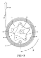
- FIG. 3 is a cross-section through the exemplary embodiment in a second operating position.
- FIG. 4 is a cross-section through the exemplary embodiment in a third operating position.
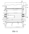
- FIG. 5 is a longitudinal section of a further exemplary embodiment.
- FIG. 1 is a longitudinal section through an exemplary embodiment of a seat belt retractor according to the present invention, illustrating the components necessary for an understanding of the invention.
- the seat belt retractor illustrated has a belt reel 1 , which is mounted rotatably in a frame 12 .
- the belt reel 1 comprises a substantially drum-shaped belt webbing carrier 4 , onto which seat belt webbing 13 may be wound and unwound.
- a blocking means 2 which may for example take the form of a catch means mounted movably on the frame 12 , allows the belt reel 1 to be blocked against rotation. To this end, the blocking means 2 engages a blockable part of the belt reel 1 .
- This blockable part may take the form of a toothed disk, or disks, arranged on one side or both sides of the belt reel 1 .
- the at least one toothed disk (blockable part 3 ) is connected non-rotatably with the belt webbing carrier 4 , for example via shearing pins (not described in any more detail) or by frictional engagement with the belt webbing carrier 4 of the belt reel 1 .
- the inside of the belt webbing carrier 4 is closed in a fluid-tight manner by end disks 14 .
- a rotor 5 is located inside the belt webbing carrier 4 .
- the rotor includes an axle 15 mounted eccentrically relative to the belt reel axis 7 , on which axle 15 a toothed inner rotor 11 is mounted rotatably eccentrically relative to the belt reel axis 7 .
- the eccentric mounted axle 15 is mounted about the belt reel axis 7 inside the belt reel 1 for example on the end disks 14 or axle journals 16 connected firmly with the blockable parts 3 , so as to be rotatable about the belt reel axis 7 .
- FIG. 2 is a cross-section through the exemplary embodiment illustrated in FIG. 1 in a first operating position.
- the rotor preferably takes the form of a toothed inner rotor 11 , as in the case of a rotor set of an internal axis rotary piston machine, wherein the teeth of the inner rotor engage the toothed outer rotor 8 .
- the outer rotor is in rotary drive connection with the belt webbing carrier and may preferably be rigidly connected therewith.
- the teeth 9 of an outer rotor 8 may move into rotary drive connection with the teeth 10 of the inner rotor 11 .
- the outer rotor 8 is in rotary drive connection with the belt webbing carrier 4 .
- the toothed outer rotor 8 is preferably connected in a torsionally rigid manner with the belt webbing carrier 4 or is formed in one piece therewith.
- the seat belt retractor according to the invention may be so constructed that the nested arrangement of belt webbing carrier, rotor and the medium filling the chambers formed has a load-limiting function or a coupling function or both.
- the in particular free-flowing medium filling the chambers preferably takes the form of a fluid of adjustable viscosity.
- An electro- and/or magneto-rheological fluid is particularly suitable for this purpose.
- chambers 6 Between the teeth 9 , 10 , which extend over the entire length of the inner chamber between the two end disks 14 of the belt reel 1 there are formed chambers 6 , which are filled with a fluid or free-flowing medium.
- the free-flowing medium preferably is a fluid of adjustable viscosity.
- the toothed inner rotor and outer rotor arrangement forms the rotor set of an internal axis rotary piston pump, in particular a gear pump of he type distributed by the Hydraulics Division of Eaton Corporation of Eden Prairie, Minn., U.S.A., sometimes referred to simply as an Eaton pump.
- a gear pump of he type distributed by the Hydraulics Division of Eaton Corporation of Eden Prairie, Minn., U.S.A., sometimes referred to simply as an Eaton pump.
- two functions may be performed, namely that of a load limiter and that of a coupling, with which a torque acting applied from outside is transmitted via the rotor 5 and the medium arranged in the chambers 6 to the belt reel carrier.
- the blockable parts (toothed disks) 3 of the belt reel 1 co-rotate during winding and unwinding of the belt webbing 13 .
- the components arranged inside the belt reel 1 also co-rotate about the belt reel axis 7 .
- the blocking means 2 engages the blockable parts 3 of the belt reel 1 .
- This engagement may take place in such a way that a drive movement generated by a tightening drive may be transmitted to the belt reel 1 .
- this engagement may take place when the belt webbing 13 has been wound onto the belt webbing carrier 4 by a tightening drive, which is not shown in any more detail in FIG. 1.
- the inner rotor 11 has a smaller number of teeth than the outer rotor 8 .
- the inner rotor 11 has four teeth and the outer rotor 8 has five teeth.
- the inner rotor 11 thus exhibits a rotational speed 5/4-times higher than that of the outer rotor 8 . Due to these different rotational speeds, the volumes of the chambers 6 formed between the teeth 9 and 10 vary, progressively in the direction of rotation, as is clear from FIGS. 2 to 4 .
- the direction of rotation in the webbing take-off direction 17 is indicated by an arrow 18 (in the clockwise direction) in FIGS. 2 to 4 .
- This rotary motion may proceed without restriction, however a limit stop for limiting the rotary motion and thus the webbing take-off length may also advantageously be reached.
- the free-flowing medium is transported out of the chambers 6 , in which the volume is reduced thereby compressing the free-flowing medium located in these chambers, into the in each case adjacent chamber increasing in volume.
- This may proceed in that the free-flowing medium is forced through the respective gap, which is formed between the teeth 9 , 10 of the outer and inner rotors, or in that additional channels are provided in the teeth 9 and/or 10 of the outer rotor 8 and the inner rotor 11 , which is shown in broken lines in FIGS. 2 to 4 .
- the overflow channels in the teeth 9 and 10 may also extend diagonally in particular in the inner rotor 11 .
- a torque may be applied from outside to the rotor 5 , in particular the axle 15 .
- This torque may be generated by an electrical drive 19 , in particular an electric motor.
- the torque is transmitted via gearing 21 to a drive shaft 20 extending through the axle journal 16 , which drive shaft 20 is preferably connected rigidly with the axle 15 .
- the drive shaft 20 extends coaxially with the belt reel axis 7 .
- FIG. 5 shows a torque introduced on one side. The torque may however also be introduced into the rotor 5 , in particular the axle 15 , on both sides.
- This torque may serve to tighten the belt webbing 13 , wherein the direction of rotation, which is transmitted to the belt webbing carrier 5 , is directed in the belt winding direction (opposite direction to the belt take-off direction 17 ).
- the viscosity of the free-flowing medium located in the chambers 6 is so adjusted that the torque is transmitted from the rotor, via the medium located in the chambers 6 to the outer rotor 8 .
- the viscosity of the medium is so adjusted that a virtually rigid connection is produced due to the greatly reduced flowability of the medium between the rotor 5 and the belt webbing carrier 4 .
- the medium located in the chambers 8 preferably takes the form of an electro- and/or magneto-rheological fluid.
- the electrical field and/or magnetic field may be caused to act on the electro- and/or magneto-rheological fluid located in the chambers 6 , preferably via the inner rotor 11 and the outer rotor 8 , which form corresponding poles by means of an externally generated electrical field or magnetic field, which is generated for example by means of an electromagnet, not described in any more detail, provided on the frame 12 .
- tightening may also be performed using a pyrotechnic or mechanical tightening drive for driving the drive shaft 20 .
- the electrical drive 19 may be used both for pretightening and for power-tightening in the event of appropriate adjustment of the viscosity of the medium located in the chambers 6 .
Landscapes
- Engineering & Computer Science (AREA)
- Mechanical Engineering (AREA)
- Automotive Seat Belt Assembly (AREA)
Abstract
Description
- The invention relates to a seat belt retractor with hydraulic load limiting.
- A known seat belt retractor comprises a belt reel for the seat belt and a blocking means for blocking rotation of a blockable part of the belt reel. The known seat belt retractor further comprises a load limiter, which consumes energy when the blocking means is activated and when the belt webbing carrier is rotated in the belt take-off direction relative to the blocked part of the belt reel. A load limiter is known from DE 199 63 580 C2 which comprises a cylinder filled with a viscous fluid, in which a piston is moved linearly with an opening comprising a variable flow cross-section as a flow path.
- There is provided in accordance with the present invention A seat belt retractor comprising a frame with a belt reel having an axis of rotation rotatably mounted in the frame, a blocking means for blocking rotation of a blockable part of the belt reel, and a substantially drum-shaped belt webbing carrier on the belt reel, wherein in the belt webbing carrier there is arranged a rotor that is in rotary drive connection with the belt webbing carrier, the belt webbing carrier drives a toothed outer rotor and the rotor comprises a toothed inner rotor, wherein chambers filled a free-flowing medium are formed by intermeshing teeth of the outer rotor and the inner rotor and upon rotation of the rotor the volumes of at least two chambers filled with the free-flowing medium are varied, wherein the chambers rotate about the belt reel axis, and in the free-flowing medium flows in each case from a chamber diminishing in volume into a chamber increasing in volume.
- FIG. 1 is a longitudinal section through an exemplary embodiment of a seat belt retractor, illustrating the components necessary for an understanding of the invention.
- FIG. 2 is a cross-section through the exemplary embodiment illustrated in FIG. 1 in a first operating position.
- FIG. 3 is a cross-section through the exemplary embodiment in a second operating position.
- FIG. 4 is a cross-section through the exemplary embodiment in a third operating position.
- FIG. 5 is a longitudinal section of a further exemplary embodiment.
- FIG. 1 is a longitudinal section through an exemplary embodiment of a seat belt retractor according to the present invention, illustrating the components necessary for an understanding of the invention. The seat belt retractor illustrated has a
belt reel 1, which is mounted rotatably in aframe 12. Thebelt reel 1 comprises a substantially drum-shapedbelt webbing carrier 4, onto whichseat belt webbing 13 may be wound and unwound. A blocking means 2, which may for example take the form of a catch means mounted movably on theframe 12, allows thebelt reel 1 to be blocked against rotation. To this end, the blocking means 2 engages a blockable part of thebelt reel 1. This blockable part may take the form of a toothed disk, or disks, arranged on one side or both sides of thebelt reel 1. In the normal operating state, the at least one toothed disk (blockable part 3) is connected non-rotatably with thebelt webbing carrier 4, for example via shearing pins (not described in any more detail) or by frictional engagement with thebelt webbing carrier 4 of thebelt reel 1. The inside of thebelt webbing carrier 4 is closed in a fluid-tight manner byend disks 14. Arotor 5 is located inside thebelt webbing carrier 4. The rotor includes anaxle 15 mounted eccentrically relative to thebelt reel axis 7, on which axle 15 a toothedinner rotor 11 is mounted rotatably eccentrically relative to thebelt reel axis 7. The eccentric mountedaxle 15 is mounted about thebelt reel axis 7 inside thebelt reel 1 for example on theend disks 14 oraxle journals 16 connected firmly with theblockable parts 3, so as to be rotatable about thebelt reel axis 7. - FIG. 2 is a cross-section through the exemplary embodiment illustrated in FIG. 1 in a first operating position. To achieve joint rotation of the
belt webbing carrier 4 and therotor 5, both in the case of the load-limiting function and in the case of torque transmission (coupling function), the rotor preferably takes the form of a toothedinner rotor 11, as in the case of a rotor set of an internal axis rotary piston machine, wherein the teeth of the inner rotor engage the toothedouter rotor 8. The outer rotor is in rotary drive connection with the belt webbing carrier and may preferably be rigidly connected therewith. Theteeth 9 of anouter rotor 8 may move into rotary drive connection with theteeth 10 of theinner rotor 11. Theouter rotor 8 is in rotary drive connection with thebelt webbing carrier 4. The toothedouter rotor 8 is preferably connected in a torsionally rigid manner with thebelt webbing carrier 4 or is formed in one piece therewith. - The seat belt retractor according to the invention may be so constructed that the nested arrangement of belt webbing carrier, rotor and the medium filling the chambers formed has a load-limiting function or a coupling function or both. The in particular free-flowing medium filling the chambers preferably takes the form of a fluid of adjustable viscosity. An electro- and/or magneto-rheological fluid is particularly suitable for this purpose. Between the
teeth end disks 14 of thebelt reel 1 there are formedchambers 6, which are filled with a fluid or free-flowing medium. The free-flowing medium preferably is a fluid of adjustable viscosity. - The toothed inner rotor and outer rotor arrangement forms the rotor set of an internal axis rotary piston pump, in particular a gear pump of he type distributed by the Hydraulics Division of Eaton Corporation of Eden Prairie, Minn., U.S.A., sometimes referred to simply as an Eaton pump. With the arrangement described, two functions may be performed, namely that of a load limiter and that of a coupling, with which a torque acting applied from outside is transmitted via the
rotor 5 and the medium arranged in thechambers 6 to the belt reel carrier. - When a motor vehicle in which the seat belt retractor is installed is traveling normally, the blockable parts (toothed disks) 3 of the
belt reel 1 co-rotate during winding and unwinding of thebelt webbing 13. The components arranged inside thebelt reel 1 also co-rotate about thebelt reel axis 7. - In the event of excessive acceleration acting on the sensor means of the seat belt retractor, for example in a crash, the blocking means 2 engages the
blockable parts 3 of thebelt reel 1. This engagement may take place in such a way that a drive movement generated by a tightening drive may be transmitted to thebelt reel 1. Moreover, this engagement may take place when thebelt webbing 13 has been wound onto thebelt webbing carrier 4 by a tightening drive, which is not shown in any more detail in FIG. 1. - If, in the event of forwards displacement of a seat-belted vehicle occupant, a force threshold is exceeded, the load-limiting function, which is integrated into the
belt reel 1, comes into effect. To this end, the non-interlocking contact fit between theblockable part 3 of thebelt reel 1 and thebelt webbing carrier 4, which is produced by shearing pins or by frictional engagement and the like during normal travel, is interrupted. When thebelt webbing 3 is taken off (the belt take-off direction is indicated by an arrow 17), thebelt webbing carrier 4 is rotated. This rotary motion is transmitted to theouter rotor 8, and theinner rotor 11 engaging with itsteeth 10 in theteeth 9 of theouter rotor 8 is co-rotated. As is clear from FIGS. 2 to 4, theinner rotor 11 has a smaller number of teeth than theouter rotor 8. In the exemplary embodiment illustrated, in which the outer rotor and inner rotor are constructed in the manner of a rotor set of an Eaton pump, theinner rotor 11 has four teeth and theouter rotor 8 has five teeth. Theinner rotor 11 thus exhibits arotational speed 5/4-times higher than that of theouter rotor 8. Due to these different rotational speeds, the volumes of thechambers 6 formed between theteeth off direction 17 is indicated by an arrow 18 (in the clockwise direction) in FIGS. 2 to 4. This rotary motion may proceed without restriction, however a limit stop for limiting the rotary motion and thus the webbing take-off length may also advantageously be reached. - During the relative rotation of the
inner rotor 11 relative to theouter rotor 8, the free-flowing medium is transported out of thechambers 6, in which the volume is reduced thereby compressing the free-flowing medium located in these chambers, into the in each case adjacent chamber increasing in volume. This may proceed in that the free-flowing medium is forced through the respective gap, which is formed between theteeth teeth 9 and/or 10 of theouter rotor 8 and theinner rotor 11, which is shown in broken lines in FIGS. 2 to 4. The overflow channels in theteeth inner rotor 11. - When the free-flowing medium is transported from one chamber to the other, energy is consumed, which effects a reduction and/or restriction of the force exerted by the seat belt webbing on the seat-belted vehicle occupant.
- In the exemplary embodiment shown in FIG. 5, a torque may be applied from outside to the
rotor 5, in particular theaxle 15. This torque may be generated by anelectrical drive 19, in particular an electric motor. The torque is transmitted viagearing 21 to adrive shaft 20 extending through theaxle journal 16, which driveshaft 20 is preferably connected rigidly with theaxle 15. Thedrive shaft 20 extends coaxially with thebelt reel axis 7. FIG. 5 shows a torque introduced on one side. The torque may however also be introduced into therotor 5, in particular theaxle 15, on both sides. This torque may serve to tighten thebelt webbing 13, wherein the direction of rotation, which is transmitted to thebelt webbing carrier 5, is directed in the belt winding direction (opposite direction to the belt take-off direction 17). To this end, the viscosity of the free-flowing medium located in thechambers 6 is so adjusted that the torque is transmitted from the rotor, via the medium located in thechambers 6 to theouter rotor 8. To this end, the viscosity of the medium is so adjusted that a virtually rigid connection is produced due to the greatly reduced flowability of the medium between therotor 5 and thebelt webbing carrier 4. - It is however also possible to adjust the load-limiting effect, which has been explained above, by means of the torque applied from outside to the rotor. At the same time, the viscosity of the medium located in the
chambers 6 may to this end be adjusted in such a way that a damped effect, additive or subtractive depending on direction of rotation, of the torque acting from outside on thebelt webbing carrier 4 is achieved. - For this purpose, the medium located in the
chambers 8 preferably takes the form of an electro- and/or magneto-rheological fluid. The electrical field and/or magnetic field may be caused to act on the electro- and/or magneto-rheological fluid located in thechambers 6, preferably via theinner rotor 11 and theouter rotor 8, which form corresponding poles by means of an externally generated electrical field or magnetic field, which is generated for example by means of an electromagnet, not described in any more detail, provided on theframe 12. Instead of the electrical drive, tightening may also be performed using a pyrotechnic or mechanical tightening drive for driving thedrive shaft 20. - The
electrical drive 19 may be used both for pretightening and for power-tightening in the event of appropriate adjustment of the viscosity of the medium located in thechambers 6. - Although the invention has been described and illustrated in detail, it is to be understood that the detail provided is by way of example and illustration, is not to be considered a limitation, and that modifications and changes therein may be made by those skilled in the art without departing from the spirit and scope of the invention. Accordingly, the scope of this invention is to be limited only by the appended claims.
Claims (21)
Applications Claiming Priority (3)
| Application Number | Priority Date | Filing Date | Title |
|---|---|---|---|
| DE10216862 | 2002-04-16 | ||
| DE10216862.8 | 2002-04-16 | ||
| DE10216862A DE10216862B4 (en) | 2002-04-16 | 2002-04-16 | Belt retractor for a vehicle seat belt |
Publications (2)
| Publication Number | Publication Date |
|---|---|
| US20030192977A1 true US20030192977A1 (en) | 2003-10-16 |
| US6695243B2 US6695243B2 (en) | 2004-02-24 |
Family
ID=28458866
Family Applications (1)
| Application Number | Title | Priority Date | Filing Date |
|---|---|---|---|
| US10/259,518 Expired - Fee Related US6695243B2 (en) | 2002-04-16 | 2002-09-30 | Seat belt retractor with hydraulic load limiting |
Country Status (3)
| Country | Link |
|---|---|
| US (1) | US6695243B2 (en) |
| DE (1) | DE10216862B4 (en) |
| FR (1) | FR2838395B1 (en) |
Cited By (8)
| Publication number | Priority date | Publication date | Assignee | Title |
|---|---|---|---|---|
| EP1529699A1 (en) * | 2003-11-07 | 2005-05-11 | Takata Corporation | Seat belt retractor |
| US20060279076A1 (en) * | 2005-06-10 | 2006-12-14 | Trw Automotive Gmbh | Force limiter for a vehicle safety belt |
| US8708370B1 (en) * | 2012-07-23 | 2014-04-29 | John Barker | Safety enhancement for a safety belt |
| CN106246861A (en) * | 2016-08-31 | 2016-12-21 | 重庆宝进机械制造有限公司 | Gear pump type based on magnetic flow liquid damping differential mechanism |
| WO2017064316A1 (en) * | 2015-10-15 | 2017-04-20 | Inventus Engineering Gmbh | Device and method for influencing the force of a seatbelt |
| EP3514022A1 (en) * | 2018-01-19 | 2019-07-24 | TRW Polska Sp.z.o.o. | Belt reel and belt retractor |
| US11725709B2 (en) * | 2016-12-12 | 2023-08-15 | Inventus Engineering Gmbh | Rotation damper with a magnetorheological fluid and damping method |
| USD1062408S1 (en) * | 2022-09-15 | 2025-02-18 | Chin-Sung Huang | Ratchet gear for a seat belt adjuster |
Families Citing this family (5)
| Publication number | Priority date | Publication date | Assignee | Title |
|---|---|---|---|---|
| DE102005036199A1 (en) * | 2005-08-02 | 2007-02-08 | Trw Automotive Gmbh | Seat belt retractor for vehicle, has rotatably supported belt reel, rotor unit arranged inside workspace, and rotation damper arranged inside belt reel, where workspace is fillable with damping medium |
| EP2045147B1 (en) * | 2007-10-03 | 2012-05-02 | Key Safety Systems, Inc. | Seat belt system for adults and children |
| US20090327052A1 (en) * | 2008-06-30 | 2009-12-31 | Wong Brian D | Interactive organizational instruction system |
| US7828331B2 (en) | 2008-07-09 | 2010-11-09 | Honda Motor Co., Ltd. | Variable load limiting device for seatbelt retractor to reduce occupant injury |
| CN107848487A (en) * | 2015-07-13 | 2018-03-27 | 关键安全体系股份有限公司 | Coiler with crushable spool insert |
Citations (2)
| Publication number | Priority date | Publication date | Assignee | Title |
|---|---|---|---|---|
| US6019392A (en) * | 1998-11-18 | 2000-02-01 | Takata, Inc. | Variable level seatbelt energy management device |
| US6241172B1 (en) * | 1996-06-26 | 2001-06-05 | Autoliv Development Ab | Belt retractor with adjustable force-limiting device |
Family Cites Families (12)
| Publication number | Priority date | Publication date | Assignee | Title |
|---|---|---|---|---|
| FR2185981A5 (en) | 1972-05-23 | 1974-01-04 | Ferodo Sa | |
| DE9308273U1 (en) | 1993-06-02 | 1993-07-29 | HS Technik und Design Technische Entwicklungen GmbH, 82234 Weßling | Device for the pyrotechnic rotary drive of a winding shaft of a safety belt retractor |
| DE4342666C2 (en) | 1993-12-14 | 1999-04-29 | Hs Tech & Design | Device for rotating a winding shaft for tightening a seat belt |
| DE19545898C2 (en) | 1995-12-08 | 1999-07-15 | Hs Tech & Design | Restraint system in a vehicle |
| GB2314755B (en) * | 1996-07-05 | 2000-08-23 | Autoliv Dev | Improvements in or relating to a safety-belt pretensioner |
| GB2330335A (en) * | 1997-10-14 | 1999-04-21 | Alliedsignal Ltd | Load limiting seat belt restraint |
| DE19902483C2 (en) * | 1999-01-22 | 2001-12-13 | Breed Automotive Tech | Seat belt retractor |
| DE19959956A1 (en) * | 1999-12-13 | 2001-06-21 | Breed Automotive Tech | Belt retractor |
| DE19963580C2 (en) * | 1999-12-29 | 2001-11-29 | Autoliv Dev | Adjustable force limiting element |
| DE10034393C2 (en) * | 2000-07-14 | 2002-07-18 | Autoliv Dev | Seat belt retractor with a fluid damper integrated in its belt shaft |
| DE10113502A1 (en) | 2001-03-20 | 2002-09-26 | Takata Petri Gmbh Ulm | Car safety belt reel has spindle with flange which locks against outer casing, nut sliding along it and forcing hydraulic fluid past edge of flange into casing if force on spindle exceeds threshold value |
| DE20215660U1 (en) * | 2002-10-11 | 2003-02-13 | TRW Occupant Restraint Systems GmbH & Co. KG, 73553 Alfdorf | Belt retractor for a vehicle seat belt |
-
2002
- 2002-04-16 DE DE10216862A patent/DE10216862B4/en not_active Expired - Fee Related
- 2002-09-30 US US10/259,518 patent/US6695243B2/en not_active Expired - Fee Related
-
2003
- 2003-04-15 FR FR0304705A patent/FR2838395B1/en not_active Expired - Fee Related
Patent Citations (2)
| Publication number | Priority date | Publication date | Assignee | Title |
|---|---|---|---|---|
| US6241172B1 (en) * | 1996-06-26 | 2001-06-05 | Autoliv Development Ab | Belt retractor with adjustable force-limiting device |
| US6019392A (en) * | 1998-11-18 | 2000-02-01 | Takata, Inc. | Variable level seatbelt energy management device |
Cited By (12)
| Publication number | Priority date | Publication date | Assignee | Title |
|---|---|---|---|---|
| EP1529699A1 (en) * | 2003-11-07 | 2005-05-11 | Takata Corporation | Seat belt retractor |
| US20050098672A1 (en) * | 2003-11-07 | 2005-05-12 | Takata Corporation | Seat belt retractor |
| US20060279076A1 (en) * | 2005-06-10 | 2006-12-14 | Trw Automotive Gmbh | Force limiter for a vehicle safety belt |
| US7651136B2 (en) * | 2005-06-10 | 2010-01-26 | Trw Automotive Gmbh | Force limiter for a vehicle safety belt |
| US8708370B1 (en) * | 2012-07-23 | 2014-04-29 | John Barker | Safety enhancement for a safety belt |
| WO2017064316A1 (en) * | 2015-10-15 | 2017-04-20 | Inventus Engineering Gmbh | Device and method for influencing the force of a seatbelt |
| US10857969B2 (en) | 2015-10-15 | 2020-12-08 | Inventus Engineering Gmbh | Device and method for influencing the force of a seatbelt |
| CN106246861A (en) * | 2016-08-31 | 2016-12-21 | 重庆宝进机械制造有限公司 | Gear pump type based on magnetic flow liquid damping differential mechanism |
| US11725709B2 (en) * | 2016-12-12 | 2023-08-15 | Inventus Engineering Gmbh | Rotation damper with a magnetorheological fluid and damping method |
| EP3514022A1 (en) * | 2018-01-19 | 2019-07-24 | TRW Polska Sp.z.o.o. | Belt reel and belt retractor |
| WO2019141721A1 (en) * | 2018-01-19 | 2019-07-25 | Trw Polska Sp.Zo.O. | Belt reel and belt retractor |
| USD1062408S1 (en) * | 2022-09-15 | 2025-02-18 | Chin-Sung Huang | Ratchet gear for a seat belt adjuster |
Also Published As
| Publication number | Publication date |
|---|---|
| DE10216862A1 (en) | 2003-11-13 |
| FR2838395B1 (en) | 2005-10-07 |
| DE10216862B4 (en) | 2005-07-07 |
| FR2838395A1 (en) | 2003-10-17 |
| US6695243B2 (en) | 2004-02-24 |
Similar Documents
| Publication | Publication Date | Title |
|---|---|---|
| US6695243B2 (en) | Seat belt retractor with hydraulic load limiting | |
| DE102008049931B4 (en) | Force limiting device for a motor vehicle | |
| US20030189331A1 (en) | Seat belt retractor with hydraulic load limiting | |
| EP1761418B1 (en) | Seat belt retractor with electric motor | |
| CN108367730B (en) | Device and method for influencing the force of a safety belt | |
| US6102439A (en) | Load limiting device for a seat belt | |
| WO2014131574A1 (en) | Rotary damper for a vehicle | |
| US7731619B2 (en) | Variable motion control device and method of use | |
| JP4814406B2 (en) | Variable load limiter for seat belt retractor to reduce occupant injury | |
| KR20010112247A (en) | Seat belt retractor | |
| US20140034432A1 (en) | Electric brake actuator for vehicles | |
| DE4412993A1 (en) | Vibration-damping device | |
| EP0188436B1 (en) | Hydraulic braking and/or locking device and inter alia use of same as differential brake and/or lock | |
| WO2009030712A2 (en) | Hydrostatic braking system | |
| EP1472116B1 (en) | Safety belt retractor with switched liquid damper | |
| EP1280684B1 (en) | Safety belt winder with a reversible belt tensioner | |
| USRE24064E (en) | Rotary pump and motor hydraulic | |
| EP3073149A1 (en) | Transmission | |
| KR102631773B1 (en) | gear shifting device | |
| KR101482860B1 (en) | Driving apparatus for side mirror | |
| JP2019214232A (en) | Steering unit for vehicle | |
| DE19643402A1 (en) | Belt tensioner of automatic safety belt unit for vehicle | |
| DE19964289B4 (en) | Seatbelt retractor has torsion bar acting as load limiting unit for drive spring which drives belt reel | |
| JP2024508431A (en) | Parallel axis friction drag brake | |
| JPH0610229Y2 (en) | Torque transmission device for four-wheel drive vehicle |
Legal Events
| Date | Code | Title | Description |
|---|---|---|---|
| AS | Assignment |
Owner name: BREED AUTOMOTIVE TECHNOLOGY, FLORIDA Free format text: ASSIGNMENT OF ASSIGNORS INTEREST;ASSIGNOR:SPECHT, MARTIN;REEL/FRAME:013351/0458 Effective date: 20020923 |
|
| AS | Assignment |
Owner name: CITICORP USA, INC. AS "ADMINISTRATOVE AGENT" AND C Free format text: SECURITY AGREEMENT;ASSIGNOR:BREED TECHNOLOGIES, INC.;REEL/FRAME:014409/0767 Effective date: 20030425 |
|
| AS | Assignment |
Owner name: KEY SAFETY SYSTEMS, INC., MICHIGAN Free format text: ASSIGNMENT OF ASSIGNORS INTEREST;ASSIGNOR:BREED AUTOMOTIVE TECHNOLOGY, INC.;REEL/FRAME:015116/0723 Effective date: 20040318 |
|
| AS | Assignment |
Owner name: CITICORP USA, INC., NEW YORK Free format text: SECURITY AGREEMENT;ASSIGNORS:KEY PLASTICS L.L.C.;KAC ACQUISITION COMPANY;KEY SAFETY SYSTEMS, INC.;AND OTHERS;REEL/FRAME:016871/0910 Effective date: 20040629 Owner name: MERRILL LYNCH CAPITAL, A DIVISION OF MERRILL LYNCH Free format text: SECURITY AGREEMENT;ASSIGNORS:KEY PLASTICS L.L.C.;KAC ACQUISITION COMPANY;KEY SAFETY SYSTEMS, INC.;AND OTHERS;REEL/FRAME:016871/0910 Effective date: 20040629 |
|
| AS | Assignment |
Owner name: CITICORP USA, INC., NEW YORK Free format text: SECURITY AGREEMENT;ASSIGNORS:KEY SAFETY SYSTEMS, INC;KSS HOLDINGS, INC;KSS ACQUISITION COMPANY;AND OTHERS;REEL/FRAME:019297/0249 Effective date: 20070308 Owner name: CITICORP USA, INC.,NEW YORK Free format text: SECURITY AGREEMENT;ASSIGNORS:KEY SAFETY SYSTEMS, INC;KSS HOLDINGS, INC;KSS ACQUISITION COMPANY;AND OTHERS;REEL/FRAME:019297/0249 Effective date: 20070308 |
|
| FPAY | Fee payment |
Year of fee payment: 4 |
|
| REMI | Maintenance fee reminder mailed | ||
| LAPS | Lapse for failure to pay maintenance fees | ||
| STCH | Information on status: patent discontinuation |
Free format text: PATENT EXPIRED DUE TO NONPAYMENT OF MAINTENANCE FEES UNDER 37 CFR 1.362 |
|
| FP | Lapsed due to failure to pay maintenance fee |
Effective date: 20120224 |