US20030192838A1 - Storage device and method of using and making same - Google Patents
Storage device and method of using and making same Download PDFInfo
- Publication number
- US20030192838A1 US20030192838A1 US10/408,008 US40800803A US2003192838A1 US 20030192838 A1 US20030192838 A1 US 20030192838A1 US 40800803 A US40800803 A US 40800803A US 2003192838 A1 US2003192838 A1 US 2003192838A1
- Authority
- US
- United States
- Prior art keywords
- storage device
- inclined surface
- elements
- generally
- support structure
- Prior art date
- Legal status (The legal status is an assumption and is not a legal conclusion. Google has not performed a legal analysis and makes no representation as to the accuracy of the status listed.)
- Granted
Links
Images


Classifications
-
- A—HUMAN NECESSITIES
- A47—FURNITURE; DOMESTIC ARTICLES OR APPLIANCES; COFFEE MILLS; SPICE MILLS; SUCTION CLEANERS IN GENERAL
- A47B—TABLES; DESKS; OFFICE FURNITURE; CABINETS; DRAWERS; GENERAL DETAILS OF FURNITURE
- A47B81/00—Cabinets or racks specially adapted for other particular purposes, e.g. for storing guns or skis
- A47B81/06—Furniture aspects of radio, television, gramophone, or record cabinets
- A47B81/068—Cassette cabinets or the like
Definitions
- the invention relates to method and system for storing elements such as media.
- the invention relates to storage devices for storing elements in a side-by-side manner.
- FIG. 1 is an elevational view of a storage device, which is constructed according to an embodiment of the invention, and which is illustrated mounted to a support structure;
- FIGS. 2 and 3 are enlarged pictorial views of the device of FIG. 1, illustrating it in its stressed bowed condition;
- FIG. 4 is a pictorial view of the device of FIG. 1, illustrating it in the unstressed flat condition
- FIG. 5 is a front elevational view of the device of FIG. 1;
- FIG. 6 is a pictorial view of the device of FIG. 1;
- FIG. 7 is an enlarged side elevational view of the device of FIG. 1;
- FIG. 8 is a pictorial view of another storage device, which is constructed according to another embodiment of the invention, and which illustrates the tope, rear and right sides thereof;
- FIG. 9 is an enlarged plan view of the device of FIG. 8;
- FIG. 10 is a pictorial view of the device of FIG. 8, illustrating the top, front and left side thereof;
- FIG. 11 is a side elevational view of the device of FIG. 8;
- FIG. 12 is a diagrammatic view of yet another storage device, which is constructed in accordance with yet another embodiment of the present invention, and which is shown mounted in a support structure;
- FIG. 13 is a diagrammatic view of still another storage device, which is constructed in accordance with still another embodiment of the present invention, and which is shown mounted in a support structure;
- FIG. 14 is a diagrammatic view of a further storage device, which is constructed in accordance with a further embodiment of the present invention, and which is shown mounted in a support structure;
- FIG. 15 is a diagrammatic view of yet a further storage device, which is constructed in accordance with yet a further embodiment of the present invention, and which is shown mounted in a support structure;
- FIG. 16 is a diagrammatic view of still a further storage device, which is constructed in accordance with still a further embodiment of the present invention, and which is shown mounted in a support structure;
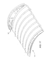
- FIG. 17 is a pictorial view of a storage device, which is constructed according to an embodiment of the invention.
- a storage device for supporting elements such as media packages, books and others, in an upright side-by-side configuration.
- the device includes a body having an inclined element support surface having a sufficient incline to cause at least one of the elements to be biased to fall under the force of gravity toward one direction and align itself against a vertical surface.
- the inclined surface may be upwardly curved in a convex manner.
- the inclined surface may be downwardly curved in a concave manner.
- the inclined surface may be a v-shaped surface having a pair of substantially flat inclined, intersecting surfaces.
- the inclined surface may be an inverted v-shaped surface. It will become apparent to those skilled in the art, that there may be compound surfaces including 2 or more of the curved or flat surfaces in accordance with the teachings relative to other embodiments of the invention.
- the disclosed embodiments of the present invention enable elements to be supported conveniently in an upright manner by merely placing them on the storage device, which may serve as a shelf mounted in a cabinet, a furniture piece, or other, or may also be free standing, without the need of a movable book end or other such side support as additional elements are placed on the storage device.
- the storage device may serve as a shelf mounted in a cabinet, a furniture piece, or other, or may also be free standing, without the need of a movable book end or other such side support as additional elements are placed on the storage device.
- additional elements are added to the storage device, they automatically fall against previously stored adjacent elements under the force or gravity to assume an upright disposition automatically without the need of placing a book end or other side support against it.
- FIGS. 1 through 7 illustrate a storage device 10 according to an embodiment of the present invention.
- the MEDIA SHELF device 10 may be adapted to be mounted onto a cabinet such as a cabinet 12 of a furniture unit (not shown). Elements such as a media package 14 may be stored on the device 10 serving as a media shelf within the cabinet or support structure 12 .
- the media elements may be books, packages such as compact disc, DVD or video packages and others.
- FIG. 1 illustrates a frontal view of the storage device 10 with an identical device 13 mounted above it for additional storage.
- the device 10 includes an inclined surface 16 on which elements may be stored in an upright side-by-side manner.
- “upright” means a generally vertical disposition.
- the surface is generally smoothly curved in an upwardly convex manner so that when the storage device 10 is mounted in a cabinet, the outside portions of the curved surface are lower than the central portion of the device. In this manner, media elements may be stored side-by-side with the bottom edges of the inner packages being higher than those of the outer packages, as illustrated clearly in FIG. 1.
- the storage device 10 may also be provided with a front lip or flange 18 and a back lip or flange 21 to support the media packages in their stored position. It is noted that either one or both lips or flanges may be omitted if no front or back support is desired. For example, if the cabinet 12 is provided with a back support, the back flange 21 may be unnecessary.
- the storage device 10 may be provided with tabs or ears 23 , 25 , 27 and 29 on each side for engaging openings (not shown) in the cabinet 12 , as an example.
- FIG. 3 illustrates two ears on each side, any appropriate number may be used.
- other suitable fastening techniques may be used, such as separate pegs, screws, separate molded parts, adhesives, or other techniques.
- a storage device such as the device 10
- the device 10 may be used to support and align elements such as media packages in a simple and clean manner.
- the curved inclined surface 16 of the media shelf 10 causes only one edge of the base of the media package to contact the curved surface 16 .
- This relationship creates a moment on the element such as a media package, causing the package to lean toward the outside of the curved inclined surface.
- an element contacts an upright surface, for example, such as an outer wall of the cabinet 12 or another support structure, the element is held steadily in its upright position.
- multiple elements such as media packages may be stored in an organized manner.
- the storage device 10 as disclosed herein is in the form of the flat blank 32 when in its unstressed condition, to enable it to be stored and shipped conveniently in a stacked configuration.
- the flanges 18 and 21 are folded upwardly in their upstanding positions, and then the body 33 of the blank 32 is flexed about its longitudinal midplane to form the configuration of FIGS. 1 through 3.
- the device 10 is retained in its stressed condition when mounted to the support structure.
- the flange 18 includes a curved edge 34 , and is attached to the body 33 by a curved living hinge 36 to permit the flange 18 to assume its upright position.
- the flange 21 includes a curved edge 38 , and includes a rectilinear transverse living hinge 41 in the blank 32 to enable the flange 21 to be folded reversely over onto itself, and then a curved living hinge 43 disposed between the living hinge 41 and the edge 38 enables the top portion of the flange 21 to be folded into an upright position as shown in FIGS. 1 - 3 and 5 - 7 .
- the flanges 18 and 21 tend to assume their upright positions in a convenient manner.
- the rear flange 21 has a curved configuration from front to rear along a longitudinal axis to assume a convex configuration when viewed from the front of the device 10 .
- This configuration helps to urge the elements in an outward orientation in the same way that the inclined surface 16 biases the elements in an outer direction.
- the rear flange can also be disposed in a rectilinear or straight configuration, or it can be curved in a concave manner as viewed from the front of the device 10 .
- FIG. 1 there can be a plurality of such storage devices employed in a support structure.
- the like storage device 13 may also be employed in a spaced-apart configuration relative to the storage device 10 .
- Each one of the storage devices can assume a generally horizontal disposition to serve as a shelf. It is to be understood that the storage devices can be inclined longitudinally relative to the front and rear portions thereof without departing from the spirit of the disclosed embodiments of the present invention.
- the elements such as media packages being stored in an upright manner can be stored in a variety of orientations. For example, if the element being stored is a book, the spine of the book can face forwardly, upwardly, or in other orientations.
- FIGS. 8 through 11 there is illustrated a storage device 45 , which is constructed according to another embodiment of the present invention, and which is similar to the device 10 except the device 45 is rigid and corrugated.
- the device 45 is provided with a curved inclined surface 47 having transverse corrugations 60 thereon.
- the transverse corrugated surface provides a stiffening effect for additional support for storing elements (not shown) on the device 45 .
- the corrugations may also extend longitudinally.
- the device 45 is also provided with a back flange or lip 49 for providing back support for the media elements.
- tabs or ears 52 , 54 , 56 and 58 are provided in pairs on each side to secure the device 45 on, for example, a furniture cabinet or other support structure.
- the corrugations include a series of peaks such as a peak 62 , alternating with a series of valleys or troughs, such as through 64 .
- the elements such as a media package 14 of FIG. 1, rests on top of the peaks such as the peak 62 .
- the apex of each peak forms a portion of the inclined surface 47 similar to the inclined surface 16 of the device 10 .
- the inclined surface 47 formed of a series of spaced apart ridges or apexes of the peaks is generally upwardly convex in configuration.
- a storage device 70 which is generally similar to the device 10 , except that it has a flat inverted v-shape.
- the device 70 may be supported in a similar manner as the device 10 , to a support structure, such as the structure having upright elements 71 and 72 by means of tabs or ears such as tabs 73 and 74 .
- the storage device 70 includes body 75 having an inverted v-shaped inclined surface 76 formed by a pair of inclined flat members 78 and 81 intersecting at an apex 83 .
- the inverted v-shared inclined surface 76 is similar to the convex inclined surface 16 of the device 10 .
- FIG. 13 there is shown a storage device 85 , which is similar to the device 10 , except that the device 85 includes a single flat surface.
- the device 85 includes pairs of tabs or ears, such as the tabs 87 and 89 for attachment to a support structure such as the support elements 90 and 91 .
- the device 85 includes a body 93 having an upper flat inclined surface 92 to serve a similar function as the inclined surface 16 of the device 10 .
- the body 93 is in the form of a generally flat panel or member.
- FIG. 14 there is disclosed a storage device 94 , which is generally similar to the device 10 , except that the device 94 is generally V-shaped.
- the device 94 has a set of tabs such as the tabs 96 and 98 which are used to attached the device 94 to a support structure, such as the support structure elements 101 and 103 .
- the device 94 includes a V-shaped inclined surface 105 of a body 106 .
- the inclined surface 105 serves a similar function as the inclined surface 16 of the device 10 .
- the body 106 includes a pair of inclined flat members 107 and 109 which intersect at an apex or bottom-most portion 112 .
- An upstanding support wall or panel 116 is disposed at the apex 112 to provide a vertical surface for elements such as media packages to be supported thereagainst on either side thereof since the side-by-side elements are biased to fall under the force of gravity inwardly toward the support wall 114 .
- FIG. 15 there is shown a storage device 116 , which is generally similar to the device 94 , except that the device 116 is smoothly curved in a concave manner.
- the device 116 includes pairs of tabs or ears, such as the tabs 118 and 119 to mount the device 116 to a support structure.
- the device 116 includes a body 120 having an upper concave inclined surface 121 , which is similar to the surface 105 .
- An upstanding support wall or panel 123 is disposed at the lower most portion of the concave body 120 to serve a similar function as the wall 114 .
- FIG. 16 there is shown a support device 125 , which is similar to the device 10 , except that the device 125 is composed of a plurality of elements or members.
- the support device 125 comprises a group of rods or wires such as the rods 126 and 127 , which are disposed in a horizontally spaced-apart manner extending between a pair of upright support structure elements at 128 and 129 .
- Each rod such as the rod 126 extends in a general horizontal disposition, but is inclined between the support structure elements 128 and 129 .
- the end of the rod 126 connected to the vertical support structure element 128 is lower than the right hand end portion of the rod 126 connected to the vertical support structure element 129 .
- the rods 126 and 127 support the elements such as media packages from below in a similar manner as the device 85 .
- the spaced-apart upper surfaces of the rods 126 and 127 form a body having an inclined surface similar to the solid one-piece body 93 of the device 85 .
- FIG. 17 there is shown a storage device 140 , which is constructed according to an embodiment of the invention, and which is similar to the device 10 , except that the rear flange is generally concave.
- the device 140 includes a series of angled steps 142 on the front face of the rear flange to cause the elements (not shown) to be driven outwardly instead of inwardly, or at least to neutralize the affect of the concave configuration.
- Such a concave configuration would tend to drive the elements inwardly, and thus the steps counter-act this tendancy.
- the storage device 45 can readily stack with like units.
- rigid embodiments of the device of the present invention such as the device 45 , can be stored and shipped in a convenient manner due to their stackable design.
- the flanges serve as stops and also serve to stiffen or rigidify the devices.
- the disclosed embodiments of the storage device according to the embodiments of the present invention may be composed of plastic, wood, paper, metal or other suitable material. Further, although certain curved and flat surfaces are illustrated in the embodiments above, it is understood that other configurations are within the scope of the present invention.
Landscapes
- Assembled Shelves (AREA)
Abstract
Description
- This application claims priority to U.S. provisional patent application entitled MEDIA SHELF AND METHOD OF USING SAME, Series No. 06/370,784, filed Apr. 6, 2002, and is incorporated herein by reference.
- The invention relates to method and system for storing elements such as media. In particular, the invention relates to storage devices for storing elements in a side-by-side manner.
- The information contained in this section relates to the background of the art of the present invention without any admission as to whether or not it legally constitutes prior art.
- Various systems of media storage are known. For example, reference may be made to the following U.S. Pat. No. 2,300,781 to Gilley, U.S. Pat. No. 3,472,386 to Osojnak, U.S. Pat. No. 3,554,381 to Guest et al., U.S. Pat. No. 3,889,812 to Gutierrez, U.S. Pat. No. 3,966,050 to Dahl, U.S. Pat. No. 4,312,548 to Posso, U.S. Pat. No. 4,819,813 to Schubert, U.S. Pat. No. 5,027,955 to Shoemaker, U.S. Pat. No. 5,381,908 to Hepp, U.S. Pat. No. 5,558,235 to Hunt, U.S. Pat. No. 5,794,796 to Weisburn, and U.S. Pat. No. 5,823,332 to Clausen.
- The following is a description of the drawings of certain embodiments of the present invention:
- FIG. 1 is an elevational view of a storage device, which is constructed according to an embodiment of the invention, and which is illustrated mounted to a support structure;
- FIGS. 2 and 3 are enlarged pictorial views of the device of FIG. 1, illustrating it in its stressed bowed condition;
- FIG. 4 is a pictorial view of the device of FIG. 1, illustrating it in the unstressed flat condition;
- FIG. 5 is a front elevational view of the device of FIG. 1;
- FIG. 6 is a pictorial view of the device of FIG. 1;
- FIG. 7 is an enlarged side elevational view of the device of FIG. 1;
- FIG. 8 is a pictorial view of another storage device, which is constructed according to another embodiment of the invention, and which illustrates the tope, rear and right sides thereof;
- FIG. 9 is an enlarged plan view of the device of FIG. 8;
- FIG. 10 is a pictorial view of the device of FIG. 8, illustrating the top, front and left side thereof;
- FIG. 11 is a side elevational view of the device of FIG. 8;
- FIG. 12 is a diagrammatic view of yet another storage device, which is constructed in accordance with yet another embodiment of the present invention, and which is shown mounted in a support structure;
- FIG. 13 is a diagrammatic view of still another storage device, which is constructed in accordance with still another embodiment of the present invention, and which is shown mounted in a support structure;
- FIG. 14 is a diagrammatic view of a further storage device, which is constructed in accordance with a further embodiment of the present invention, and which is shown mounted in a support structure;
- FIG. 15 is a diagrammatic view of yet a further storage device, which is constructed in accordance with yet a further embodiment of the present invention, and which is shown mounted in a support structure;
- FIG. 16 is a diagrammatic view of still a further storage device, which is constructed in accordance with still a further embodiment of the present invention, and which is shown mounted in a support structure; and
- FIG. 17 is a pictorial view of a storage device, which is constructed according to an embodiment of the invention.
- According to the disclosed embodiments of the present invention, there is provided a storage device for supporting elements such as media packages, books and others, in an upright side-by-side configuration. The device includes a body having an inclined element support surface having a sufficient incline to cause at least one of the elements to be biased to fall under the force of gravity toward one direction and align itself against a vertical surface.
- According to one of the embodiments of the invention, the inclined surface may be upwardly curved in a convex manner. Alternatively, according to another embodiment of the invention, the inclined surface may be downwardly curved in a concave manner. According to another embodiment of the invention, the inclined surface may be a v-shaped surface having a pair of substantially flat inclined, intersecting surfaces. According to a still further embodiment, the inclined surface may be an inverted v-shaped surface. It will become apparent to those skilled in the art, that there may be compound surfaces including 2 or more of the curved or flat surfaces in accordance with the teachings relative to other embodiments of the invention.
- Thus, the disclosed embodiments of the present invention enable elements to be supported conveniently in an upright manner by merely placing them on the storage device, which may serve as a shelf mounted in a cabinet, a furniture piece, or other, or may also be free standing, without the need of a movable book end or other such side support as additional elements are placed on the storage device. In this regard, as additional elements are added to the storage device, they automatically fall against previously stored adjacent elements under the force or gravity to assume an upright disposition automatically without the need of placing a book end or other side support against it.
- Referring now to the drawings, FIGS. 1 through 7 illustrate a
storage device 10 according to an embodiment of the present invention. The MEDIA SHELFdevice 10 may be adapted to be mounted onto a cabinet such as acabinet 12 of a furniture unit (not shown). Elements such as amedia package 14 may be stored on thedevice 10 serving as a media shelf within the cabinet orsupport structure 12. The media elements may be books, packages such as compact disc, DVD or video packages and others. FIG. 1 illustrates a frontal view of thestorage device 10 with anidentical device 13 mounted above it for additional storage. - The
device 10 includes aninclined surface 16 on which elements may be stored in an upright side-by-side manner. As used herein, “upright” means a generally vertical disposition. As illustrated in FIG. 1, the surface is generally smoothly curved in an upwardly convex manner so that when thestorage device 10 is mounted in a cabinet, the outside portions of the curved surface are lower than the central portion of the device. In this manner, media elements may be stored side-by-side with the bottom edges of the inner packages being higher than those of the outer packages, as illustrated clearly in FIG. 1. - The
storage device 10 may also be provided with a front lip orflange 18 and a back lip orflange 21 to support the media packages in their stored position. It is noted that either one or both lips or flanges may be omitted if no front or back support is desired. For example, if thecabinet 12 is provided with a back support, theback flange 21 may be unnecessary. - As most clearly illustrated in FIG. 3, the
storage device 10 may be provided with tabs orears cabinet 12, as an example. Although FIG. 3 illustrates two ears on each side, any appropriate number may be used. For example, it will become apparent to those skilled in the art that only one may be used. Also, other suitable fastening techniques may be used, such as separate pegs, screws, separate molded parts, adhesives, or other techniques. - Thus, a storage device according to the embodiments of the invention, such as the
device 10, may be used to support and align elements such as media packages in a simple and clean manner. The curvedinclined surface 16 of themedia shelf 10 causes only one edge of the base of the media package to contact thecurved surface 16. This relationship creates a moment on the element such as a media package, causing the package to lean toward the outside of the curved inclined surface. When an element contacts an upright surface, for example, such as an outer wall of thecabinet 12 or another support structure, the element is held steadily in its upright position. Thus, multiple elements such as media packages may be stored in an organized manner. - The
storage device 10 as disclosed herein, is in the form of the flat blank 32 when in its unstressed condition, to enable it to be stored and shipped conveniently in a stacked configuration. In order to assume the configuration as shown in FIGS. 1 through 3, theflanges body 33 of the blank 32 is flexed about its longitudinal midplane to form the configuration of FIGS. 1 through 3. Thedevice 10 is retained in its stressed condition when mounted to the support structure. - Considering now, the
flange 18 in greater detail, theflange 18 includes acurved edge 34, and is attached to thebody 33 by acurved living hinge 36 to permit theflange 18 to assume its upright position. - Considering the
flange 21 in greater detail, theflange 21 includes acurved edge 38, and includes a rectilineartransverse living hinge 41 in the blank 32 to enable theflange 21 to be folded reversely over onto itself, and then acurved living hinge 43 disposed between the livinghinge 41 and theedge 38 enables the top portion of theflange 21 to be folded into an upright position as shown in FIGS. 1-3 and 5-7. As thebody 33 of the blank 32 is flexed about its longitudinal midplane, theflanges - As best seen in FIGS. 2 and 7, the
rear flange 21 has a curved configuration from front to rear along a longitudinal axis to assume a convex configuration when viewed from the front of thedevice 10. This configuration helps to urge the elements in an outward orientation in the same way that theinclined surface 16 biases the elements in an outer direction. It will be understood to those skilled in the art that the rear flange can also be disposed in a rectilinear or straight configuration, or it can be curved in a concave manner as viewed from the front of thedevice 10. - As shown in FIG. 1, there can be a plurality of such storage devices employed in a support structure. For example, the
like storage device 13 may also be employed in a spaced-apart configuration relative to thestorage device 10. Each one of the storage devices can assume a generally horizontal disposition to serve as a shelf. It is to be understood that the storage devices can be inclined longitudinally relative to the front and rear portions thereof without departing from the spirit of the disclosed embodiments of the present invention. Additionally, it is to be understood that the elements such as media packages being stored in an upright manner can be stored in a variety of orientations. For example, if the element being stored is a book, the spine of the book can face forwardly, upwardly, or in other orientations. - In order to help the blank 32 to flex about its midplane, there can be additional living hinges extending longitudinally along the
body 33 to help it to flex. Additionally, living hinges may be provided at the connecting point of the tabs to thebody 33. - Referring now to FIGS. 8 through 11, there is illustrated a
storage device 45, which is constructed according to another embodiment of the present invention, and which is similar to thedevice 10 except thedevice 45 is rigid and corrugated. Thedevice 45 is provided with a curvedinclined surface 47 havingtransverse corrugations 60 thereon. The transverse corrugated surface provides a stiffening effect for additional support for storing elements (not shown) on thedevice 45. It is to be understood that the corrugations may also extend longitudinally. Thedevice 45 is also provided with a back flange orlip 49 for providing back support for the media elements. Further, tabs orears device 45 on, for example, a furniture cabinet or other support structure. - The corrugations include a series of peaks such as a
peak 62, alternating with a series of valleys or troughs, such as through 64. The elements such as amedia package 14 of FIG. 1, rests on top of the peaks such as thepeak 62. Thus, the apex of each peak forms a portion of theinclined surface 47 similar to theinclined surface 16 of thedevice 10. In this regard, theinclined surface 47 formed of a series of spaced apart ridges or apexes of the peaks, is generally upwardly convex in configuration. - Referring now to FIG. 12, there is shown a
storage device 70, which is generally similar to thedevice 10, except that it has a flat inverted v-shape. Thedevice 70 may be supported in a similar manner as thedevice 10, to a support structure, such as the structure havingupright elements tabs storage device 70 includesbody 75 having an inverted v-shapedinclined surface 76 formed by a pair of inclinedflat members inclined surface 76 is similar to the convexinclined surface 16 of thedevice 10. - Referring now to FIG. 13, there is shown a
storage device 85, which is similar to thedevice 10, except that thedevice 85 includes a single flat surface. Thedevice 85 includes pairs of tabs or ears, such as thetabs support elements - The
device 85 includes abody 93 having an upper flatinclined surface 92 to serve a similar function as theinclined surface 16 of thedevice 10. In this regard, thebody 93 is in the form of a generally flat panel or member. - Referring now to FIG. 14, there is disclosed a
storage device 94, which is generally similar to thedevice 10, except that thedevice 94 is generally V-shaped. Thedevice 94 has a set of tabs such as thetabs device 94 to a support structure, such as thesupport structure elements - The
device 94 includes a V-shapedinclined surface 105 of abody 106. Theinclined surface 105 serves a similar function as theinclined surface 16 of thedevice 10. - The
body 106 includes a pair of inclinedflat members bottom-most portion 112. An upstanding support wall orpanel 116 is disposed at the apex 112 to provide a vertical surface for elements such as media packages to be supported thereagainst on either side thereof since the side-by-side elements are biased to fall under the force of gravity inwardly toward thesupport wall 114. - Referring now to FIG. 15, there is shown a
storage device 116, which is generally similar to thedevice 94, except that thedevice 116 is smoothly curved in a concave manner. Thedevice 116 includes pairs of tabs or ears, such as thetabs device 116 to a support structure. Thedevice 116 includes abody 120 having an upper concaveinclined surface 121, which is similar to thesurface 105. An upstanding support wall orpanel 123 is disposed at the lower most portion of theconcave body 120 to serve a similar function as thewall 114. - Referring now to FIG. 16, there is shown a
support device 125, which is similar to thedevice 10, except that thedevice 125 is composed of a plurality of elements or members. Thesupport device 125 comprises a group of rods or wires such as therods rod 126 extends in a general horizontal disposition, but is inclined between thesupport structure elements rod 126 connected to the verticalsupport structure element 128 is lower than the right hand end portion of therod 126 connected to the verticalsupport structure element 129. Thus, therods device 85. The spaced-apart upper surfaces of therods piece body 93 of thedevice 85. - Referring now to FIG. 17, there is shown a
storage device 140, which is constructed according to an embodiment of the invention, and which is similar to thedevice 10, except that the rear flange is generally concave. Thedevice 140 includes a series ofangled steps 142 on the front face of the rear flange to cause the elements (not shown) to be driven outwardly instead of inwardly, or at least to neutralize the affect of the concave configuration. Such a concave configuration would tend to drive the elements inwardly, and thus the steps counter-act this tendancy. - It should be understood that various ones of the storage devices disclosed herein may be stacked or nested. For example, the
storage device 45 can readily stack with like units. In this regard, rigid embodiments of the device of the present invention such as thedevice 45, can be stored and shipped in a convenient manner due to their stackable design. - With the storage devices disclosed herein having upstanding flanges, the flanges serve as stops and also serve to stiffen or rigidify the devices.
- It is understood that the disclosed embodiments of the storage device according to the embodiments of the present invention may be composed of plastic, wood, paper, metal or other suitable material. Further, although certain curved and flat surfaces are illustrated in the embodiments above, it is understood that other configurations are within the scope of the present invention.
- While particular embodiments of the present invention have been disclosed, it is to be understood that various different modifications and combinations are possible and are contemplated within the true spirit and scope of the invention. There is no intention, therefore, of limitations to the exact disclosure herein presented.
Claims (24)
Priority Applications (1)
| Application Number | Priority Date | Filing Date | Title |
|---|---|---|---|
| US10/408,008 US6994222B2 (en) | 2002-04-06 | 2003-04-04 | Storage device and method of using and making same |
Applications Claiming Priority (2)
| Application Number | Priority Date | Filing Date | Title |
|---|---|---|---|
| US37078402P | 2002-04-06 | 2002-04-06 | |
| US10/408,008 US6994222B2 (en) | 2002-04-06 | 2003-04-04 | Storage device and method of using and making same |
Publications (2)
| Publication Number | Publication Date |
|---|---|
| US20030192838A1 true US20030192838A1 (en) | 2003-10-16 |
| US6994222B2 US6994222B2 (en) | 2006-02-07 |
Family
ID=28794390
Family Applications (1)
| Application Number | Title | Priority Date | Filing Date |
|---|---|---|---|
| US10/408,008 Expired - Fee Related US6994222B2 (en) | 2002-04-06 | 2003-04-04 | Storage device and method of using and making same |
Country Status (1)
| Country | Link |
|---|---|
| US (1) | US6994222B2 (en) |
Families Citing this family (8)
| Publication number | Priority date | Publication date | Assignee | Title |
|---|---|---|---|---|
| US7448502B2 (en) * | 2005-01-14 | 2008-11-11 | Spectrum Concepts, Inc. | Media storage organizer and method for using same |
| US8276769B2 (en) * | 2008-07-03 | 2012-10-02 | Hogeback Woodworking, Inc. | Wine rack |
| USD775500S1 (en) | 2015-06-29 | 2017-01-03 | Darryl Hogeback | Circular wine rack |
| US10405657B2 (en) * | 2017-05-17 | 2019-09-10 | Knoll, Inc. | Bracket mechanism for pre-fabricated office enclosure beams and method of using the same |
| US11346382B2 (en) | 2017-08-30 | 2022-05-31 | Clark Evan Davis | Modular furniture with stressed dovetail tab joint |
| US11154137B2 (en) * | 2017-08-30 | 2021-10-26 | Clark Evan Davis | Modular furniture with locking tab and slot joint |
| US11578739B2 (en) | 2017-10-05 | 2023-02-14 | Clark Davis | Furniture with interwoven tab and slot joint |
| US11767867B2 (en) | 2020-11-17 | 2023-09-26 | Clark Davis | Pivoting joint for wooden furniture |
Citations (28)
| Publication number | Priority date | Publication date | Assignee | Title |
|---|---|---|---|---|
| US2300781A (en) * | 1941-11-24 | 1942-11-03 | Robert H Gilley | Sheet work support |
| US2499220A (en) * | 1946-04-09 | 1950-02-28 | Clare L Hinsdale | Rack for phonograph records |
| US3472386A (en) * | 1967-05-03 | 1969-10-14 | Engineered Data Products Inc | Reel storage apparatus |
| US3554381A (en) * | 1968-07-26 | 1971-01-12 | Jack B Guest | Document sorting device |
| US3603460A (en) * | 1969-09-15 | 1971-09-07 | Lyle W Roeder | Apparatus for storing phonograph records |
| US3868018A (en) * | 1972-10-27 | 1975-02-25 | Xytex Corp | Tape reel cartridge storage cell |
| US3889812A (en) * | 1974-05-24 | 1975-06-17 | Julian Gutierrez | Phonograph record tilting display apparatus |
| US3966050A (en) * | 1975-03-31 | 1976-06-29 | Dahl Robert M | Index file |
| US4312548A (en) * | 1979-05-14 | 1982-01-26 | Patrick Posso | Drawer unit for storing cases normally containing magnetic tape cassettes |
| US4715669A (en) * | 1986-06-27 | 1987-12-29 | Russ Bassett Company | Cartridge cabinet drawer |
| US4819813A (en) * | 1984-11-27 | 1989-04-11 | Lift Verkaufsgerate-Gesellschaft M.B.H. | Device for holding objects and arrangement provided with such devices |
| US5027955A (en) * | 1989-12-19 | 1991-07-02 | Shoemaker Stephen P Jr | Storage rack for discs, cassettes and the like |
| USRE34217E (en) * | 1990-01-23 | 1993-04-13 | Modular rack unit | |
| US5381908A (en) * | 1993-09-20 | 1995-01-17 | All Stock Displays Inc. | Organizer for grocery shelves |
| US5415298A (en) * | 1993-11-30 | 1995-05-16 | Microplas, Inc. | Recorded medium storage case |
| US5558235A (en) * | 1994-09-06 | 1996-09-24 | Spectrum Concepts, Inc. | Organizer support structure for audio/video media |
| US5632374A (en) * | 1995-12-07 | 1997-05-27 | Microplas, Inc. | Compact disc transfer station |
| US5740924A (en) * | 1996-09-10 | 1998-04-21 | Spectrum Concepts, Inc. | Organizer rack component and method of using same |
| US5791748A (en) * | 1996-10-29 | 1998-08-11 | Computer Expressions Incorporated | Compact disc holder |
| US5794796A (en) * | 1994-12-20 | 1998-08-18 | Alpha Enterprises, Inc. | Storage rack for retaining software devices having multiple configurations |
| US5823332A (en) * | 1995-11-13 | 1998-10-20 | Allsop, Inc. | Multimedia storage device |
| US6082553A (en) * | 1997-10-30 | 2000-07-04 | Stravitz; David M. | Stepped organizer/rack |
| US6279757B1 (en) * | 1997-02-12 | 2001-08-28 | Ari Maurice Hayoun | System and a support and storing device for CD's |
| US6308839B1 (en) * | 1999-10-21 | 2001-10-30 | Richard Steinberg | Media storage rack |
| US6626301B2 (en) * | 2001-06-27 | 2003-09-30 | De Rouvray John Alexander | Compact disk holder |
| US20030192837A1 (en) * | 2002-04-12 | 2003-10-16 | Spectrum Concepts, Inc. | Storage tray and method of using same |
| US6648150B2 (en) * | 2000-08-01 | 2003-11-18 | The Cd Storage Company Limited | Storage device |
| US6758346B2 (en) * | 2001-03-27 | 2004-07-06 | Disc Dealer, Inc. | Apparatus for storing disks |
-
2003
- 2003-04-04 US US10/408,008 patent/US6994222B2/en not_active Expired - Fee Related
Patent Citations (28)
| Publication number | Priority date | Publication date | Assignee | Title |
|---|---|---|---|---|
| US2300781A (en) * | 1941-11-24 | 1942-11-03 | Robert H Gilley | Sheet work support |
| US2499220A (en) * | 1946-04-09 | 1950-02-28 | Clare L Hinsdale | Rack for phonograph records |
| US3472386A (en) * | 1967-05-03 | 1969-10-14 | Engineered Data Products Inc | Reel storage apparatus |
| US3554381A (en) * | 1968-07-26 | 1971-01-12 | Jack B Guest | Document sorting device |
| US3603460A (en) * | 1969-09-15 | 1971-09-07 | Lyle W Roeder | Apparatus for storing phonograph records |
| US3868018A (en) * | 1972-10-27 | 1975-02-25 | Xytex Corp | Tape reel cartridge storage cell |
| US3889812A (en) * | 1974-05-24 | 1975-06-17 | Julian Gutierrez | Phonograph record tilting display apparatus |
| US3966050A (en) * | 1975-03-31 | 1976-06-29 | Dahl Robert M | Index file |
| US4312548A (en) * | 1979-05-14 | 1982-01-26 | Patrick Posso | Drawer unit for storing cases normally containing magnetic tape cassettes |
| US4819813A (en) * | 1984-11-27 | 1989-04-11 | Lift Verkaufsgerate-Gesellschaft M.B.H. | Device for holding objects and arrangement provided with such devices |
| US4715669A (en) * | 1986-06-27 | 1987-12-29 | Russ Bassett Company | Cartridge cabinet drawer |
| US5027955A (en) * | 1989-12-19 | 1991-07-02 | Shoemaker Stephen P Jr | Storage rack for discs, cassettes and the like |
| USRE34217E (en) * | 1990-01-23 | 1993-04-13 | Modular rack unit | |
| US5381908A (en) * | 1993-09-20 | 1995-01-17 | All Stock Displays Inc. | Organizer for grocery shelves |
| US5415298A (en) * | 1993-11-30 | 1995-05-16 | Microplas, Inc. | Recorded medium storage case |
| US5558235A (en) * | 1994-09-06 | 1996-09-24 | Spectrum Concepts, Inc. | Organizer support structure for audio/video media |
| US5794796A (en) * | 1994-12-20 | 1998-08-18 | Alpha Enterprises, Inc. | Storage rack for retaining software devices having multiple configurations |
| US5823332A (en) * | 1995-11-13 | 1998-10-20 | Allsop, Inc. | Multimedia storage device |
| US5632374A (en) * | 1995-12-07 | 1997-05-27 | Microplas, Inc. | Compact disc transfer station |
| US5740924A (en) * | 1996-09-10 | 1998-04-21 | Spectrum Concepts, Inc. | Organizer rack component and method of using same |
| US5791748A (en) * | 1996-10-29 | 1998-08-11 | Computer Expressions Incorporated | Compact disc holder |
| US6279757B1 (en) * | 1997-02-12 | 2001-08-28 | Ari Maurice Hayoun | System and a support and storing device for CD's |
| US6082553A (en) * | 1997-10-30 | 2000-07-04 | Stravitz; David M. | Stepped organizer/rack |
| US6308839B1 (en) * | 1999-10-21 | 2001-10-30 | Richard Steinberg | Media storage rack |
| US6648150B2 (en) * | 2000-08-01 | 2003-11-18 | The Cd Storage Company Limited | Storage device |
| US6758346B2 (en) * | 2001-03-27 | 2004-07-06 | Disc Dealer, Inc. | Apparatus for storing disks |
| US6626301B2 (en) * | 2001-06-27 | 2003-09-30 | De Rouvray John Alexander | Compact disk holder |
| US20030192837A1 (en) * | 2002-04-12 | 2003-10-16 | Spectrum Concepts, Inc. | Storage tray and method of using same |
Also Published As
| Publication number | Publication date |
|---|---|
| US6994222B2 (en) | 2006-02-07 |
Similar Documents
| Publication | Publication Date | Title |
|---|---|---|
| US5314077A (en) | Storage rack | |
| AU667598B2 (en) | Storage rack | |
| US7140705B2 (en) | Infinitely adjustable module row divider for a cabinet drawer | |
| US5595312A (en) | Easily assembled and adjustable storage and display tower assembly | |
| US5174539A (en) | Reversible mounting bracket for electronic devices | |
| US5346078A (en) | Display shelf assembly | |
| US5423434A (en) | Adjustable disk show rack | |
| US6994222B2 (en) | Storage device and method of using and making same | |
| US7185767B2 (en) | Desk Organizer | |
| EP0988989A2 (en) | A sheet stand | |
| US6364129B1 (en) | Adjustable multimedia storage rack | |
| EP2036739A1 (en) | Document sorting apparatus with multiple-position wire divider members | |
| US5860535A (en) | Shelf restraint | |
| EP0368502B1 (en) | Rotatable articulated merchandise display unit | |
| EP0995194A1 (en) | A SYSTEM AND A SUPPORT AND STORING DEVICE FOR CD's | |
| US6010015A (en) | Decorative compact disk rack | |
| CA2484811C (en) | Storage device and method of using and making same | |
| US5787818A (en) | Method of placing a shelf in a storage compartment | |
| US6457689B1 (en) | Sign support having offset pivot | |
| US6050425A (en) | Storage rack for recording media | |
| US5676262A (en) | Bakeware storage and dispensing system | |
| WO1995020222A1 (en) | A holder for flat articles and a wall mounting device for use in connection with such a holder | |
| EP0113929A1 (en) | Merchandise display device | |
| JP3029486U (en) | Parts of storage containers such as paper | |
| US4756441A (en) | File system support assembly |
Legal Events
| Date | Code | Title | Description |
|---|---|---|---|
| AS | Assignment |
Owner name: SPECTRUM CONCEPTS, INC., CALIFORNIA Free format text: ASSIGNMENT OF ASSIGNORS INTEREST;ASSIGNOR:HUNT, THOMAS A.;REEL/FRAME:014440/0221 Effective date: 20030424 |
|
| AS | Assignment |
Owner name: SPECTRUM CONCEPTS, INC., CALIFORNIA Free format text: ASSIGNMENT OF ASSIGNORS INTEREST;ASSIGNOR:HUNT, THOMAS;REEL/FRAME:014623/0287 Effective date: 20040503 |
|
| FEPP | Fee payment procedure |
Free format text: PAYER NUMBER DE-ASSIGNED (ORIGINAL EVENT CODE: RMPN); ENTITY STATUS OF PATENT OWNER: SMALL ENTITY Free format text: PAYOR NUMBER ASSIGNED (ORIGINAL EVENT CODE: ASPN); ENTITY STATUS OF PATENT OWNER: SMALL ENTITY |
|
| CC | Certificate of correction | ||
| FPAY | Fee payment |
Year of fee payment: 4 |
|
| REMI | Maintenance fee reminder mailed | ||
| LAPS | Lapse for failure to pay maintenance fees | ||
| STCH | Information on status: patent discontinuation |
Free format text: PATENT EXPIRED DUE TO NONPAYMENT OF MAINTENANCE FEES UNDER 37 CFR 1.362 |
|
| STCH | Information on status: patent discontinuation |
Free format text: PATENT EXPIRED DUE TO NONPAYMENT OF MAINTENANCE FEES UNDER 37 CFR 1.362 |
|
| FP | Lapsed due to failure to pay maintenance fee |
Effective date: 20140207 |