US20030192837A1 - Storage tray and method of using same - Google Patents
Storage tray and method of using same Download PDFInfo
- Publication number
- US20030192837A1 US20030192837A1 US10/121,979 US12197902A US2003192837A1 US 20030192837 A1 US20030192837 A1 US 20030192837A1 US 12197902 A US12197902 A US 12197902A US 2003192837 A1 US2003192837 A1 US 2003192837A1
- Authority
- US
- United States
- Prior art keywords
- item
- support
- storage device
- item storage
- perimeter edge
- Prior art date
- Legal status (The legal status is an assumption and is not a legal conclusion. Google has not performed a legal analysis and makes no representation as to the accuracy of the status listed.)
- Granted
Links
Images


Classifications
-
- G—PHYSICS
- G11—INFORMATION STORAGE
- G11B—INFORMATION STORAGE BASED ON RELATIVE MOVEMENT BETWEEN RECORD CARRIER AND TRANSDUCER
- G11B33/00—Constructional parts, details or accessories not provided for in the other groups of this subclass
- G11B33/02—Cabinets; Cases; Stands; Disposition of apparatus therein or thereon
- G11B33/04—Cabinets; Cases; Stands; Disposition of apparatus therein or thereon modified to store record carriers
- G11B33/0405—Cabinets; Cases; Stands; Disposition of apparatus therein or thereon modified to store record carriers for storing discs
- G11B33/0461—Disc storage racks
Definitions
- the invention relates to method and system for storing items.
- the invention relates to storage trays adapted to render items readily accessible.
- Such organizers and storage devices typically would only store one type of such multimedia package, such as a compact disk package.
- One successful device for storing different kinds of multimedia packages at the same time is disclosed in U.S. Pat. No. 5,558,235, which is incorporated herein by reference.
- the patented device stores a series of different types and kinds of multimedia packages in a closely spaced upright stack configuration in a side-by-side manner by utilizing individual compartments. Each one of the packages can be flipped between forwardly and rearwardly inclined positions to inspect the different packages and for aiding in the selection of a given one of them.
- FIG. 1 is a pictorial diagram of a storage tray according to an embodiment of the invention.
- FIG. 2 is a cross-sectional side view of the storage tray of FIG. 1 with items in a stored position;
- FIG. 3 is a cross-sectional side view of the storage tray of FIG. 1 with one item in an ejected position;
- FIG. 4 is a cross-sectional side view of a storage tray according to another embodiment of the invention with an item in a stored position;
- FIG. 5 is a cross-sectional side view of the storage tray of FIG. 4 with an item in an ejected position
- FIG. 6 is a pictorial diagram of a storage tray according to a further embodiment of the invention.
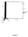
- FIG. 7 is a cross-sectional side view of the storage tray of FIG. 6 with an item in a stored position
- FIG. 8 is a cross-sectional side view of the storage tray of FIG. 6 with an item in an ejected position
- FIG. 9 is a cross-sectional side view of a storage tray according to a still further embodiment of the invention with an item in a stored position;
- FIG. 10 is a cross-sectional side view of the storage tray of FIG. 9 with an item in an ejected position;
- FIG. 11 is a cross-sectional side view of a storage tray according to yet another embodiment of the invention with an item in a stored position;
- FIG. 12 is a cross-sectional side view of the storage tray of FIG. 11 with an item in an ejected position;
- FIG. 13 is a cross-sectional side view of a storage tray according to yet a further embodiment of the invention with an item in a stored position;
- FIG. 14 is a cross-sectional side view of the storage tray of FIG. 13 with an item in an ejected position
- FIG. 15 is a pictorial diagram of a storage tray according to yet another embodiment of the invention.
- FIG. 16 is a cross-sectional side view of the storage tray of FIG. 15 with an item in a stored position
- FIG. 17 is a cross-sectional side view of the storage tray of FIG. 15 with an item in a transition state
- FIG. 18 is a cross-sectional side view of the storage tray of FIG. 15 with an item in an ejected position;
- FIG. 19 is a pictorial diagram of a storage tray according to a still further embodiment of the invention.
- FIG. 20 is a cross-sectional side view of the storage tray of FIG. 19 with an item in a stored position
- FIG. 21 is a cross-sectional side view of the storage tray of FIG. 19 with an item in a transition state
- FIG. 22 is a cross-sectional side view of the storage tray of FIG. 19 with an item in an ejected position;
- FIG. 23 is a pictorial diagram of a storage tray according to yet a further embodiment of the invention.
- FIG. 24 is a cross-sectional side view of the storage tray of FIG. 23 with an item in a stored position
- FIG. 25 is a cross-sectional side view of the storage tray of FIG. 23 with an item in an ejected position;
- FIG. 26 is a pictorial diagram of a storage tray according to still another embodiment of the invention.
- FIG. 27 is a cross-sectional side view of the storage tray of FIG. 26 with an item in a stored position
- FIG. 28 is a cross-sectional side view of the storage tray of FIG. 26 with an item in an ejected position.
- the present invention provides a system and a method for storage of items such as media packages and others.
- the disclosed embodiments of the invention enables the easy removal of a desired one item from a plurality of closely spaced stored items.
- the disclosed embodiments are adapted to support an item such as a multimedia package in at least two positions, a stored position and an ejected position.
- an item may be aligned with adjacent items to allow a user to view a perimeter edge of each item.
- a latch support secures the item in the stored position, and allows the unlatching of the item to permit it to rotate and /or translate under force of gravity to a stable ejected position.
- a portion of the desired item protrudes from the alignment, allowing a user to easily grasp and remove the desired item without disturbing adjacent items.
- FIGS. 1 through 3 illustrate one embodiment of a storage tray 10 according to the present invention.
- the tray 10 may be supported between a pair of parallel, spaced-apart upright walls, such as a wall 11 of a furniture unit such as a desk, the opposite wall not being illustrated for sake of clarity. It is to be understood that there may be different types and kinds of supports for the tray 10 .
- the storage tray includes a tray body 12 adapted to store items such as a CD package 13 .
- the tray body 12 comprises an upper arc 14 and a lower arc 16 converging at a front rail 18 and a rear rail 21 .
- the front rail 18 and the rear rail 21 are provided with front pegs 23 and 24 , and rear pegs such as rear peg 25 , respectively, at each end of the tray body.
- the front and rear pegs may be used to secure the storage tray to, for example, the walls such as the wall 11 of the unit of office furniture.
- the pegs such as the peg 24 is adapted to fit into an opening or hole (not shown) in the wall 11 .
- the upper arc 14 and the lower arc 16 may be in a flat configuration for transportation purposes.
- the pegs 23 - 25 may be used to secure the tray body 12 to a furniture piece in a deformed or stressed configuration in which the upper arc and the lower arc are deformed under pressure into the position illustrated in FIG. 1 due to the spacing of the holes (not shown) in the support structure.
- the tray of the present invention may also be configured in other ways, such, for example, as a fixed or non-deformable version of the tray 10 .
- the upper arc 14 is provided with a plurality of top flanges 27 forming top slots or openings 29 therebetween.
- the lower arc 16 is provided with a series of bottom flanges 32 forming bottom slots or openings 34 .
- the top flanges 27 and the bottom flanges 32 are positions such that each top slot 29 has a corresponding bottom slot 34 .
- the slots 29 , 34 are sized to accommodate a variety of items. For example, the slots are large enough to hold a DVD package, as well as thinner CD packages.
- An angled slot edge 36 may be provided at the front end of the slots for securing thinner packages such as CD package 13 in a relatively wider slot. The angled slot edge 36 prevents side to side movement of the thinner package. Additional angled slot edges may be provided at the back end for further securing.
- FIG. 2 illustrates a cross sectional side view of the storage tray of FIG. 1 with the CD package 13 in a stored position.
- a front perimeter edge 38 of the CD package 13 is in contact with the angled slot edge 36 of the top slot 29 .
- a rear perimeter edge 41 of the CD package 13 rests against a back slot edge near the rear rail 21 .
- a front portion of a bottom perimeter edge 43 of the CD package 13 rests on a front portion of the lower arc 16 .
- the front angled slot edge 36 acts as a latch to secure the CD package 13 in the stored position.
- FIG. 3 illustrates the CD package 13 of FIG. 2 in an ejected position, allowing a user to remove it from the storage tray 10 without disturbing the other items.
- the package 13 may be shifted from the stored position illustrated in FIG. 2 to the ejected position illustrated in FIG. 3 by a user pressing with his or her digit D as indicated in FIG. 2 tangentially upwardly against the front edge 38 of the package 13 .
- This action causes a tangential vertical force F to be applied to the package 13 to lift it vertically as indicated in broken lines to a raised position where the bottom portion of the front perimeter edge 38 is disposed above the angled slot edge 36 . In this raised position, the CD package 13 is unlatched from the angled slot edge 36 .
- the weight of the CD package 13 causes the package to rotate or shift by falling under the force of gravity from its stored position by rotating backwardly to the ejected position illustrated in FIG. 3.
- the tangentially applied vertical force causes a torque to be applied to the package 13 relative to its center of gravity, thereby causing the package 13 to rotate and to fall under the force of gravity into the ejected position shown in FIG. 3.
- the package 13 In the ejected position, the package 13 is supported at the rear perimeter edge 41 by the rear angled slot edge near the rear rail 21 and at the bottom perimeter edge 43 by the front angled slot edge 36 .
- the lower portion of the front perimeter edge 38 of the CD package 13 protrudes relative to the other stored items, allowing the user to easily grasp and remove the desired item.
- FIG. 4 illustrates the storage tray with an item such as CD package 13 in a stored position.
- the storage tray comprises a front rail 45 extending along a front edge of the storage tray.
- a plurality of flanges 46 extends from the front rail 45 towards the back of the storage tray. Slots are formed between the flanges 46 to accommodate items.
- Each slot is provided with a rear support peg 47 and a bottom support peg 49 .
- the bottom support peg is located at substantially the front portion of the slot.
- the CD package 13 rests in a horizontal position with its rear perimeter edge 41 in contact with the rear support peg 47 .
- a front portion of the bottom perimeter edge 43 of the CD package 13 rests on the bottom support peg 49 .
- a portion of the front rail 45 acts as a latch to secure the CD package 13 in the stored position.
- FIG. 5 illustrates the storage tray of FIG. 4 with the CD package 13 in the ejected position.
- the CD package 13 is unlatched from the portion of the front rail 45 .
- the weight of the CD package 13 causes the package to shift into the ejected position.
- the CD package 13 is supported by the rear support peg 47 and the bottom support peg 49 .
- a front bottom corner 51 of the CD package 13 protrudes outward, allowing a user to grasp it for removal of the CD package 13 .
- FIGS. 6 through 8 illustrate yet another embodiment of a storage tray according to the present invention.
- a storage tray 52 comprises a rear rail 54 and a latch support mechanism 56 in the front portion of the storage tray.
- the latch support mechanism 56 functions to shift an item, such as CD package 13 , from a stored position to an ejected position.
- the latch support mechanism 56 comprises a push-button 58 which allows a user to actuate the latch support mechanism.
- a latch 61 is formed to engage a bottom portion of the front perimeter edge 38 of the CD package 13 .
- the latch support mechanism 56 also comprises an elongated bottom support 63 .
- the bottom support 63 is adapted to support a front portion of the bottom perimeter edge 43 of the CD package 13 , as illustrated in FIG. 7.
- the bottom support 63 is actuated upward, forcing the CD package 13 to unlatch from the latch 61 of the latch support mechanism 56 .
- the CD package 13 is supported by the rear rail 54 and a portion of the bottom support 63 .
- a bottom portion of the front perimeter edge 38 of the CD package 13 protrudes outward, allowing a user to grasp it for easy removal.
- the push button 58 may be biased by a spring to the position illustrated in FIG. 7. When a user applies pressure to the push button 58 , the user may exert a force against the spring. When the user releases the force, the push button 58 returns to the position illustrated in FIG. 7.
- FIGS. 9 and 10 illustrate another embodiment of a storage tray according to the present invention.
- the storage tray illustrated in FIG. 9 comprises a fixed front latch portion 65 , a fixed bottom support peg 67 , and a fixed rear support peg 69 .
- the CD package 13 is in contact with each of the front latch portion 65 , the bottom support peg 67 and the rear support peg 69 .
- An actuator 72 is provided to shift the CD package 13 from its stored position to an ejected position.
- the actuator 72 comprises a lever 76 and an integrated lifter 78 adapted to rotate about a pivot 74 .
- the lever 76 may be pressed by a user to apply force to the actuator 72 .
- the applied force causes the lifter 78 to force the CD package 13 above the front latch portion 65 , causing the CD package 13 to shift to the ejected position illustrated in FIG. 10.
- FIGS. 11 through 12 illustrate another embodiment of a storage tray according to the invention.
- the embodiment illustrated in FIGS. 11 through 12 is similar to that illustrated in FIGS. 9 through 10, but with an integrated latch and lifter system.
- the storage tray comprises a fixed bottom support peg 81 and a fixed rear support peg 83 .
- An integrated latching mechanism 85 comprises a front latch portion 87 integrated with a lifter 89 and a lever 92 .
- the integrated latching mechanism 85 is adapted to rotate about a pivot 94 .
- the CD package 13 falls into its ejected position, as illustrated in FIG. 12.
- the fixed bottom support peg 81 may be eliminated.
- the front of the bottom perimeter edge 43 of the CD package 13 would rest on the lifter 89 of the front latch portion 87 rather than on the fixed bottom support peg 81 .
- FIGS. 13 through 14 illustrate yet another embodiment of a storage tray according to the present invention.
- the embodiment of FIGS. 13 through 14 also comprises a fixed bottom support peg 96 and a fixed rear support peg 98 .
- the embodiment of FIGS. 13 through 14 comprises a latching mechanism 101 having a front latch portion 103 and a resilient lever portion 105 .
- the CD package 13 is supported on its rear perimeter edge 41 by the fixed rear support peg 98 , on the bottom perimeter edge 43 by the fixed bottom support pet 96 , and at a bottom portion of the front perimeter edge 38 by the front latch portion 103 .
- One embodiment of the storage tray may be formed with a unibody construction.
- FIGS. 15 through 18 illustrate a further embodiment of a storage tray according to the present invention.
- a storage tray 107 is provided to store items such as a DVD package 109 .
- the storage tray 107 comprises a tray body 112 having a front rail 114 .
- a series of partitions 116 protrude from the front rail 114 rearwardly.
- the partitions 116 form slots therebetween for accommodating items such as DVD 109 .
- Each slot may be provided with a rear peg 118 , which may be in the form of a back rail.
- a bottom front support peg 121 and a bottom back support peg 123 may be provided to support the DVD package 109 in the slot.
- the DVD package 109 is supported by the bottom front support peg 121 and the bottom back support peg 123 . In this manner, a bottom perimeter edge 129 of the DVD package 109 rests on the two bottom support pegs 121 , 123 .
- the rear peg 118 may act as a backstop contacting a rear perimeter edge 127 of the DVD package 109 .
- FIG. 17 illustrates the storage tray of FIGS. 15 and 16 with the DVD package 109 in a transition from its stored position to an ejected position.
- the DVD package 109 is forced against the rear peg 118 and rotates so that a top portion 126 of the front perimeter edge 125 of the DVD package 109 is moved forward.
- the DVD package 109 shifts to its ejected position, illustrated in FIG. 18.
- the bottom perimeter edge 129 of the DVD package 109 is supported on the bottom back support peg 123
- the front perimeter edge 125 of the DVD package 109 is supported on the bottom front support peg 121 .
- the top portion of the front perimeter edge 125 of the DVD package 109 protrudes forward, allowing a user to easily grasp and remove the desired DVD package 109 .
- FIGS. 19 through 22 illustrate another embodiment of a storage tray according to the present invention.
- a storage tray 132 is provided with partitions 134 forming slots therebetween to accommodate items such as videotape 109 .
- Each slot is provided with a fixed rear peg 136 and a fixed bottom back peg 138 .
- a movable support mechanism 141 is provided near the front portion of the storage tray 132 .
- the movable support mechanism 141 comprises a push button 143 for actuating the mechanism 141 and a movable support 145 for shifting an item from a stored position to an ejected position.
- FIG. 20 illustrates the storage tray of FIG. 19 with a DVD package 109 in a stored position.
- the bottom perimeter edge 129 of the DVD package 109 is supported by the bottom back peg 138 and the tip of the moveable support 145 .
- the rear peg 136 acts as a backstop.
- FIG. 21 when a user applies a force to the push button 143 of the movable support mechanism 141 , the movable support mechanism 141 rotates about a pivot 144 . As the mechanism 141 rotates, the tip of the movable support 145 slides towards the front edge of the DVD package 109 . As illustrated in FIG.
- the DVD package 109 shifts to its ejected position.
- the bottom back peg 138 supports the bottom perimeter edge 129 of the DVD package 109
- the bottom portion of the front perimeter edge 125 of the DVD package 109 rests on a flat portion of the movable support 145 .
- the upper portion of the front perimeter edge 125 protrudes forward, allowing a user to easily remove the DVD package 109 without disturbing other adjacent items.
- FIGS. 23 through 25 illustrate an additional embodiment of the storage tray according to the present invention.
- Items such as DVD package 109 are supported in one of a plurality of slots, each slot having a rear peg 147 .
- a bottom front fixed support 149 is provided to support the DVD package 109 on its bottom perimeter edge 129 .
- An actuator assembly 152 is provided to shift the DVD package 109 from a stored position to an ejected position.
- the actuator assembly 152 comprises a push button 154 and a lifter 156 .
- the lifter 156 is adapted to be actuated by the push button 154 .
- the lifter also acts to support a rear portion of the bottom perimeter edge 129 of the DVD package 109 , as illustrated in FIG. 24.
- the push button 154 When a user applies force to the push button 154 , the push button 154 actuates the lifter 156 in an upward manner, thereby tilting the DVD package 109 forward. In this position, the DVD package 109 may be supported by the lifter 156 and a portion of the push button 154 at the front perimeter edge 125 of the DVD package 109 , as illustrated in FIG. 25.
- FIGS. 26 through 28 illustrate another embodiment of a storage tray according to the present invention.
- an item such as DVD package 109 may be supported by a rear bottom support 158 or a front bottom support 161 in combination with a movable support 167 in between.
- a shifting mechanism 163 allows shifting of the DVD package 109 from a stored position to an ejected position.
- the shifting mechanism 163 comprises a push button actuator 165 adapted to shift the movable support 167 about a pivot 169 .
- FIG. 27 illustrates the storage tray of FIG. 26 with the DVD package 109 in a stored position. In this position, the bottom perimeter edge 129 of the DVD package 109 rests on the rear bottom support 158 and the movable support 167 .
- the tip of the movable support 167 is positioned forwardly of the center of gravity of the DVD package 109 .
- the DVD package 109 rests stably on the rear bottom support 158 and the movable support 167 .
- the movable support 167 is rotated backwards to a second position. With the movable support in this position, the tip of the movable support 167 is located rearwardly of the center of gravity of the DVD package 109 , causing the DVD package 109 to shift forward to its ejected position.
- the ejected position as illustrated in FIG.
- the DVD package 109 rests stably on the front bottom support 161 and the movable support 167 . In this position, the top portion of the front perimeter edge 125 of the DVD package 109 protrudes forward, allowing a user to grasp and remove it without disturbing adjacent items.
Landscapes
- Feeding And Guiding Record Carriers (AREA)
- Packaging For Recording Disks (AREA)
- Details Of Rigid Or Semi-Rigid Containers (AREA)
- Packaging Of Annular Or Rod-Shaped Articles, Wearing Apparel, Cassettes, Or The Like (AREA)
Abstract
Description
- 1. Field of the Invention
- The invention relates to method and system for storing items. In particular, the invention relates to storage trays adapted to render items readily accessible.
- 2. Related Art
- There have been many different storage units and organizers for various different types and kinds of multimedia packages for compact disks, videocassettes, computer floppy disks, and many others. For example, reference may be made to the following U.S. Pat. Nos. 2,499,221; 3,339,748; 3,391,792; 3,812,975; 3,969,007; 4,087,138; 4,330,162; 4,668,027; 4,651,882; 4,969,561; 4,971,206; 5,042,672; 5,191,983; 5,292,010; and 5,439,119.
- Such organizers and storage devices typically would only store one type of such multimedia package, such as a compact disk package. One successful device for storing different kinds of multimedia packages at the same time is disclosed in U.S. Pat. No. 5,558,235, which is incorporated herein by reference. The patented device stores a series of different types and kinds of multimedia packages in a closely spaced upright stack configuration in a side-by-side manner by utilizing individual compartments. Each one of the packages can be flipped between forwardly and rearwardly inclined positions to inspect the different packages and for aiding in the selection of a given one of them.
- Other organizers allow the packages to be stored in a side-by-side manner with only the thin perimeter edge of each package accessible to the user. Since most packages have an identifier on the thin perimeter edge, such a configuration allows a user to view identifiers of many packages without disturbing their respective positions. This configuration, however, has the disadvantage that removal of a single package is difficult since the user must manipulate the package via the thin perimeter edge.
- It is desirable, therefore, to provide a storage tray that allows simple manipulation of each stored item while allowing a user to view many items.
- In the following, the invention will be explained in further detail with reference to the drawings, in which:
- FIG. 1 is a pictorial diagram of a storage tray according to an embodiment of the invention;
- FIG. 2 is a cross-sectional side view of the storage tray of FIG. 1 with items in a stored position;
- FIG. 3 is a cross-sectional side view of the storage tray of FIG. 1 with one item in an ejected position;
- FIG. 4 is a cross-sectional side view of a storage tray according to another embodiment of the invention with an item in a stored position;
- FIG. 5 is a cross-sectional side view of the storage tray of FIG. 4 with an item in an ejected position;
- FIG. 6 is a pictorial diagram of a storage tray according to a further embodiment of the invention;
- FIG. 7 is a cross-sectional side view of the storage tray of FIG. 6 with an item in a stored position;
- FIG. 8 is a cross-sectional side view of the storage tray of FIG. 6 with an item in an ejected position;
- FIG. 9 is a cross-sectional side view of a storage tray according to a still further embodiment of the invention with an item in a stored position;
- FIG. 10 is a cross-sectional side view of the storage tray of FIG. 9 with an item in an ejected position;
- FIG. 11 is a cross-sectional side view of a storage tray according to yet another embodiment of the invention with an item in a stored position;
- FIG. 12 is a cross-sectional side view of the storage tray of FIG. 11 with an item in an ejected position;
- FIG. 13 is a cross-sectional side view of a storage tray according to yet a further embodiment of the invention with an item in a stored position;
- FIG. 14 is a cross-sectional side view of the storage tray of FIG. 13 with an item in an ejected position;
- FIG. 15 is a pictorial diagram of a storage tray according to yet another embodiment of the invention;
- FIG. 16 is a cross-sectional side view of the storage tray of FIG. 15 with an item in a stored position;
- FIG. 17 is a cross-sectional side view of the storage tray of FIG. 15 with an item in a transition state;
- FIG. 18 is a cross-sectional side view of the storage tray of FIG. 15 with an item in an ejected position;
- FIG. 19 is a pictorial diagram of a storage tray according to a still further embodiment of the invention;
- FIG. 20 is a cross-sectional side view of the storage tray of FIG. 19 with an item in a stored position;
- FIG. 21 is a cross-sectional side view of the storage tray of FIG. 19 with an item in a transition state;
- FIG. 22 is a cross-sectional side view of the storage tray of FIG. 19 with an item in an ejected position;
- FIG. 23 is a pictorial diagram of a storage tray according to yet a further embodiment of the invention;
- FIG. 24 is a cross-sectional side view of the storage tray of FIG. 23 with an item in a stored position;
- FIG. 25 is a cross-sectional side view of the storage tray of FIG. 23 with an item in an ejected position;
- FIG. 26 is a pictorial diagram of a storage tray according to still another embodiment of the invention;
- FIG. 27 is a cross-sectional side view of the storage tray of FIG. 26 with an item in a stored position; and
- FIG. 28 is a cross-sectional side view of the storage tray of FIG. 26 with an item in an ejected position.
- The present invention provides a system and a method for storage of items such as media packages and others. The disclosed embodiments of the invention enables the easy removal of a desired one item from a plurality of closely spaced stored items. The disclosed embodiments are adapted to support an item such as a multimedia package in at least two positions, a stored position and an ejected position. In the stored position, an item may be aligned with adjacent items to allow a user to view a perimeter edge of each item. A latch support secures the item in the stored position, and allows the unlatching of the item to permit it to rotate and /or translate under force of gravity to a stable ejected position. In the ejected position, a portion of the desired item protrudes from the alignment, allowing a user to easily grasp and remove the desired item without disturbing adjacent items.
- FIGS. 1 through 3 illustrate one embodiment of a
storage tray 10 according to the present invention. Thetray 10 may be supported between a pair of parallel, spaced-apart upright walls, such as a wall 11 of a furniture unit such as a desk, the opposite wall not being illustrated for sake of clarity. It is to be understood that there may be different types and kinds of supports for thetray 10. - The storage tray includes a
tray body 12 adapted to store items such as aCD package 13. Thetray body 12 comprises an upper arc 14 and alower arc 16 converging at afront rail 18 and arear rail 21. Thefront rail 18 and therear rail 21 are provided withfront pegs 23 and 24, and rear pegs such asrear peg 25, respectively, at each end of the tray body. The front and rear pegs may be used to secure the storage tray to, for example, the walls such as the wall 11 of the unit of office furniture. In this regard, the pegs such as the peg 24 is adapted to fit into an opening or hole (not shown) in the wall 11. However, it will become apparent to those skilled in the art that there may be different types and kinds of techniques for attaching thetray 10 to a support structure. - In one embodiment, the upper arc 14 and the
lower arc 16 may be in a flat configuration for transportation purposes. The pegs 23-25 may be used to secure thetray body 12 to a furniture piece in a deformed or stressed configuration in which the upper arc and the lower arc are deformed under pressure into the position illustrated in FIG. 1 due to the spacing of the holes (not shown) in the support structure. It should be understood that the tray of the present invention may also be configured in other ways, such, for example, as a fixed or non-deformable version of thetray 10. - The upper arc 14 is provided with a plurality of
top flanges 27 forming top slots oropenings 29 therebetween. Similarly, thelower arc 16 is provided with a series ofbottom flanges 32 forming bottom slots oropenings 34. Thetop flanges 27 and thebottom flanges 32 are positions such that eachtop slot 29 has acorresponding bottom slot 34. Theslots angled slot edge 36 may be provided at the front end of the slots for securing thinner packages such asCD package 13 in a relatively wider slot. Theangled slot edge 36 prevents side to side movement of the thinner package. Additional angled slot edges may be provided at the back end for further securing. - FIG. 2 illustrates a cross sectional side view of the storage tray of FIG. 1 with the
CD package 13 in a stored position. In this position, afront perimeter edge 38 of theCD package 13 is in contact with theangled slot edge 36 of thetop slot 29. Further, arear perimeter edge 41 of theCD package 13 rests against a back slot edge near therear rail 21. A front portion of abottom perimeter edge 43 of theCD package 13 rests on a front portion of thelower arc 16. In this position, the frontangled slot edge 36 acts as a latch to secure theCD package 13 in the stored position. - FIG. 3 illustrates the
CD package 13 of FIG. 2 in an ejected position, allowing a user to remove it from thestorage tray 10 without disturbing the other items. Thepackage 13 may be shifted from the stored position illustrated in FIG. 2 to the ejected position illustrated in FIG. 3 by a user pressing with his or her digit D as indicated in FIG. 2 tangentially upwardly against thefront edge 38 of thepackage 13. This action causes a tangential vertical force F to be applied to thepackage 13 to lift it vertically as indicated in broken lines to a raised position where the bottom portion of thefront perimeter edge 38 is disposed above theangled slot edge 36. In this raised position, theCD package 13 is unlatched from theangled slot edge 36. The weight of theCD package 13 causes the package to rotate or shift by falling under the force of gravity from its stored position by rotating backwardly to the ejected position illustrated in FIG. 3. In this regard, the tangentially applied vertical force causes a torque to be applied to thepackage 13 relative to its center of gravity, thereby causing thepackage 13 to rotate and to fall under the force of gravity into the ejected position shown in FIG. 3. - In the ejected position, the
package 13 is supported at therear perimeter edge 41 by the rear angled slot edge near therear rail 21 and at thebottom perimeter edge 43 by the frontangled slot edge 36. Thus, the lower portion of thefront perimeter edge 38 of theCD package 13 protrudes relative to the other stored items, allowing the user to easily grasp and remove the desired item. - FIGS. 4 and 5 illustrate another embodiment of the storage tray according to the present invention. FIG. 4 illustrates the storage tray with an item such as
CD package 13 in a stored position. The storage tray comprises afront rail 45 extending along a front edge of the storage tray. A plurality offlanges 46 extends from thefront rail 45 towards the back of the storage tray. Slots are formed between theflanges 46 to accommodate items. Each slot is provided with arear support peg 47 and abottom support peg 49. The bottom support peg is located at substantially the front portion of the slot. In the stored position, theCD package 13 rests in a horizontal position with itsrear perimeter edge 41 in contact with therear support peg 47. A front portion of thebottom perimeter edge 43 of theCD package 13 rests on thebottom support peg 49. A portion of thefront rail 45 acts as a latch to secure theCD package 13 in the stored position. - FIG. 5 illustrates the storage tray of FIG. 4 with the
CD package 13 in the ejected position. In this position, theCD package 13 is unlatched from the portion of thefront rail 45. The weight of theCD package 13 causes the package to shift into the ejected position. In this ejected position, theCD package 13 is supported by therear support peg 47 and thebottom support peg 49. In this position, a front bottom corner 51 of theCD package 13 protrudes outward, allowing a user to grasp it for removal of theCD package 13. - FIGS. 6 through 8 illustrate yet another embodiment of a storage tray according to the present invention. In this embodiment, a
storage tray 52 comprises arear rail 54 and alatch support mechanism 56 in the front portion of the storage tray. Thelatch support mechanism 56 functions to shift an item, such asCD package 13, from a stored position to an ejected position. Thelatch support mechanism 56 comprises a push-button 58 which allows a user to actuate the latch support mechanism. Alatch 61 is formed to engage a bottom portion of thefront perimeter edge 38 of theCD package 13. Thelatch support mechanism 56 also comprises anelongated bottom support 63. Thebottom support 63 is adapted to support a front portion of thebottom perimeter edge 43 of theCD package 13, as illustrated in FIG. 7. - When a user applies force to the
push button 58, thebottom support 63 is actuated upward, forcing theCD package 13 to unlatch from thelatch 61 of thelatch support mechanism 56. In this ejected position, as illustrated in FIG. 8, theCD package 13 is supported by therear rail 54 and a portion of thebottom support 63. In this position, a bottom portion of thefront perimeter edge 38 of theCD package 13 protrudes outward, allowing a user to grasp it for easy removal. In another embodiment, thepush button 58 may be biased by a spring to the position illustrated in FIG. 7. When a user applies pressure to thepush button 58, the user may exert a force against the spring. When the user releases the force, thepush button 58 returns to the position illustrated in FIG. 7. - FIGS. 9 and 10 illustrate another embodiment of a storage tray according to the present invention. The storage tray illustrated in FIG. 9 comprises a fixed
front latch portion 65, a fixedbottom support peg 67, and a fixedrear support peg 69. In the stored position, as illustrated in FIG. 9, theCD package 13 is in contact with each of thefront latch portion 65, thebottom support peg 67 and therear support peg 69. Anactuator 72 is provided to shift theCD package 13 from its stored position to an ejected position. Theactuator 72 comprises alever 76 and anintegrated lifter 78 adapted to rotate about apivot 74. Thelever 76 may be pressed by a user to apply force to theactuator 72. The applied force causes thelifter 78 to force theCD package 13 above thefront latch portion 65, causing theCD package 13 to shift to the ejected position illustrated in FIG. 10. - FIGS. 11 through 12 illustrate another embodiment of a storage tray according to the invention. The embodiment illustrated in FIGS. 11 through 12 is similar to that illustrated in FIGS. 9 through 10, but with an integrated latch and lifter system. As illustrated in FIGS. 11 through 12, the storage tray comprises a fixed
bottom support peg 81 and a fixedrear support peg 83. Anintegrated latching mechanism 85 comprises afront latch portion 87 integrated with alifter 89 and alever 92. Theintegrated latching mechanism 85 is adapted to rotate about apivot 94. Thus, when a user applies force to alever 92, thelifter 89 and thefront latch portion 87 rotate, causing theCD package 13 to unlatch from thelatch 87. Once unlatched, theCD package 13 falls into its ejected position, as illustrated in FIG. 12. In another embodiment, the fixedbottom support peg 81 may be eliminated. Thus, the front of thebottom perimeter edge 43 of theCD package 13 would rest on thelifter 89 of thefront latch portion 87 rather than on the fixedbottom support peg 81. - FIGS. 13 through 14 illustrate yet another embodiment of a storage tray according to the present invention. As with the embodiment illustrated in FIGS. 11 through 12, the embodiment of FIGS. 13 through 14 also comprises a fixed
bottom support peg 96 and a fixedrear support peg 98. The embodiment of FIGS. 13 through 14 comprises alatching mechanism 101 having afront latch portion 103 and aresilient lever portion 105. In the stored position, theCD package 13 is supported on itsrear perimeter edge 41 by the fixedrear support peg 98, on thebottom perimeter edge 43 by the fixedbottom support pet 96, and at a bottom portion of thefront perimeter edge 38 by thefront latch portion 103. When a user presses down on theresilient lever portion 105, the bottom portion of thefront perimeter edge 38 of theCD package 13 is unlatched from thefront latch portion 103. The weight of theCD package 13 causes thepackage 13 to shift to its ejected position, illustrated in FIG. 14. One embodiment of the storage tray may be formed with a unibody construction. - FIGS. 15 through 18 illustrate a further embodiment of a storage tray according to the present invention. A
storage tray 107 is provided to store items such as aDVD package 109. Thestorage tray 107 comprises atray body 112 having afront rail 114. A series ofpartitions 116 protrude from thefront rail 114 rearwardly. Thepartitions 116 form slots therebetween for accommodating items such asDVD 109. Each slot may be provided with arear peg 118, which may be in the form of a back rail. A bottomfront support peg 121 and a bottom backsupport peg 123 may be provided to support theDVD package 109 in the slot. - In the stored position, as illustrated in FIG. 16, the
DVD package 109 is supported by the bottomfront support peg 121 and the bottom backsupport peg 123. In this manner, abottom perimeter edge 129 of theDVD package 109 rests on the two bottom support pegs 121, 123. Therear peg 118 may act as a backstop contacting arear perimeter edge 127 of theDVD package 109. - FIG. 17 illustrates the storage tray of FIGS. 15 and 16 with the
DVD package 109 in a transition from its stored position to an ejected position. When force is applied to a bottom portion of afront perimeter edge 125 of theDVD package 109, as illustrated in FIG. 17, theDVD package 109 is forced against therear peg 118 and rotates so that a top portion 126 of thefront perimeter edge 125 of theDVD package 109 is moved forward. As force is continued to be applied, theDVD package 109 shifts to its ejected position, illustrated in FIG. 18. In the ejected position, thebottom perimeter edge 129 of theDVD package 109 is supported on the bottom backsupport peg 123, and thefront perimeter edge 125 of theDVD package 109 is supported on the bottomfront support peg 121. In this position, the top portion of thefront perimeter edge 125 of theDVD package 109 protrudes forward, allowing a user to easily grasp and remove the desiredDVD package 109. - FIGS. 19 through 22 illustrate another embodiment of a storage tray according to the present invention. A
storage tray 132 is provided withpartitions 134 forming slots therebetween to accommodate items such asvideotape 109. Each slot is provided with a fixedrear peg 136 and a fixed bottom backpeg 138. Amovable support mechanism 141 is provided near the front portion of thestorage tray 132. Themovable support mechanism 141 comprises apush button 143 for actuating themechanism 141 and amovable support 145 for shifting an item from a stored position to an ejected position. - FIG. 20 illustrates the storage tray of FIG. 19 with a
DVD package 109 in a stored position. In this position, thebottom perimeter edge 129 of theDVD package 109 is supported by the bottom backpeg 138 and the tip of themoveable support 145. Therear peg 136 acts as a backstop. As illustrated in FIG. 21, when a user applies a force to thepush button 143 of themovable support mechanism 141, themovable support mechanism 141 rotates about apivot 144. As themechanism 141 rotates, the tip of themovable support 145 slides towards the front edge of theDVD package 109. As illustrated in FIG. 22, once the tip of themovable support 145 has moved beyond thefront perimeter edge 125 of theDVD package 109, theDVD package 109 shifts to its ejected position. In the ejected position, the bottom back peg 138 supports thebottom perimeter edge 129 of theDVD package 109, and the bottom portion of thefront perimeter edge 125 of theDVD package 109 rests on a flat portion of themovable support 145. In this position, the upper portion of thefront perimeter edge 125 protrudes forward, allowing a user to easily remove theDVD package 109 without disturbing other adjacent items. - FIGS. 23 through 25 illustrate an additional embodiment of the storage tray according to the present invention. Items such as
DVD package 109 are supported in one of a plurality of slots, each slot having arear peg 147. A bottom front fixedsupport 149 is provided to support theDVD package 109 on itsbottom perimeter edge 129. Anactuator assembly 152 is provided to shift theDVD package 109 from a stored position to an ejected position. Theactuator assembly 152 comprises apush button 154 and alifter 156. Thelifter 156 is adapted to be actuated by thepush button 154. The lifter also acts to support a rear portion of thebottom perimeter edge 129 of theDVD package 109, as illustrated in FIG. 24. When a user applies force to thepush button 154, thepush button 154 actuates thelifter 156 in an upward manner, thereby tilting theDVD package 109 forward. In this position, theDVD package 109 may be supported by thelifter 156 and a portion of thepush button 154 at thefront perimeter edge 125 of theDVD package 109, as illustrated in FIG. 25. - FIGS. 26 through 28 illustrate another embodiment of a storage tray according to the present invention. In this embodiment, an item such as
DVD package 109 may be supported by arear bottom support 158 or afront bottom support 161 in combination with amovable support 167 in between. Ashifting mechanism 163 allows shifting of theDVD package 109 from a stored position to an ejected position. Theshifting mechanism 163 comprises apush button actuator 165 adapted to shift themovable support 167 about apivot 169. FIG. 27 illustrates the storage tray of FIG. 26 with theDVD package 109 in a stored position. In this position, thebottom perimeter edge 129 of theDVD package 109 rests on therear bottom support 158 and themovable support 167. In this position, the tip of themovable support 167 is positioned forwardly of the center of gravity of theDVD package 109. Thus, theDVD package 109 rests stably on therear bottom support 158 and themovable support 167. When a user applies a force to thepush button actuator 165, themovable support 167 is rotated backwards to a second position. With the movable support in this position, the tip of themovable support 167 is located rearwardly of the center of gravity of theDVD package 109, causing theDVD package 109 to shift forward to its ejected position. Thus, in the ejected position, as illustrated in FIG. 28, theDVD package 109 rests stably on thefront bottom support 161 and themovable support 167. In this position, the top portion of thefront perimeter edge 125 of theDVD package 109 protrudes forward, allowing a user to grasp and remove it without disturbing adjacent items. - While particular embodiments of the present invention have been disclosed, it is to be understood that various different modifications and combinations are possible and are contemplated within the true spirit and scope of the appended claims. There is no intention, therefore, of limitations to the exact abstract and disclosure herein presented.
Claims (34)
Priority Applications (3)
| Application Number | Priority Date | Filing Date | Title |
|---|---|---|---|
| US10/121,979 US6988627B2 (en) | 2002-04-12 | 2002-04-12 | Storage tray devices and methods of storing and accessing items |
| PCT/US2002/027645 WO2003086920A2 (en) | 2002-04-12 | 2002-08-29 | Storage tray and method of using same |
| AU2002365251A AU2002365251A1 (en) | 2002-04-12 | 2002-08-29 | Storage tray and method of using same |
Applications Claiming Priority (1)
| Application Number | Priority Date | Filing Date | Title |
|---|---|---|---|
| US10/121,979 US6988627B2 (en) | 2002-04-12 | 2002-04-12 | Storage tray devices and methods of storing and accessing items |
Publications (2)
| Publication Number | Publication Date |
|---|---|
| US20030192837A1 true US20030192837A1 (en) | 2003-10-16 |
| US6988627B2 US6988627B2 (en) | 2006-01-24 |
Family
ID=28790455
Family Applications (1)
| Application Number | Title | Priority Date | Filing Date |
|---|---|---|---|
| US10/121,979 Expired - Fee Related US6988627B2 (en) | 2002-04-12 | 2002-04-12 | Storage tray devices and methods of storing and accessing items |
Country Status (3)
| Country | Link |
|---|---|
| US (1) | US6988627B2 (en) |
| AU (1) | AU2002365251A1 (en) |
| WO (1) | WO2003086920A2 (en) |
Cited By (3)
| Publication number | Priority date | Publication date | Assignee | Title |
|---|---|---|---|---|
| US20030192838A1 (en) * | 2002-04-06 | 2003-10-16 | Spectrum Concepts, Inc. | Storage device and method of using and making same |
| US20050178735A1 (en) * | 2004-02-13 | 2005-08-18 | Trade Guys International Pty Ltd. | Media shelving |
| US20060021954A1 (en) * | 2004-07-28 | 2006-02-02 | Jack Lin | Compact disk collector |
Families Citing this family (1)
| Publication number | Priority date | Publication date | Assignee | Title |
|---|---|---|---|---|
| US12515309B2 (en) * | 2023-08-02 | 2026-01-06 | A & E Incorporated | Pliers rack |
Citations (48)
| Publication number | Priority date | Publication date | Assignee | Title |
|---|---|---|---|---|
| US1237010A (en) * | 1917-02-27 | 1917-08-14 | George Adams | Rack. |
| US1402332A (en) * | 1921-07-14 | 1922-01-03 | Wiehl Alfred | Phonograph-record rack |
| US1453065A (en) * | 1923-04-24 | fargo | ||
| US2238451A (en) * | 1940-07-17 | 1941-04-15 | Roth Fred | Phonograph disk record holder |
| US2261806A (en) * | 1939-04-06 | 1941-11-04 | Liberty Music Shops Inc | Carrier case and rack for phonograph records |
| US2499221A (en) * | 1947-10-30 | 1950-02-28 | Clare L Hinsdale | Phonograph record rack |
| US2686675A (en) * | 1950-11-29 | 1954-08-17 | Charles L Shedd | Card shuffling aid |
| US2813633A (en) * | 1954-10-08 | 1957-11-19 | Alvin F Welling | Holder for magnetic tape reels |
| US3185307A (en) * | 1962-12-10 | 1965-05-25 | Steelcase Inc | Tape storage rack |
| US3338421A (en) * | 1965-07-13 | 1967-08-29 | Data Packaging Corp | Tape reel rack |
| US3339748A (en) * | 1965-06-10 | 1967-09-05 | Horst A Boesch | Rack for collapsible tubes |
| US3391792A (en) * | 1965-11-29 | 1968-07-09 | Makar Marko | Phonograph record holder |
| US3613895A (en) * | 1969-01-02 | 1971-10-19 | Phillips Petroleum Co | Magnetic tape holder |
| US3635350A (en) * | 1970-10-14 | 1972-01-18 | Bern E Wolf | Snap-in rack for cassettes |
| US3812975A (en) * | 1971-12-27 | 1974-05-28 | J Gutierrez | Inter-actuating record holding structure |
| US3969007A (en) * | 1975-02-21 | 1976-07-13 | Data Packaging Corporation | Cassette dispenser |
| US3977523A (en) * | 1973-11-09 | 1976-08-31 | Cousino Corporation | Storage cell assembly |
| US4087138A (en) * | 1977-04-06 | 1978-05-02 | Mcrae William P | Dispensing cabinet |
| US4239109A (en) * | 1979-01-26 | 1980-12-16 | Nielsen Don B | Storage box for substantially parallelepipedic tape and film cases |
| US4257524A (en) * | 1978-10-30 | 1981-03-24 | Data Packaging Corporation | Cassette storage rack |
| US4317603A (en) * | 1980-05-08 | 1982-03-02 | Data Packaging Corporation | Video storage rack |
| US4330162A (en) * | 1980-03-04 | 1982-05-18 | Aboussouan Michel F | Tape cartridge storage device |
| US4611720A (en) * | 1984-04-13 | 1986-09-16 | Lancaster Colony Corporation | Display rack system for candles |
| US4651882A (en) * | 1985-05-31 | 1987-03-24 | Wright Line, Inc. | System for storing and dispensing magnetic tape cartridges |
| US4668027A (en) * | 1985-05-01 | 1987-05-26 | Wright Line Inc. | System for storing and dispensing magnetic tape cartridges |
| US4684027A (en) * | 1986-09-25 | 1987-08-04 | Wright Line, Inc. | Stationary storing and dispensing system |
| US4723662A (en) * | 1986-11-12 | 1988-02-09 | Johnson Charles A | Article storage rack |
| US4969561A (en) * | 1989-09-05 | 1990-11-13 | Yang Elmer C | Diary reminder device for documents, letters, and the like |
| US4971206A (en) * | 1987-07-09 | 1990-11-20 | Lemmerman Marvin C | Video cassette display module for slot-wall merchandising |
| US5000526A (en) * | 1990-05-07 | 1991-03-19 | Comerford Declan L | Video cassette holder apparatus |
| US5042672A (en) * | 1987-06-02 | 1991-08-27 | Btj Produkter Ab | Storage system, especially for magazines and the like |
| US5170893A (en) * | 1991-10-01 | 1992-12-15 | Smith Brian D | Disc storage system |
| US5178284A (en) * | 1992-04-24 | 1993-01-12 | Igor Wojewoda | Compact disc stand |
| US5191983A (en) * | 1991-10-31 | 1993-03-09 | Rtc Industries, Inc. | Modular storage rack |
| US5269447A (en) * | 1992-05-08 | 1993-12-14 | Durakon Industries, Inc. | Vehicular cargo tray having movable dividers |
| US5292010A (en) * | 1992-12-04 | 1994-03-08 | Engineered Data Products, Inc. | Data storage media holder system and method therefore |
| US5314077A (en) * | 1993-02-18 | 1994-05-24 | Theosabrata Yos S | Storage rack |
| US5415298A (en) * | 1993-11-30 | 1995-05-16 | Microplas, Inc. | Recorded medium storage case |
| US5439119A (en) * | 1993-05-14 | 1995-08-08 | Sin Hing Audio Equipment Manufactory Limited | CD Storage and display system |
| US5558235A (en) * | 1994-09-06 | 1996-09-24 | Spectrum Concepts, Inc. | Organizer support structure for audio/video media |
| USRE35761E (en) * | 1992-03-30 | 1998-04-07 | Dardashti; Shahriar | Display or storage unit |
| US5934563A (en) * | 1998-03-10 | 1999-08-10 | Gapco; Clifford E. | Water dispensing device for play and amusement |
| US6082553A (en) * | 1997-10-30 | 2000-07-04 | Stravitz; David M. | Stepped organizer/rack |
| US6116432A (en) * | 1996-05-24 | 2000-09-12 | Rohner; Thomas | Mounting for rectangular objects and use thereof |
| US6126020A (en) * | 1999-01-06 | 2000-10-03 | Sunhing Millennium Limited | Assemblable storage and display unit |
| US6238022B1 (en) * | 2000-07-25 | 2001-05-29 | C. C. & L Company Limited | Disc storage container |
| US6279757B1 (en) * | 1997-02-12 | 2001-08-28 | Ari Maurice Hayoun | System and a support and storing device for CD's |
| US6332546B1 (en) * | 2000-01-22 | 2001-12-25 | Thomas A. Hunt | Method and apparatus for storing multimedia packages |
Family Cites Families (2)
| Publication number | Priority date | Publication date | Assignee | Title |
|---|---|---|---|---|
| US5934463A (en) * | 1998-07-20 | 1999-08-10 | Yu; Jackson | Storage assembly |
| US6626301B2 (en) * | 2001-06-27 | 2003-09-30 | De Rouvray John Alexander | Compact disk holder |
-
2002
- 2002-04-12 US US10/121,979 patent/US6988627B2/en not_active Expired - Fee Related
- 2002-08-29 AU AU2002365251A patent/AU2002365251A1/en not_active Abandoned
- 2002-08-29 WO PCT/US2002/027645 patent/WO2003086920A2/en not_active Ceased
Patent Citations (48)
| Publication number | Priority date | Publication date | Assignee | Title |
|---|---|---|---|---|
| US1453065A (en) * | 1923-04-24 | fargo | ||
| US1237010A (en) * | 1917-02-27 | 1917-08-14 | George Adams | Rack. |
| US1402332A (en) * | 1921-07-14 | 1922-01-03 | Wiehl Alfred | Phonograph-record rack |
| US2261806A (en) * | 1939-04-06 | 1941-11-04 | Liberty Music Shops Inc | Carrier case and rack for phonograph records |
| US2238451A (en) * | 1940-07-17 | 1941-04-15 | Roth Fred | Phonograph disk record holder |
| US2499221A (en) * | 1947-10-30 | 1950-02-28 | Clare L Hinsdale | Phonograph record rack |
| US2686675A (en) * | 1950-11-29 | 1954-08-17 | Charles L Shedd | Card shuffling aid |
| US2813633A (en) * | 1954-10-08 | 1957-11-19 | Alvin F Welling | Holder for magnetic tape reels |
| US3185307A (en) * | 1962-12-10 | 1965-05-25 | Steelcase Inc | Tape storage rack |
| US3339748A (en) * | 1965-06-10 | 1967-09-05 | Horst A Boesch | Rack for collapsible tubes |
| US3338421A (en) * | 1965-07-13 | 1967-08-29 | Data Packaging Corp | Tape reel rack |
| US3391792A (en) * | 1965-11-29 | 1968-07-09 | Makar Marko | Phonograph record holder |
| US3613895A (en) * | 1969-01-02 | 1971-10-19 | Phillips Petroleum Co | Magnetic tape holder |
| US3635350A (en) * | 1970-10-14 | 1972-01-18 | Bern E Wolf | Snap-in rack for cassettes |
| US3812975A (en) * | 1971-12-27 | 1974-05-28 | J Gutierrez | Inter-actuating record holding structure |
| US3977523A (en) * | 1973-11-09 | 1976-08-31 | Cousino Corporation | Storage cell assembly |
| US3969007A (en) * | 1975-02-21 | 1976-07-13 | Data Packaging Corporation | Cassette dispenser |
| US4087138A (en) * | 1977-04-06 | 1978-05-02 | Mcrae William P | Dispensing cabinet |
| US4257524A (en) * | 1978-10-30 | 1981-03-24 | Data Packaging Corporation | Cassette storage rack |
| US4239109A (en) * | 1979-01-26 | 1980-12-16 | Nielsen Don B | Storage box for substantially parallelepipedic tape and film cases |
| US4330162A (en) * | 1980-03-04 | 1982-05-18 | Aboussouan Michel F | Tape cartridge storage device |
| US4317603A (en) * | 1980-05-08 | 1982-03-02 | Data Packaging Corporation | Video storage rack |
| US4611720A (en) * | 1984-04-13 | 1986-09-16 | Lancaster Colony Corporation | Display rack system for candles |
| US4668027A (en) * | 1985-05-01 | 1987-05-26 | Wright Line Inc. | System for storing and dispensing magnetic tape cartridges |
| US4651882A (en) * | 1985-05-31 | 1987-03-24 | Wright Line, Inc. | System for storing and dispensing magnetic tape cartridges |
| US4684027A (en) * | 1986-09-25 | 1987-08-04 | Wright Line, Inc. | Stationary storing and dispensing system |
| US4723662A (en) * | 1986-11-12 | 1988-02-09 | Johnson Charles A | Article storage rack |
| US5042672A (en) * | 1987-06-02 | 1991-08-27 | Btj Produkter Ab | Storage system, especially for magazines and the like |
| US4971206A (en) * | 1987-07-09 | 1990-11-20 | Lemmerman Marvin C | Video cassette display module for slot-wall merchandising |
| US4969561A (en) * | 1989-09-05 | 1990-11-13 | Yang Elmer C | Diary reminder device for documents, letters, and the like |
| US5000526A (en) * | 1990-05-07 | 1991-03-19 | Comerford Declan L | Video cassette holder apparatus |
| US5170893A (en) * | 1991-10-01 | 1992-12-15 | Smith Brian D | Disc storage system |
| US5191983A (en) * | 1991-10-31 | 1993-03-09 | Rtc Industries, Inc. | Modular storage rack |
| USRE35761E (en) * | 1992-03-30 | 1998-04-07 | Dardashti; Shahriar | Display or storage unit |
| US5178284A (en) * | 1992-04-24 | 1993-01-12 | Igor Wojewoda | Compact disc stand |
| US5269447A (en) * | 1992-05-08 | 1993-12-14 | Durakon Industries, Inc. | Vehicular cargo tray having movable dividers |
| US5292010A (en) * | 1992-12-04 | 1994-03-08 | Engineered Data Products, Inc. | Data storage media holder system and method therefore |
| US5314077A (en) * | 1993-02-18 | 1994-05-24 | Theosabrata Yos S | Storage rack |
| US5439119A (en) * | 1993-05-14 | 1995-08-08 | Sin Hing Audio Equipment Manufactory Limited | CD Storage and display system |
| US5415298A (en) * | 1993-11-30 | 1995-05-16 | Microplas, Inc. | Recorded medium storage case |
| US5558235A (en) * | 1994-09-06 | 1996-09-24 | Spectrum Concepts, Inc. | Organizer support structure for audio/video media |
| US6116432A (en) * | 1996-05-24 | 2000-09-12 | Rohner; Thomas | Mounting for rectangular objects and use thereof |
| US6279757B1 (en) * | 1997-02-12 | 2001-08-28 | Ari Maurice Hayoun | System and a support and storing device for CD's |
| US6082553A (en) * | 1997-10-30 | 2000-07-04 | Stravitz; David M. | Stepped organizer/rack |
| US5934563A (en) * | 1998-03-10 | 1999-08-10 | Gapco; Clifford E. | Water dispensing device for play and amusement |
| US6126020A (en) * | 1999-01-06 | 2000-10-03 | Sunhing Millennium Limited | Assemblable storage and display unit |
| US6332546B1 (en) * | 2000-01-22 | 2001-12-25 | Thomas A. Hunt | Method and apparatus for storing multimedia packages |
| US6238022B1 (en) * | 2000-07-25 | 2001-05-29 | C. C. & L Company Limited | Disc storage container |
Cited By (5)
| Publication number | Priority date | Publication date | Assignee | Title |
|---|---|---|---|---|
| US20030192838A1 (en) * | 2002-04-06 | 2003-10-16 | Spectrum Concepts, Inc. | Storage device and method of using and making same |
| US6994222B2 (en) * | 2002-04-06 | 2006-02-07 | Spectrum Concepts, Inc. | Storage device and method of using and making same |
| US20050178735A1 (en) * | 2004-02-13 | 2005-08-18 | Trade Guys International Pty Ltd. | Media shelving |
| US7249681B2 (en) | 2004-02-13 | 2007-07-31 | Trade Guys International Pty Ltd. | Media shelving |
| US20060021954A1 (en) * | 2004-07-28 | 2006-02-02 | Jack Lin | Compact disk collector |
Also Published As
| Publication number | Publication date |
|---|---|
| US6988627B2 (en) | 2006-01-24 |
| AU2002365251A8 (en) | 2003-10-27 |
| WO2003086920A2 (en) | 2003-10-23 |
| AU2002365251A1 (en) | 2003-10-27 |
| WO2003086920A3 (en) | 2004-04-15 |
Similar Documents
| Publication | Publication Date | Title |
|---|---|---|
| US5191983A (en) | Modular storage rack | |
| US6467616B2 (en) | Apparatus for holding a disc-like article | |
| US6639751B2 (en) | Data cartridge library | |
| CA2331971C (en) | Method and apparatus for storing multimedia packages | |
| US4330162A (en) | Tape cartridge storage device | |
| US6988627B2 (en) | Storage tray devices and methods of storing and accessing items | |
| US4647118A (en) | Storage container | |
| US6332656B1 (en) | Dispensing and storage unit for discs and the like | |
| US4929861A (en) | Quick release latching and dispensing device | |
| US5509731A (en) | Ejecting storage case | |
| AU2001254557A1 (en) | Dispensing and storage unit for optical discs, cards and the like | |
| US4911506A (en) | Device for storage and retrieval of disc-shaped articles | |
| US4720153A (en) | Storage rack for magnetic tape cartridges | |
| US5555986A (en) | Accommodation cartridge for compact discs racks | |
| JP2758818B2 (en) | Disk storage case | |
| US2981581A (en) | Cabinet for disc records | |
| JP2557907Y2 (en) | Product display shelves | |
| JPH09154644A (en) | Small articles storage shelf | |
| JPS61238212A (en) | Card cartridge type display apparatus | |
| KR200216873Y1 (en) | a keeping unit for a disk case | |
| GB2099290A (en) | Storage apparatus for cassettes and other articles | |
| AU2004100035A4 (en) | Storage and display rack | |
| US1362235A (en) | Cabinet for phonograph disk records | |
| US20040190430A1 (en) | Disk extractor apparatus and method | |
| JP2542692Y2 (en) | Fixed article storage device |
Legal Events
| Date | Code | Title | Description |
|---|---|---|---|
| AS | Assignment |
Owner name: SPECTRUM CONCEPTS, INC., CALIFORNIA Free format text: ASSIGNMENT OF ASSIGNORS INTEREST;ASSIGNOR:HUNT, THOAMS;REEL/FRAME:012980/0204 Effective date: 20020531 |
|
| FEPP | Fee payment procedure |
Free format text: PAYOR NUMBER ASSIGNED (ORIGINAL EVENT CODE: ASPN); ENTITY STATUS OF PATENT OWNER: SMALL ENTITY |
|
| CC | Certificate of correction | ||
| FPAY | Fee payment |
Year of fee payment: 4 |
|
| REMI | Maintenance fee reminder mailed | ||
| LAPS | Lapse for failure to pay maintenance fees | ||
| LAPS | Lapse for failure to pay maintenance fees |
Free format text: PATENT EXPIRED FOR FAILURE TO PAY MAINTENANCE FEES (ORIGINAL EVENT CODE: EXP.) |
|
| STCH | Information on status: patent discontinuation |
Free format text: PATENT EXPIRED DUE TO NONPAYMENT OF MAINTENANCE FEES UNDER 37 CFR 1.362 |
|
| FP | Lapsed due to failure to pay maintenance fee |
Effective date: 20140124 |
|
| STCH | Information on status: patent discontinuation |
Free format text: PATENT EXPIRED DUE TO NONPAYMENT OF MAINTENANCE FEES UNDER 37 CFR 1.362 |