US20030192748A1 - Fixed disc brake caliper with pad wear compensator - Google Patents
Fixed disc brake caliper with pad wear compensator Download PDFInfo
- Publication number
- US20030192748A1 US20030192748A1 US10/430,842 US43084203A US2003192748A1 US 20030192748 A1 US20030192748 A1 US 20030192748A1 US 43084203 A US43084203 A US 43084203A US 2003192748 A1 US2003192748 A1 US 2003192748A1
- Authority
- US
- United States
- Prior art keywords
- knob
- housing
- brake pad
- disc
- brake
- Prior art date
- Legal status (The legal status is an assumption and is not a legal conclusion. Google has not performed a legal analysis and makes no representation as to the accuracy of the status listed.)
- Abandoned
Links
Images


Classifications
-
- F—MECHANICAL ENGINEERING; LIGHTING; HEATING; WEAPONS; BLASTING
- F16—ENGINEERING ELEMENTS AND UNITS; GENERAL MEASURES FOR PRODUCING AND MAINTAINING EFFECTIVE FUNCTIONING OF MACHINES OR INSTALLATIONS; THERMAL INSULATION IN GENERAL
- F16D—COUPLINGS FOR TRANSMITTING ROTATION; CLUTCHES; BRAKES
- F16D65/00—Parts or details
- F16D65/38—Slack adjusters
- F16D65/40—Slack adjusters mechanical
- F16D65/42—Slack adjusters mechanical non-automatic
- F16D65/46—Slack adjusters mechanical non-automatic with screw-thread and nut
-
- B—PERFORMING OPERATIONS; TRANSPORTING
- B60—VEHICLES IN GENERAL
- B60T—VEHICLE BRAKE CONTROL SYSTEMS OR PARTS THEREOF; BRAKE CONTROL SYSTEMS OR PARTS THEREOF, IN GENERAL; ARRANGEMENT OF BRAKING ELEMENTS ON VEHICLES IN GENERAL; PORTABLE DEVICES FOR PREVENTING UNWANTED MOVEMENT OF VEHICLES; VEHICLE MODIFICATIONS TO FACILITATE COOLING OF BRAKES
- B60T11/00—Transmitting braking action from initiating means to ultimate brake actuator without power assistance or drive or where such assistance or drive is irrelevant
- B60T11/04—Transmitting braking action from initiating means to ultimate brake actuator without power assistance or drive or where such assistance or drive is irrelevant transmitting mechanically
- B60T11/046—Using cables
-
- B—PERFORMING OPERATIONS; TRANSPORTING
- B62—LAND VEHICLES FOR TRAVELLING OTHERWISE THAN ON RAILS
- B62K—CYCLES; CYCLE FRAMES; CYCLE STEERING DEVICES; RIDER-OPERATED TERMINAL CONTROLS SPECIALLY ADAPTED FOR CYCLES; CYCLE AXLE SUSPENSIONS; CYCLE SIDECARS, FORECARS, OR THE LIKE
- B62K23/00—Rider-operated controls specially adapted for cycles, i.e. means for initiating control operations, e.g. levers, grips
- B62K23/02—Rider-operated controls specially adapted for cycles, i.e. means for initiating control operations, e.g. levers, grips hand actuated
-
- B—PERFORMING OPERATIONS; TRANSPORTING
- B62—LAND VEHICLES FOR TRAVELLING OTHERWISE THAN ON RAILS
- B62L—BRAKES SPECIALLY ADAPTED FOR CYCLES
- B62L1/00—Brakes; Arrangements thereof
-
- B—PERFORMING OPERATIONS; TRANSPORTING
- B62—LAND VEHICLES FOR TRAVELLING OTHERWISE THAN ON RAILS
- B62L—BRAKES SPECIALLY ADAPTED FOR CYCLES
- B62L3/00—Brake-actuating mechanisms; Arrangements thereof
-
- F—MECHANICAL ENGINEERING; LIGHTING; HEATING; WEAPONS; BLASTING
- F16—ENGINEERING ELEMENTS AND UNITS; GENERAL MEASURES FOR PRODUCING AND MAINTAINING EFFECTIVE FUNCTIONING OF MACHINES OR INSTALLATIONS; THERMAL INSULATION IN GENERAL
- F16C—SHAFTS; FLEXIBLE SHAFTS; ELEMENTS OR CRANKSHAFT MECHANISMS; ROTARY BODIES OTHER THAN GEARING ELEMENTS; BEARINGS
- F16C1/00—Flexible shafts; Mechanical means for transmitting movement in a flexible sheathing
- F16C1/10—Means for transmitting linear movement in a flexible sheathing, e.g. "Bowden-mechanisms"
-
- F—MECHANICAL ENGINEERING; LIGHTING; HEATING; WEAPONS; BLASTING
- F16—ENGINEERING ELEMENTS AND UNITS; GENERAL MEASURES FOR PRODUCING AND MAINTAINING EFFECTIVE FUNCTIONING OF MACHINES OR INSTALLATIONS; THERMAL INSULATION IN GENERAL
- F16D—COUPLINGS FOR TRANSMITTING ROTATION; CLUTCHES; BRAKES
- F16D55/00—Brakes with substantially-radial braking surfaces pressed together in axial direction, e.g. disc brakes
- F16D55/02—Brakes with substantially-radial braking surfaces pressed together in axial direction, e.g. disc brakes with axially-movable discs or pads pressed against axially-located rotating members
- F16D55/22—Brakes with substantially-radial braking surfaces pressed together in axial direction, e.g. disc brakes with axially-movable discs or pads pressed against axially-located rotating members by clamping an axially-located rotating disc between movable braking members, e.g. movable brake discs or brake pads
- F16D55/224—Brakes with substantially-radial braking surfaces pressed together in axial direction, e.g. disc brakes with axially-movable discs or pads pressed against axially-located rotating members by clamping an axially-located rotating disc between movable braking members, e.g. movable brake discs or brake pads with a common actuating member for the braking members
-
- F—MECHANICAL ENGINEERING; LIGHTING; HEATING; WEAPONS; BLASTING
- F16—ENGINEERING ELEMENTS AND UNITS; GENERAL MEASURES FOR PRODUCING AND MAINTAINING EFFECTIVE FUNCTIONING OF MACHINES OR INSTALLATIONS; THERMAL INSULATION IN GENERAL
- F16D—COUPLINGS FOR TRANSMITTING ROTATION; CLUTCHES; BRAKES
- F16D65/00—Parts or details
- F16D65/02—Braking members; Mounting thereof
- F16D65/04—Bands, shoes or pads; Pivots or supporting members therefor
- F16D65/092—Bands, shoes or pads; Pivots or supporting members therefor for axially-engaging brakes, e.g. disc brakes
-
- F—MECHANICAL ENGINEERING; LIGHTING; HEATING; WEAPONS; BLASTING
- F16—ENGINEERING ELEMENTS AND UNITS; GENERAL MEASURES FOR PRODUCING AND MAINTAINING EFFECTIVE FUNCTIONING OF MACHINES OR INSTALLATIONS; THERMAL INSULATION IN GENERAL
- F16D—COUPLINGS FOR TRANSMITTING ROTATION; CLUTCHES; BRAKES
- F16D65/00—Parts or details
- F16D65/14—Actuating mechanisms for brakes; Means for initiating operation at a predetermined position
- F16D65/16—Actuating mechanisms for brakes; Means for initiating operation at a predetermined position arranged in or on the brake
- F16D65/18—Actuating mechanisms for brakes; Means for initiating operation at a predetermined position arranged in or on the brake adapted for drawing members together, e.g. for disc brakes
-
- F—MECHANICAL ENGINEERING; LIGHTING; HEATING; WEAPONS; BLASTING
- F16—ENGINEERING ELEMENTS AND UNITS; GENERAL MEASURES FOR PRODUCING AND MAINTAINING EFFECTIVE FUNCTIONING OF MACHINES OR INSTALLATIONS; THERMAL INSULATION IN GENERAL
- F16D—COUPLINGS FOR TRANSMITTING ROTATION; CLUTCHES; BRAKES
- F16D65/00—Parts or details
- F16D65/38—Slack adjusters
- F16D65/40—Slack adjusters mechanical
- F16D65/52—Slack adjusters mechanical self-acting in one direction for adjusting excessive play
- F16D65/56—Slack adjusters mechanical self-acting in one direction for adjusting excessive play with screw-thread and nut
- F16D65/567—Slack adjusters mechanical self-acting in one direction for adjusting excessive play with screw-thread and nut for mounting on a disc brake
-
- F—MECHANICAL ENGINEERING; LIGHTING; HEATING; WEAPONS; BLASTING
- F16—ENGINEERING ELEMENTS AND UNITS; GENERAL MEASURES FOR PRODUCING AND MAINTAINING EFFECTIVE FUNCTIONING OF MACHINES OR INSTALLATIONS; THERMAL INSULATION IN GENERAL
- F16C—SHAFTS; FLEXIBLE SHAFTS; ELEMENTS OR CRANKSHAFT MECHANISMS; ROTARY BODIES OTHER THAN GEARING ELEMENTS; BEARINGS
- F16C2326/00—Articles relating to transporting
- F16C2326/20—Land vehicles
-
- F—MECHANICAL ENGINEERING; LIGHTING; HEATING; WEAPONS; BLASTING
- F16—ENGINEERING ELEMENTS AND UNITS; GENERAL MEASURES FOR PRODUCING AND MAINTAINING EFFECTIVE FUNCTIONING OF MACHINES OR INSTALLATIONS; THERMAL INSULATION IN GENERAL
- F16D—COUPLINGS FOR TRANSMITTING ROTATION; CLUTCHES; BRAKES
- F16D65/00—Parts or details
- F16D65/02—Braking members; Mounting thereof
- F16D2065/13—Parts or details of discs or drums
- F16D2065/134—Connection
- F16D2065/1348—Connection resilient
-
- F—MECHANICAL ENGINEERING; LIGHTING; HEATING; WEAPONS; BLASTING
- F16—ENGINEERING ELEMENTS AND UNITS; GENERAL MEASURES FOR PRODUCING AND MAINTAINING EFFECTIVE FUNCTIONING OF MACHINES OR INSTALLATIONS; THERMAL INSULATION IN GENERAL
- F16D—COUPLINGS FOR TRANSMITTING ROTATION; CLUTCHES; BRAKES
- F16D2121/00—Type of actuator operation force
- F16D2121/14—Mechanical
-
- F—MECHANICAL ENGINEERING; LIGHTING; HEATING; WEAPONS; BLASTING
- F16—ENGINEERING ELEMENTS AND UNITS; GENERAL MEASURES FOR PRODUCING AND MAINTAINING EFFECTIVE FUNCTIONING OF MACHINES OR INSTALLATIONS; THERMAL INSULATION IN GENERAL
- F16D—COUPLINGS FOR TRANSMITTING ROTATION; CLUTCHES; BRAKES
- F16D2125/00—Components of actuators
- F16D2125/18—Mechanical mechanisms
- F16D2125/20—Mechanical mechanisms converting rotation to linear movement or vice versa
- F16D2125/34—Mechanical mechanisms converting rotation to linear movement or vice versa acting in the direction of the axis of rotation
- F16D2125/36—Helical cams, Ball-rotating ramps
-
- F—MECHANICAL ENGINEERING; LIGHTING; HEATING; WEAPONS; BLASTING
- F16—ENGINEERING ELEMENTS AND UNITS; GENERAL MEASURES FOR PRODUCING AND MAINTAINING EFFECTIVE FUNCTIONING OF MACHINES OR INSTALLATIONS; THERMAL INSULATION IN GENERAL
- F16D—COUPLINGS FOR TRANSMITTING ROTATION; CLUTCHES; BRAKES
- F16D2125/00—Components of actuators
- F16D2125/18—Mechanical mechanisms
- F16D2125/20—Mechanical mechanisms converting rotation to linear movement or vice versa
- F16D2125/34—Mechanical mechanisms converting rotation to linear movement or vice versa acting in the direction of the axis of rotation
- F16D2125/40—Screw-and-nut
-
- F—MECHANICAL ENGINEERING; LIGHTING; HEATING; WEAPONS; BLASTING
- F16—ENGINEERING ELEMENTS AND UNITS; GENERAL MEASURES FOR PRODUCING AND MAINTAINING EFFECTIVE FUNCTIONING OF MACHINES OR INSTALLATIONS; THERMAL INSULATION IN GENERAL
- F16D—COUPLINGS FOR TRANSMITTING ROTATION; CLUTCHES; BRAKES
- F16D2125/00—Components of actuators
- F16D2125/18—Mechanical mechanisms
- F16D2125/58—Mechanical mechanisms transmitting linear movement
- F16D2125/60—Cables or chains, e.g. Bowden cables
-
- F—MECHANICAL ENGINEERING; LIGHTING; HEATING; WEAPONS; BLASTING
- F16—ENGINEERING ELEMENTS AND UNITS; GENERAL MEASURES FOR PRODUCING AND MAINTAINING EFFECTIVE FUNCTIONING OF MACHINES OR INSTALLATIONS; THERMAL INSULATION IN GENERAL
- F16D—COUPLINGS FOR TRANSMITTING ROTATION; CLUTCHES; BRAKES
- F16D2127/00—Auxiliary mechanisms
- F16D2127/02—Release mechanisms
Definitions
- the present invention is directed toward disc brakes, and more particularly toward a pad wear compensator for a disc brake caliper.
- Disc brakes are being included on more and more bicycles as consumers are ever increasingly demonstrating a preference for disc brakes over conventional rim brakes such as caliper brakes, cantilever brakes and side pull cantilever brakes. While both mechanical and hydraulic disc brakes have been available for bicycles for many years, only recently have there been advances in disc brake caliper design that have made disc brakes sufficiently lightweight, reliable and inexpensive to satisfy consumer preferences. While more efficient and powerful caliper drive mechanisms are evolving, to date manufacturers of disc brakes have not adequately addressed consumer need for ease of adjustment and maintenance of these caliper brakes. One area of particular concern is structures for compensating for pad wear.
- One known pad wear compensator provides a set screw that can be advanced within a caliper housing to advance an operatively associated brake pad as the pad wears.
- the set screw resides within a threaded bore in the housing and requires a turning tool such as a hex wrench to advance the pad.
- a second locking screw is threadably engaged in the bore to lock the adjustment screw in place.
- the adjustment screw resides within the threaded bore, there is no reliable way to gauge how far the pad has been extended so as to assess remaining pad life. Furthermore, the structure fails to provide any indexing to insure select axial advancement of the brake pad as the adjustment screw is rotated.
- Another known pad wear compensator provides a knob which can be rotated to advance the caliper housing relative to a disc operatively associated with the housing so as to compensate for brake pad wear. While this structure overcomes some of the complexity and tool requirements of the structure discussed in the preceding paragraph, it still has numerous deficiencies. Most notably, by providing for advancement of the entire housing relative to the disc as opposed to simply advancement of the pad itself relative to the housing and the disc as it wears, the advancement structure must reside outside of the housing and is thus subject to damage and abuse in use. In addition, while this structure does allow for observation of how far the housing has been advanced relative to the disc, it does not provide a reliable indication of pad wear, as adjustment of the housing may be dictated by other factors such as disc alignment.
- Yet another known pad wear compensator provides a knob which threadably engages a caliper housing.
- the knob can be rotated relative to the caliper housing and thus advanced and retracted axially of the housing.
- the opposing pad is fixed against movement relative to the housing.
- the housing itself is moveable relative to a disc so that by movement of the caliper housing and movement of the pad wear compensation knob, pad wear on each of the pads can be compensated for. This structure is still very cumbersome in that only one pad can be advanced relative to the housing.
- knob both rotates and is advanced relative to the housing, providing a potential avenue for grit and other contaminates to effect smooth operation of the caliper actuation mechanism.
- housing itself is moveable relative to the disc to enable compensation of the fixed pad, there is no reliable indication of how much wear the respective pads have experienced.
- German Patent Publication DE 2648765 A1 discloses yet another system to compensate for the wear of brake pads on a disc brake.
- This system includes a caliper housing which floats on an attachment bracket relative to a frame to which the caliper brake is attached.
- a pair of brake pad assemblies within the caliper housing receive a disc therebetween.
- a drive mechanism is operatively associated with a first one of the brake pad assemblies to advance and retract the first brake pad assembly relative to the disc along an advancement axis to effect braking.
- An adjustment knob is attached to the housing for rotation about a rotation axis.
- a rotary to linear linkage provides axial advancement of the first brake pad assembly relative to the housing upon axial rotation of the knob in a select direction.
- DE 2648765 A1 While this structure has the advantage of providing axial advancement of a brake pad assembly relative to a caliper housing, because the caliper housing floats it does not provide a structure for fixing a select distance between a brake pad and a brake disc. As a result, the structure taught in DE 2648765 A1 does not eliminate the possibility of the linked brake pad assembly contacting the disc when in the retracted position. This can be a considerable problem for use in bicycles where such contact results in friction diminishing the efficient turning of the bicycle wheels. DE 2648765 A1 further fails to teach or suggest any structure for indication of pad wear. Moreover, because DE 2648765 A1 teaches a floating caliper, there is no teaching or suggestion of any desirability of providing a structure for advancing the brake pad which is not operatively associated with the drive mechanism.
- the present invention is intended to overcome one or more of the problems discussed above.
- a mechanical bicycle disc brake includes a caliper housing configured to be rigidly fixed to a bicycle frame.
- a pair of brake pad assemblies are received within the housing and are configured to reside on opposite sides of the disc operatively associated therewith.
- At least one brake pad assembly is operatively associated with a drive mechanism configured to advance and retract the brake pad assembly relative to the disc along an advancement axis to effect braking.
- An adjustment knob is attached to the housing for rotation about a rotation axis but fixed against axial movement.
- a rotary to linear linkage is operatively associated with at least one of the brake pad assemblies and the knob to provide axial advancement of the at least one linked brake pad assembly relative to the housing and the disc upon axial rotation of the knob in a select direction to fix a select distance between the at least one linked brake pad assembly and the disc with the at least one brake pad assembly retracted.
- the mechanical bicycle disc brake my further include an indicator visibly observable outside the housing. The indicator is operatively associated with the rotary to linear linkage to advance with the brake pad assembly as the adjustment knob is rotated in the select direction.
- the rotation axis and the advancement axis may be the same and the visual indicator preferably extends into a hole in the knob along the rotation axis.
- a tactile indicator may be associated with the knob for providing a tactile indication of advancement of the brake pad assembly along the advancement axis a select amount as the knob is rotated in the select direction.
- the tactile indicator preferably includes index knurls within the housing that are fixed against rotation relative to the knob and complimentary detents operatively associated with the knob engaging the knurls as the knob is rotated relative to the detents.
- FIG. 10 Another aspect of the present invention is a mechanical bicycle disc brake including the caliper housing configured to be rigidly fixed to a bicycle frame.
- a pair of first and second brake pad assemblies are received within the housing and configured to reside on opposite sides of a disc operatively associated therewith.
- a drive mechanism within the housing is operatively associated with the first brake pad assembly and configured to advance and retract the first brake pad assembly relative to the disc along an advancement axis to effect braking.
- a first adjustment knob is attached to the housing for rotation about a first rotation axis but fixed against axial movement.
- a second adjustment knob is attached to the housing for rotation about a second rotation axis but fixed against axial movement.
- a first rotary to linear linkage between the first brake pad assembly and the first knob provide axial advancement of the first brake pad assembly relative to the housing and the disc upon axial rotation of the knob in a select direction to fix a select distance between the first brake pad assembly and the disc with the first brake pad retracted.
- a second rotary to linear linkage between the second brake pad assembly and the second knob provides axial advancement of the second brake pad assembly relative to the housing and the disc upon axial rotation of the knob in a select direction to fix a select distance between the second brake pad assembly and the disc with the first brake pad retracted.
- An indicator visibly observable outside the housing may be operatively associated with each of the first and second rotary to linear linkages to advance with the respective first and second brake pad assemblies as the first and second adjustment knobs are rotated in the select direction.
- the mechanical bicycle disc brake of the present invention includes a pad wear compensation apparatus that allows for quick and easy advancement of the brake pads relative to the housing to compensate for brake pad wear.
- the knobs allow for this adjustment to be made without tools, allowing the adjustment to be made anywhere and at any time with minimal effort by the user. Because the knobs rotate but do not advance axially with the remainder of the pad wear compensation apparatus, the opportunity for grit or the like contaminating the apparatus is minimized.
- the tactile indicator of the pad wear compensation apparatus gives immediate tactile feedback to a user to indicate a select distance of pad advancement for a select increment of rotation of the knob.
- the pad wear compensation apparatus also includes a visual indicator giving an immediate visual indication to the user of how far the brake pad has been advanced relative to the housing.
- the mechanical disc brake further allows a brake pad assembly to be fixed a select distance from the disc in a retracted position to eliminate friction causing rubbing.
- a pad wear compensation apparatus is operatively associated with each brake pad assembly so each brake pad assembly may be independently spaced a fixed select distance from the disc. All these many advantages are provided by the pad wear compensation apparatus that consists of simple mechanical elements that can be produced and assembled inexpensively and which provide highly reliable and convenient adjustment.
- FIG. 1 is a perspective view showing the mechanical disc brake caliper of the present invention mounted to a fork of a bicycle in operative engagement with a brake disc;
- FIG. 2 is the mechanical disc brake caliper of FIG. 1 including an adaptor for mounting to a frame with different mounts;
- FIG. 3A is a front elevation view of the mechanical disc brake caliper of FIG. 1 including a floating cable stop;
- FIG. 3B is identical to FIG. 3A except it further includes an alternate embodiment of the floating cable stop;
- FIG. 3C is a cross-section of the floating cable stop taken along line 3 C- 3 C of FIG. 3A;
- FIG. 4A is an exploded perspective view of the mechanical disc brake caliper of FIG. 1;
- FIG. 4B is an exploded perspective view from a perspective rotated 180° from that of FIG. 4A;
- FIG. 4C is a bottom perspective view of a clamp plate in accordance with the present invention.
- FIG. 5 is a cross-section of the mechanical disc brake caliper taken along line 5 - 5 of FIG. 3A with the brake pads retracted;
- FIG. 6 is the same as FIG. 5 only with the brake pads extended using the pad wear compensation apparatus;
- FIG. 7 is the same as FIG. 5 only it illustrates the brake pads advanced by the drive mechanism into contact with a disc
- FIG. 8 is a cross-section of the mechanical disc brake caliper taken along line 8 - 8 of FIG. 3A;
- FIG. 9 is a cross-section of the mechanical disc brake caliper taken along line 9 - 9 of FIG. 8;
- FIG. 10 is a right side view of the mechanical disc brake caliper with the lever arm in an at rest position
- FIG. 11 is a right side elevation view of the mechanical disc brake caliper with the lever arm actuated to the braking position
- FIG. 12 is a cross-section of the cable feed taken along line 12 - 12 of FIG. 10;
- FIG. 13 is a front exploded view of the cable feed
- FIG. 14 is an exploded view of the outer indexing knob assembly
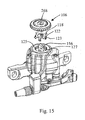
- FIG. 15 is an exploded view of the inner indexing knob assembly
- FIG. 16A is a perspective view of the mechanical disc brake caliper with a portion of the housing cut away to reveal the pad receiving cavity;
- FIG. 16B is a sectional view of the mechanical disc brake caliper taken along line 16 B- 16 B of FIG. 10;
- FIG. 17A-C are alternate embodiments of the backing plates of the brake pad assemblies
- FIG. 18 is identical to FIG. 16, only showing the pad assembly installed with the pad assembly recess;
- FIG. 19 is a perspective view of the outer knob
- FIG. 20 is a perspective view of the outer knob from a perspective rotated 180° from that of FIG. 19;
- FIG. 21 is a perspective view of the inner knob
- FIG. 22 is a perspective view of the inner knob taken from a perspective rotated 180° from that of FIG. 21;
- FIG. 23 is a front view of the lever arm illustrating the progressive, eccentric shape of the cable guide surface
- FIG. 24 is a front view of the lever arm illustrating the constant, concentric shape of the cable guide surface
- FIG. 25 is a perspective view of a ball retainer
- FIG. 26 is a sectional view of a ball retainer taken along line 26 - 26 of FIG. 25 with a ball engaged therein;
- FIG. 27 is a perspective view of an alternate embodiment of a ball retainer
- FIG. 28 is a sectional view taken along line 28 - 28 of FIG. 27 with a ball engaged by the retainer;
- FIG. 29 is a plan view of an alternate embodiment of ramped grooves in a fixed cam.
- FIG. 1 A mechanical disc brake caliper 10 in accordance with the present invention is shown in FIG. 1 mounted to a frame or, more particularly, a front fork 12 of a bicycle in operative engagement with a disc 14 .
- the caliper 10 is mounted to a front fork 12 for use with a front wheel.
- the caliper is typically mounted to the seat stay, chain stay, drop out plate, after market adapter or the like.
- the disc 14 in turn is rigidly mounted to the hub of a wheel assembly by the bolts 16 .
- the bicycle wheel and hub are not shown.
- the mechanical disc brake caliper consists of a caliper housing 18 having a pair of mounting feet 20 , 22 extending therefrom for attachment to a corresponding pair of internally threaded attachment bosses 24 , 26 which extend from the front fork 12 .
- a pair of mounting bolts 28 secure the mounting feet 20 , 22 to the attachment bosses 24 , 26 .
- the mounting feet preferably include elongate slots 27 (see FIG. 5) receiving the mounting bolts 28 and complimentary pairs of concave/convex washers 30 to provide for adjustable attachment of the mechanical disc brake caliper to a bicycle frame.
- Such an attachment structure is described in detail in applicant Wayne Lumpkin's, co-pending Patent application Ser. No. 09/383,121, the disclosure of which is hereby incorporated in its entirety herein.
- a lever arm 32 is pivotally attached at a first end 34 to the caliper housing 18 .
- a second end of the lever arm 36 has a cable clamp 38 which secures an end of the cable 40 .
- the cable 40 is directed through a cable feed 42 attached to the caliper housing 18 with a cable housing 44 abutting the cable feed 42 .
- the mechanical disc brake caliper is actuated by tension being applied to an opposite end of the cable 40 by a cable actuator such as a conventional cable brake lever (not shown) and this tension causes the lever arm 32 to pivot about pivot axis 46 in the direction of arrow 48 so that the second end of the lever arm 36 is drawn toward the cable guide 42 to advance a brake pad into contact with the disc 14 by a rotary to linear linkage between the first end 34 of the lever arm 32 and the brake pad.
- a cable actuator such as a conventional cable brake lever (not shown) and this tension causes the lever arm 32 to pivot about pivot axis 46 in the direction of arrow 48 so that the second end of the lever arm 36 is drawn toward the cable guide 42 to advance a brake pad into contact with the disc 14 by a rotary to linear linkage between the first end 34 of the lever arm 32 and the brake pad.
- FIG. 2 shows the mechanical disc brake caliper 10 mounted to a front fork 12 ′ having internally threaded attachment bosses 24 ′ and 26 ′ with an axis parallel to the axis of rotation of the disc 14 .
- the mechanical disc brake caliper 10 ′ is in all manner identical to the mechanical disc brake 10 described above with regard to FIG. 1. For simplicity, all unnecessary corresponding reference numbers have been omitted.
- An adapter bracket 60 is fastened by a pair of bolts 62 to the attachment bosses 24 ′, 26 ′ and includes a pair of internally threaded receptor bores 64 that enable the caliper housing 18 to be attached to the front fork 12 ′ in an identical position relative to the disc 14 described above with respect to FIG. 1.
- the adapter bracket provides an equivalent mounting surface to that provided by the attachment bases 24 , 26 , as shown in FIG. 1.
- FIG. 3A is a front elevation view of the mechanical disc brake caliper 10 mounted to a bicycle frame 12 as illustrated in FIG. 1.
- FIG. 3 differs from FIG. 1 by the inclusion of the floating cable stop 70 , which will be described in greater detail below.
- FIG. 4A The mechanical disc brake caliper 10 is shown in an exploded perspective view in FIG. 4A.
- FIG. 4B is identical to FIG. 4A, only the perspective is rotated 180°.
- First and second brake pad assemblies 72 , 74 consist of mirror image backing plates 76 , 78 each having a trailing surface 80 including a post receiving receptacle 81 and a leading surface 82 to which a brake pad 84 is permanently adhered.
- the mechanical disc brake caliper When the mechanical disc brake caliper is operatively associated with a disc 14 , the disc 14 resides between the pads 84 of the first and second brake pad assembly 72 , 74 which are held in place in part by a pad retention clip 85 in a manner which will be described in greater detail below.
- the second brake pad assembly 74 is also known as the back or inboard brake pad assembly.
- a pad wear compensator 73 for the inboard pad assembly includes inboard pressure foot 86 , which as discussed below, functions as an indicator.
- the inboard brake pad assembly 74 is attached to the inboard pressure foot 86 by means of a washer-shaped magnet 88 which is adhered to a cooperatively shaped receptacle 90 in the leading surface 92 of the inboard pressure foot 86 .
- An axial post 94 extends through the hole in the washer-shaped magnet 88 and protrudes beyond the leading surface 92 to engage the post receiving receptacle 81 in the trailing surface of the backing plate.
- a trailing portion or indicator dog 96 having a rectangular cross-section extends from a trailing surface of the inboard pressure foot 86 along the same axis of the axial post 94 .
- the edge of the inboard pressure foot 86 is threaded as indicated at 100 between the leading surface 92 and the trailing surface 98 .
- the threads 100 are sized to threadably engage complimentary threads 102 in the inner diameter of an inside cylinder 104 of the caliper housing 18 (see FIGS. 4B and 5). This threaded engagement allows for linear advancement of the pressure foot as it is rotated.
- An inboard pad advancement adjustment knob 106 has knurled edge 108 , an axial orifice or hole 110 .
- the axile hole is configured snugly, axially, slidably receive the indicator dog 96 of the inboard pressure foot 86 but to prevent rotation between the pressure foot and the adjustment knob.
- An inside indexing spring clip 116 has a plurality of radially extending legs 118 sized to be received between the axially inwardly extending legs 112 of the inner knob 106 .
- the inside indexing spring clip 116 further includes axially inwardly extending bars 122 having radially outward extending detents 123 at their distal ends. As best seen in FIG.
- the dog 96 extends through the hole 126 in the inside indexing spring clip 116 and into the axial hole 110 in the inner knob 106 .
- the barbs 114 engage an inner edge of an inward extending annular flange 125 to lock the inner knob 106 against axial movement.
- the detents 123 in turn engage equally radially spaced indexing knurls 127 in the inner surface of the flange 125 .
- the complimentary detents and indexing knurls provide a tactile indication of pad adjustment as the inboard knob 106 is rotated.
- the caliper housing 18 also includes an outboard cylinder 128 which is coaxial with the inboard cylinder 104 .
- the bulk of the remaining components of the mechanical disc brake caliper 10 reside within the outboard cylinder 128 .
- the outboard cylinder 128 has an annular groove 130 (see FIG. 4B) in its inner diameter sized to receive the hoop-shaped polymer dust seal 132 .
- Outboard pressure foot 134 has an identical leading surface to the leading surface 92 of the inboard pressure foot 86 and identical reference numbers are used in FIG. 4B.
- Washer-shaped magnet 88 ′ which is identical to washer-shaped magnet 88 , is adhered within the cooperative shaped receptacle 90 of the leading surface 92 of the outer pressure foot 134 .
- the outside or first brake pad assembly 72 is attached by the washer-shaped magnet 88 ′ to the leading surface of the outer pressure foot 134 .
- the trailing surface 136 has an axially extending post 138 having an annular groove 140 in its sidewall near the distal end. In the distal end is an axial cup 142 .
- Split ring 144 is sized to be received in the annular groove 140 .
- Ball bearing 146 is sized to be received in and to extend axially from the axial cup 142 .
- An indicator foot screw 148 has a head 149 with a leading surface 150 which abuts the ball bearing 146 . Behind the head 149 is a shaft 152 which is threaded adjacent to the head 149 as indicated at 154 . The trailing end of the shaft 152 has a pair of flats 156 (one shown in FIG. 4A) on opposite sides.
- the indicator foot screw 148 is an integral part of a pad wear compensator 153 for the outboard brake pad assembly.
- Drive cam 158 has an enlarged diameter base 160 having a plurality of equally spaced curved, ramped grooves 162 in its trailing surface. The preferred embodiment has three ramped grooves 162 spaced at 120°.
- a cylindrical shaft 164 extends rearward of the enlarged diameter base 160 and has an axial bore 166 which extends axially through the drive cam 158 .
- the axial bore includes a threaded inner diameter portion 168 which threadably engages the threaded portion 154 of the foot screw 148 with the shaft 152 extending rearwardly from the axial bore 166 .
- an inwardly extending flange 170 acts as a stop against a rearward portion of the head 149 .
- the distal end of the outside cylindrical shaft 164 is threaded at 172 and adjacent the treaded portion 172 is a hex portion 174 .
- One of three ball bearings 176 resides in each ramped groove 162 .
- the outer diameter of the enlarged diameter base 160 is sized to fit snuggly within the inner diameter of the outside cylinder 128 and have a sealing relationship with the dust seal 132 as best seen in FIGS. 5 and 7.
- Fixed cam 178 has a generally cylindrical body 180 with a constant inner diameter orifice 182 .
- An intermediate step 184 has a spring tension limiting boss 186 which extends axially onto-the cylindrical body 180 .
- a leading step 188 has an outer diameter greater than that of the intermediate step 184 and an enlarged outside diameter annular flange 190 rises from the leading step 188 adjacent the intermediate step 184 .
- a locking boss 192 extends toward the leading surface 193 collinearly with the spring tension limiting boss 186 at a height matching that of the enlarged outer diameter annular flange 190 .
- the locking boss 192 is sized to key into a receiving slot 194 in the inner diameter of the outside cylinder 128 to lock the fixed cam 178 against axial rotation (see FIG. 4A).
- the leading surface of the enlarged outer diameter annular flange 190 abuts a step 196 in the inner diameter of the outside cylinder 128 to halt axial insertion of the fixed cam 178 into the outside cylinder 128 from the opened end as viewed in FIG. 4A.
- the engaged relationship can best be seen in FIG. 5.
- the leading surface 193 of the fixed cam 178 is best viewed in FIG. 4B.
- the leading surface has a plurality of equally radially spaced ramped grooves corresponding to the ramped grooves of the drive cam 158 .
- FIG. 4B shows three ramped grooves 200 spaced at 120° which correspond to the ramped grooves 162 of the drive cam 158 , only with the ramps extending radially in opposite directions when aligned as shown in FIGS. 4A, 4B and 5 - 7 .
- a ball bearing 176 resides between each ramped groove pair 162 , 200 as best viewed in FIGS. 5 - 7 . Referring to FIG. 5 , with balls residing in the grooves 162 , 200 , the grooves and ball bearings act as an angular contact bearing which is able to accommodate axial loads on the drive cam exerted by the lever arm 32 .
- the ramped grooves self-center the drive cam shaft 164 within the inner diameter 182 of the fixed cam 178 with the drive cam under an axial load.
- This feature eliminates the need for an optional split bushing (not shown) being press fit in the inner diameter 182 of the fixed cam 178 . It further eliminates friction between the drive cam shaft 164 and fixed cam 178 . It further reduces needs for tight tolerances between the drive cam shaft 164 and fixed cam 178 , thus eliminating the need for costly centerless grinding of the drive cam shaft and reaming of the fixed cam bore 182 .
- the fixed cam When the fixed cam is seated within the outside cylinder 128 as described above and as viewed in FIG. 5, it is locked against axial movement by locking ring 204 which has a threaded outer diameter 206 and evenly spaced engagement slots 208 in the inner diameter 210 .
- the inner diameter is sized to snugly receive the intermediate step 184 of the fixed cam 178 and the engagement slots 208 allow for engagement by a special turning tool (not shown) so that the threaded outer diameter 206 can be brought into threaded engagement with corresponding threads 212 in the inner diameter of the outside cylinder 128 .
- a generally washer-shaped spring tension biasing plate 220 has an inner diameter which snugly axially receives the intermediate step 184 of the fixed cam 178 and includes a spring tension limiting slot 222 which receives the spring tension limiting boss 186 .
- a cut in the outer diameter of the spring tension biasing plate forms a stop surface 224 .
- Near the stop surface 224 is a hole 226 .
- Return spring 228 has a pair of axially extending ends 230 , 232 .
- the inner diameter of the return spring 228 is large enough to axially receive the fixed cam 178 and the shaft 164 of the drive cam 158 as best viewed in FIG. 5.
- the axially extending end 230 is received in the hole 226 of the spring tension biasing plate 220 (see FIG.
- a dust seal 234 defines an annular cover 236 for the return spring 228 as seen in FIG. 4B and FIGS. 5 - 7 .
- the inner diameter of the trailing orifice 238 is sized to receive and have a sealing relationship with the outer diameter of a leading flange 240 of the lever arm 32 .
- a hole 242 in the trailing surface of the cover 236 receives the axially extending rod 232 .
- the axially extending rod 232 in turn is received in the hole 244 near the first end 34 of the lever arm 32 .
- a hex orifice 246 near the first end 34 of the lever 32 axially receives the hex portion 174 of the cylindrical shaft 164 of the drive cam 158 with a hex inner diameter washer 248 therebetween to radially fix the lever arm 32 to the drive cam 158 .
- Washer 252 abuts the trailing surface 254 and is sandwiched by a larger outer diameter washer 256 .
- the larger outer diameter washer 256 has a number of equally radially spaced indexing knurls 258 in its outer diameter.
- the washers 252 , 256 and the lever arm 32 are axially secured to the cylindrical shaft 164 of the drive cam 158 by nut 260 which threadably engages the threaded portion 172 of the cylindrical shaft 164 .
- An outboard knob 264 has a knurled edge 266 and an orifice or axial hole 268 sized and dimensioned to snugly receive the flats 156 of the trailing end of the foot screw 148 therein, as illustrated in FIG. 5.
- a plurality of axially inwardly extending legs 270 are equally radially spaced in an inside surface of the outer knob 264 .
- At the distal end of each axially inwardly extending leg 270 is an inwardly protruding barb 272 .
- An outside indexing spring clip 274 has a plurality of axially extending bars 276 each having an inwardly extending detent 278 near its distal end.
- the axially extending bars 276 are sized to snugly fit between the axially inwardly extending legs 270 of the outboard knob (see FIG. 4A).
- the outer knob 264 With the outside indexing spring clip axially engaged with the outer knob 264 in the orientation illustrated in FIG. 4A, the outer knob 264 is axially advanced over the nut 260 and the inwardly protruding barbs 272 lockingly engage the outer diameter edge of the large outer diameter washer 256 to lock the outer knob 264 against axial movement.
- the inwardly extending detents 278 of the outside indexing spring clip engage the indexing knurls 258 of the larger outer diameter washer 256 . This can be best seen in detail with reference to FIGS. 14 and 5.
- the complimentary detents and indexing knurls provide a tactile indication of pad advancement as the outboard knob 264 is rotated.
- the cable feed 42 consists of a mount 284 which is preferably integrally cast with the housing 18 .
- the mount 284 includes an orifice 286 centered along a guide axis 288 .
- a cylindrical housing stop ferrule 290 has a cylindrical main body 292 having an outer diameter dimensioned to fit freely yet snugly within the orifice 286 .
- a minor boot retention barb 294 extends axially from a leading end of the housing stop ferrule.
- a major boot retention barb 296 extends axially from a trailing end of the housing stop ferrule 290 .
- An annular retention flange 298 extends radially from the main body 292 adjacent to the major boot retention barb 296 and forms a stop which halts axial insertion of the housing stop ferrule 290 into the orifice 286 , as best seen in FIG. 12. Further referring to FIG. 12, the inside of the housing stop ferrule 290 has a trailing portion having an inner diameter slightly larger than that of a standard cable housing to axially receive the cable housing 44 therein. An annular flange 302 extends inwardly to define a cable guide orifice 304 . The inner diameter of the minor boot retention barb 306 is of a size between that of the trailing inner diameter 300 and the cable guide orifice 304 .
- a hollow minor retention boot 310 is molded of an elastomeric material and at its trailing edge has an inwardly extending annular flange 312 configured to lockingly engage with the minor boot retention barb 294 of the housing stop ferrule 290 .
- the minor retention boot has a leading nipple 314 having a leading hole 316 with an inner diameter slightly less than the outer diameter of the standard bicycle brake cable 40 . In this manner, the leading nipple forms a wipe seal with the brake cable 40 as seen in FIG. 12.
- a hollow major retention boot 320 molded of an elastomeric material has an inwardly extending annular flange 322 sized to lockingly engage with the major boot retention barb 296 on the trailing end of the housing stop ferrule 290 as best viewed FIG. 12.
- the trailing end 324 has a tapered inner diameter, which at the extreme trailing end is slightly smaller than the outer diameter of the standard cable housing to form a sealing relationship therewith.
- a curved horn 330 defining an axially flat, radially curved cable guide surface 332 extends from a trailing end of the second end 36 of the lever 32 .
- the curved horn 330 curves about the axis of rotation 46 of the lever arm 32 .
- the curved horn is eccentric about the axis as illustrated schematically in FIG. 23 to provide for progressive increase in power as the lever is actuated by a cable 40 .
- the curved horn can be concentric as shown in FIG. 24 or eccentric and regressive, which though not illustrated, would require the curved horn to have an increasing radius as it extends toward its free end, essentially the opposite of the progressive horn illustrated in FIG. 23.
- the cable clamp 38 consists of a screw 334 having a threaded shaft 336 sized to threadably engage an internally threaded bore in the lever arm 32 having an axis normal to the axis of rotation 46 .
- a clamp plate 338 is secured between the head of the screw 334 and the second end 36 of the lever arm 32 .
- the clamp plate has a tab 340 which is received in a notch 342 defined in the distal end of the lever arm 32 to fix the clamp plate against rotation.
- a groove 344 is formed in the underside of the clamp plate adjacent to the notch 342 to receive the cable 40 and has a number of protrusions 345 extending therein to improve the grip of the cable, as illustrated in FIG. 4B.
- the curved horn 330 is configured so that with the mechanical disc brake caliper installed on a bike frame as illustrated in FIGS. 1 - 3 B, the guide axis 288 is essentially tangent to the free end of the curved horn 330 .
- Essentially tangent means a cable 40 does not have a significant bend when it contacts the cable guide surface 332 , but instead has a very gradual transition to the cable guide surface 332 as viewed in FIG. 3.
- a tension actuator such as a conventional bicycle brake lever
- the lever arm 32 is drawn toward the cable feed 42 . Because of the radially curved cable guide surface 332 , the fixed cable clamp and the fixed cable feed 42 , no sharp bends are introduced to the cable 40 which might fatigue the cable and lead to premature failure of the cable, which could have disastrous results for a user.
- the conventional cable housing extends from the trailing end of the major retention boot 320 .
- An improvement to this conventional brake setup is to provide a floating cable stop 70 mating with the trailing inner diameter 300 of the housing stop ferrule 290 as illustrated in FIG. 3A.
- the floating cable stop 70 consists of a axially and radially rigid tube 348 made of a suitable material such as a metal like aluminum or stainless steel or an exceptionally rigid thermoplastic.
- axially and radially rigid means the tube 348 has sufficient rigidity that it will not buckle about its lengthwise axis upon application of tension within the normal range of operating tensions applied to the cable 40 which runs within the tube 348 .
- the tube 348 has a standard cylindrical cross-section (see FIG. 3C), although other cross-sections may be useful or desired.
- the outer diameter is preferably essentially the same to that of a standard cable housing 44 so that it can fit into a trailing end of the housing stop ferrule 290 in the same manner as the housing 44 as illustrated in FIG. 12.
- a connector ferrule 350 connects the tube 348 to a conventional cable housing 44 .
- the conventional cable housing allows the cable to be axially deflected as may be required to attach the cable to a brake lever.
- a significant advantage of the floating cable stop 70 is that when it replaces conventional cable housings, it provides a straight path for the cable inside with minimal or no contact with the inner diameter of the tube.
- the axially flexible cable housing will buckle about the lengthwise axis under application of even minor tension to the cable within and the resultant compression to the cable housing. Elimination of this buckling further reduces contact of the cable with the inner diameter of the tube and serves to further minimize friction on the cable.
- the floating cable stop can be deployed wherever there is a straight length of cable, independent of fixed housing stops on the bicycle frame. It also provides a protective barrier for the cable, much like conventional cable housing, but at a lesser weight.
- a small length of conventional housing 352 is disposed between the tube 348 and the housing stop ferrule 290 and is joined to the tube 348 by connector ferrule 354 .
- the transition housing 352 is advantageous because it will flex in the event of a lateral blow to the tube 348 and thereby minimize the risk of bending of the tube 348 which would detract somewhat from its performance and could even result in undesired buckling of the tube 348 .
- the transition housing 352 is of a length that will not buckle under application of operating tensions to the cable 40 but will still provide sufficient axial flexibility to protect the tube 348 .
- the transition housing 352 could be long enough to bend the cable as required to properly cable to the cable feed.
- an apparatus such as the ROLLAMAJIG, manufactured to Avid, L.L.C., of Englewood, Colo., U.S. Pat. No. 5,624,334, the disclosure of which is hereby incorporated by reference, could be substituted for the transition housing to minimize friction where a bend is required to direct the cable.
- floating cable stop 70 could be deployed on any cable actuated bicycle component, including cantilevered brakes, caliper brakes, side pull caliper brakes and derailleurs.
- the first and second brake pad assemblies 72 , 74 are made to be removable from the caliper housing when a rotor is not operatively associated with the caliper housing between the brake pad assemblies.
- a retention structure for the first and second brake pad assembly 72 , 74 is illustrated.
- the caliper housing has a cavity 360 configured to receive the disc or rotor 14 .
- the cavity 360 has a mouth 362 at a leading end and includes a pair of opposing recesses 364 (one shown in FIG. 16A).
- the recesses 364 are configured to nest the backing plates 76 , 78 of the brake pad assemblies 72 , 74 on opposite sides of the disc so that the friction pads 84 can be brought into and out of engagement with the disc by an actuating or drive apparatus along an advancement axis 366 in a manner that will be described in greater detail below.
- a retention tab 370 formed from a pair of extending posts 372 , 374 having oppositely extending protrusions 376 .
- a retention clip cavity 378 opening into the cavity 360 .
- Engagement flanges 380 extend from opposite sidewalls of the retention clip cavity.
- Pad retention clip 85 is shown in FIG.
- the pad retention clip 85 has a base 382 with a pair of extending sidewalls or legs 384 , 386 with a retention detent 388 near the far end of each leg protruding inwardly.
- a plurality of retention barbs 390 extend laterally from the sidewalls or legs 384 , 386 . As illustrated in FIG. 16B, these retention barbs 390 are configured to snap fit with the engagement flanges 380 to lock the pad retention clip 85 within the retention clip cavity 378 .
- the pad assembly 72 is installed by grasping the handle 392 and advancing the leading edge 368 into the mouth 362 along the engagement axis 394 and aligning the retention tab 370 with the pad retention clip 85 and further advancing the pad assembly so that the protrusions 370 mate within the retention detents 388 .
- the pad can then be slid into the recess 364 along the advancement axis 366 to seat the pad assembly within the recess 364 , as viewed in FIG. 18.
- the walls of the recess 364 secure the pad assembly against movement transverse the advancement axis 366 as a rotating disc is engaged. As best viewed in FIG.
- the axial post 94 of the respective inboard or outside pressure foot 86 , 134 is received within the receptacle 81 and the trailing surface 80 of the backing plates to thereby prevent withdrawal of the pad assembly from the mouth 362 of the cavity 360 with the brake pad seated as illustrated in FIG. 18.
- This connection is also the primary support against withdrawal along the engagement axis as the pad assembly is advanced and withdrawn by the actuation mechanism.
- the magnet 88 or 88 ′ holds the backing plate in abutment with the respective pressure foot 86 , 134 to maintain engagement between the axial post 94 and the receptacle 81 .
- the cooperating engagement flanges 380 of the pad retention clip and the protrusions 376 of the pad retention tab define a rail facilitating movement forward and backward along the advancement axis.
- the pad clips can be easily removed from the orifice simply by manually advancing them inward along the advancement axis to bring the receptacle 81 out of engagement with the axial post 94 whereupon the engagement flanges 380 can be snapped out of engagement with the protrusions 376 .
- the handle 392 has straight edges. To facilitate gripping, the handle may be modified as shown in FIGS. 17 A-C. In FIG.
- the handle has a distal enlargement 395 .
- the handle has grooves 396 .
- the handle has knurls or bumps 397 .
- Other grip enhancing structures will also be apparent to those skilled in the art.
- FIG. 10 illustrates that with the lever arm 32 in an at rest position, the cable extends between the cable clamp 38 and the cable feed 42 at a slight angle.
- the lever arm 32 rotated about the pivot axis in the direction of arrow 48 so as to bring the pads into engagement with the disc, the lever arm advances axially along the advancement axis with the outer brake pad assembly 72 so that this slight angle is eliminated, as seen in FIG. 11.
- the axially flat, radially curved cable guide surface 332 be wide enough in the axial direction to accommodate the axial movement of the lever arm 32 .
- the present invention provides a pad wear compensating apparatus that allows for such advancement (or retraction) by rotary to linear linkages between the knobs 106 , 264 and the respective pressure feet 86 , 134 and associated pads.
- the pad wear compensator includes inboard pressure foot or inboard indicator 86 which is threadably engaged with the sidewall of the inside cylinder. Rotation of the inner knob 106 in a clockwise direction advances the pressure foot within the cylinder and therefore the pad assembly along the advancement axis as illustrated in FIG. 6. As the pressure foot is advanced, the trailing end or indicator dog 96 received in the axial hole 110 of the inside knob 106 advances, to provide both a visual and tactile indication of the amount the pressure foot has advanced within the inside cylinder.
- each tactile click equates to ⁇ fraction (1/16) ⁇ of a full rotation and ⁇ fraction (1/16) ⁇ of a millimeter of pad advancement.
- the inboard pad assembly is retracted by rotating the inside knob counter-clockwise.
- the outboard pad wear compensation apparatus 153 relies on a similar rotary to linear linkage as the inboard pad compensator 73 , but it is slightly more complicated. Rotation of the outside knob 264 in a clockwise direction in turn causes rotation of the indicator foot screw 148 in a clockwise direction. This rotation threadably advances the indicator foot screw 148 relative to the drive cam 158 which in turn advances the ball bearing 146 , the outside pressure foot 134 and the corresponding first brake pad assembly 72 . The outside pressure foot in its advanced position is illustrated in FIG. 6. It should be noted that the split washer 141 received in the annular groove 140 causes friction between the outside pressure foot and the fixed cam to prevent the outside pressure foot from simply sliding out of the outside cylinder.
- the outside knob also provides a tactile indication of rotation corresponding to a select linear advancement. This is provided by the inwardly extending detents 278 , which engage with the indexing knurls 258 of the larger outer diameter washer 256 .
- advancement of the indicator foot screw 148 and therefore the outside pressure foot 134 can be monitored visually and by feel by noting how far the trailing end 156 of the indicator foot screw 148 advances relative to the outer surface of the outer knob 264 within the axial hole 268 .
- the outside knob is rotated counter-clockwise to retract the indicator foot screw 148 and the drive mechanism is actuated to squeeze the disc, which in turn retracts the outside pad assembly 72 and the outside pressure foot 134 by forcing them into abutment with the retracted foot screw 148 .
- the pad wear compensating apparatus not only allows for convenient advancement of the brake pad assemblies as the brake pads wear, but the structure also provides a quick and convenient way to properly align the caliper housing 18 relative to a disc 14 . This can be done by loosening the mounting bolts 28 and then advancing the pad assemblies into contact with the disc using the inboard and outboard pad wear compensators 73 , 153 . With the disc squeezed between the pads, the mounting structure including the slotted mounting feet 20 , 22 and the concave and convex washers 30 enables precise alignment of the caliper housing to maintain the leading pad surfaces parallel to the disc. Tightening the mounting bolts 28 , 30 then secures the precise alignment.
- the inner pad assembly is stationary, it is generally preferred to provide a very small clearance between the inner pad and the disc and a greater clearance between the moveable outer pad and the disc.
- This set up can be achieved by starting with the pads fully withdrawn along the advancement axis into the cavity 360 as shown in FIG. 5 and then advancing the inner pad assembly using the inner knob a short distance while advancing the pad associated with the outer knob a greater distance into contact with the disc. The mounting bolts are then tightened and the knobs are turned to retract the pad assemblies to provide a desired operative gap with the disc.
- the pad advancement structure in combination with the caliper housing mounting system also provide for simplified field repair. For example, if a user crashes and one of the attachment bosses is bent, the user can detach the mounting bolts 28 , bend the bent attachment boss back in position as well as possible by eye-balling it and then reposition the caliper housing with the brake pads properly aligned parallel to the disc simply by repeating the procedure described in the preceding paragraph.
- the mechanical disc brake housing has a pair of threaded bores 400 , 402 , which extend the width of the-housing on opposite sides of the pivot axis 46 .
- a steel screw 404 threadably engages each threaded bore 400 , 402 and is tightened to pre-stress or pretension the caliper housing.
- the screws are preferably tightened to apply a compression force of about 1,000-1,400 lbs. This not only prevents cracking and failure of the housing, it virtually eliminates any flexure of the housing that could dissipate braking power or fatigue the housing.
- the mechanical disc brake caliper 10 also includes a mechanism for adjusting the return force on the lever arm 32 applied by the return spring 228 .
- adjustment screw 410 is threadably received in a threaded bore 412 in the housing which breaches the outer cylinder with the axis of the bore 412 aligned with the stop surface 224 of the spring tension biasing plate 220 .
- the spring tension biasing plate 220 rotates about the cylindrical body 180 of the fixed cam 178 to increase the tension on the spring.
- Turning the adjustment screw 410 to retract it from the bore causes rotation of the spring tension biasing plate 220 which decreases the tension on the spring 228 .
- the spring tension limiting slot 222 cooperates with the spring tension limiting boss 186 of the fixed cam 178 to limit rotation of the spring tension biasing plate 220 and therefore the range of return force applied to the lever arm 32 .
- FIGS. 25 and 26 it may be useful or desirable to provide a ball spacer between the drive cam 158 and the fixed cam 178 to maintain the ball bearings 176 equally spaced within the elongated ramped grooves 162 , 200 .
- a ball spacer is to be used, one embodiment of a design for such a ball spacer is illustrated in FIGS. 25 and 26.
- the ball spacer 420 could be made of a simple sheet metal stamping consisting of a ring body 422 with inwardly extending radial leg pairs 424 spaced to correspond to the desired spacing of the ball bearings.
- the radial legs 424 can be curled as illustrated in FIG. 25 to define a ball receiving socket 426 .
- FIGS. 27 and 28 depict another embodiment of a ball spacer molded of plastic. Notches 427 in a ring 428 are sized to snap fit with the ball bearings 176 .
- the ring is thick enough and the insides of the notch are slightly concave (see 429 in FIG. 27) to secure the ball bearing about an axis as illustrated in FIG. 28.
- Either ball spacer embodiment secures the ball bearings 176 about an axis and thus ensures that the ball bearings 176 will maintain an equal radial spacing and further ensures that the ball bearings will be the same distance between the face of the drive cam and the fixed cam.
- the ramped groove structure of the fixed cam and drive cam illustrated in FIGS. 4A and 4B is useful for most applications, but it limits the amount the lever arm can be rotated to, at most, slightly under 120°.
- An alternate ramp structure is depicted in FIG. 29. As illustrated in FIG. 29, the ramps 430 spiral inward as they ramp upward toward the leading surface 432 . With such corresponding structures provided in the leading surface of the fixed cam and the drive cam, the ramped grooves 430 can be much greater in length and have a much more gradual incline. This will enable the associated lever arm 32 to rotate much greater than 120° and for the inboard brake pad to be advanced linearly at a slower rate as the lever arm 32 is pivoted.
- the outer knob is shown in a perspective view in FIG. 19.
- the outer knob has an elongate slot 440 corresponding to each axially inwardly extending leg 270 .
- each elongate slot 440 overlies a corresponding barb 272 .
- the holes 440 are formed during molding of the outer knob 264 by a mandrel which occupies the space that defines the hole 440 , with the distal end of the mandrel contributing to the forming of the undercut of the barb. In this manner, the undercuts are introduced to the knob while still enabling the knob to be injection molded in a single step. Referring to FIGS.
- the inner knob 106 likewise has elongate slots 442 corresponding to each inward axially extending leg 112 .
- the slots overly the barbs 114 and enable formation of the undercut on the barbs by means of mandrels as described above with regard to the inner knob.
Landscapes
- Engineering & Computer Science (AREA)
- General Engineering & Computer Science (AREA)
- Mechanical Engineering (AREA)
- Transportation (AREA)
- Health & Medical Sciences (AREA)
- Oral & Maxillofacial Surgery (AREA)
- Braking Arrangements (AREA)
Abstract
A bicycle disc brake caliper includes a housing configured to be rigidly fixed to a bicycle frame containing a pair of opposing brake pad assemblies configured to reside on opposite sides of a disc operatively associated therewith. At least one of the brake pad assemblies is advanced and retracted relative to the disc by a drive mechanism along an advancement axis to effect braking. A pad wear compensation apparatus is operatively associated with at least one of the brake pad assemblies to advance the brake pad assembly along the advancement axis as it wears. The pad wear compensation apparatus includes an adjustment knob attached to the housing for rotation about a rotation axis and fixed against axial movement. A rotary to linear linkage between the linked brake pad assembly and the knob provides axial advancement of the brake pad assembly relative to the housing upon axial rotation of the knob in a select direction to fix a select distance between the at least one linked brake pad assembly and the disc with the brake pad assembly retracted.
Description
- This application is a continuation of U.S. patent application Ser. No. 10/179,772, filed Jun. 25, 2002, entitled “Fixed Disc Brake Caliper with Pad Wear Compensator,” which is a continuation of U.S. patent application Ser. No. 09/685,284, filed Oct. 10, 2000, entitled, “Cable Feed for a Mechanical Ball Bearing Disc Brake,” which claimed priority from U.S. Provisional Patent Application Serial No. 60/195,560, filed Apr. 6, 2000, entitled “Mechanical Disc Brake Caliper.”
- The present invention is directed toward disc brakes, and more particularly toward a pad wear compensator for a disc brake caliper.
- Disc brakes are being included on more and more bicycles as consumers are ever increasingly demonstrating a preference for disc brakes over conventional rim brakes such as caliper brakes, cantilever brakes and side pull cantilever brakes. While both mechanical and hydraulic disc brakes have been available for bicycles for many years, only recently have there been advances in disc brake caliper design that have made disc brakes sufficiently lightweight, reliable and inexpensive to satisfy consumer preferences. While more efficient and powerful caliper drive mechanisms are evolving, to date manufacturers of disc brakes have not adequately addressed consumer need for ease of adjustment and maintenance of these caliper brakes. One area of particular concern is structures for compensating for pad wear.
- One known pad wear compensator provides a set screw that can be advanced within a caliper housing to advance an operatively associated brake pad as the pad wears. The set screw resides within a threaded bore in the housing and requires a turning tool such as a hex wrench to advance the pad. In addition, to lock the pad in a select position, a second locking screw is threadably engaged in the bore to lock the adjustment screw in place. This structure, while allowing for advancement of the pad to compensate for pad wear, is extremely cumbersome to use, requiring the removal of one screw and the turning of two screws as well as the use of a separate tool to make an adjustment. In addition, because the adjustment screw resides within the threaded bore, there is no reliable way to gauge how far the pad has been extended so as to assess remaining pad life. Furthermore, the structure fails to provide any indexing to insure select axial advancement of the brake pad as the adjustment screw is rotated.
- Another known pad wear compensator provides a knob which can be rotated to advance the caliper housing relative to a disc operatively associated with the housing so as to compensate for brake pad wear. While this structure overcomes some of the complexity and tool requirements of the structure discussed in the preceding paragraph, it still has numerous deficiencies. Most notably, by providing for advancement of the entire housing relative to the disc as opposed to simply advancement of the pad itself relative to the housing and the disc as it wears, the advancement structure must reside outside of the housing and is thus subject to damage and abuse in use. In addition, while this structure does allow for observation of how far the housing has been advanced relative to the disc, it does not provide a reliable indication of pad wear, as adjustment of the housing may be dictated by other factors such as disc alignment.
- Yet another known pad wear compensator provides a knob which threadably engages a caliper housing. The knob can be rotated relative to the caliper housing and thus advanced and retracted axially of the housing. As the knob is rotated to advance it relative to the housing it also advances a pad actuation mechanism along with a pad assembly associated therewith to advance the pad assembly. The opposing pad is fixed against movement relative to the housing. However, the housing itself is moveable relative to a disc so that by movement of the caliper housing and movement of the pad wear compensation knob, pad wear on each of the pads can be compensated for. This structure is still very cumbersome in that only one pad can be advanced relative to the housing. In addition, the knob both rotates and is advanced relative to the housing, providing a potential avenue for grit and other contaminates to effect smooth operation of the caliper actuation mechanism. Finally, because the housing itself is moveable relative to the disc to enable compensation of the fixed pad, there is no reliable indication of how much wear the respective pads have experienced.
- German Patent Publication DE 2648765 A1 discloses yet another system to compensate for the wear of brake pads on a disc brake. This system includes a caliper housing which floats on an attachment bracket relative to a frame to which the caliper brake is attached. A pair of brake pad assemblies within the caliper housing receive a disc therebetween. A drive mechanism is operatively associated with a first one of the brake pad assemblies to advance and retract the first brake pad assembly relative to the disc along an advancement axis to effect braking. An adjustment knob is attached to the housing for rotation about a rotation axis. A rotary to linear linkage provides axial advancement of the first brake pad assembly relative to the housing upon axial rotation of the knob in a select direction. While this structure has the advantage of providing axial advancement of a brake pad assembly relative to a caliper housing, because the caliper housing floats it does not provide a structure for fixing a select distance between a brake pad and a brake disc. As a result, the structure taught in DE 2648765 A1 does not eliminate the possibility of the linked brake pad assembly contacting the disc when in the retracted position. This can be a considerable problem for use in bicycles where such contact results in friction diminishing the efficient turning of the bicycle wheels. DE 2648765 A1 further fails to teach or suggest any structure for indication of pad wear. Moreover, because DE 2648765 A1 teaches a floating caliper, there is no teaching or suggestion of any desirability of providing a structure for advancing the brake pad which is not operatively associated with the drive mechanism.
- The present invention is intended to overcome one or more of the problems discussed above.
- A mechanical bicycle disc brake includes a caliper housing configured to be rigidly fixed to a bicycle frame. A pair of brake pad assemblies are received within the housing and are configured to reside on opposite sides of the disc operatively associated therewith. At least one brake pad assembly is operatively associated with a drive mechanism configured to advance and retract the brake pad assembly relative to the disc along an advancement axis to effect braking. An adjustment knob is attached to the housing for rotation about a rotation axis but fixed against axial movement. A rotary to linear linkage is operatively associated with at least one of the brake pad assemblies and the knob to provide axial advancement of the at least one linked brake pad assembly relative to the housing and the disc upon axial rotation of the knob in a select direction to fix a select distance between the at least one linked brake pad assembly and the disc with the at least one brake pad assembly retracted. The mechanical bicycle disc brake my further include an indicator visibly observable outside the housing. The indicator is operatively associated with the rotary to linear linkage to advance with the brake pad assembly as the adjustment knob is rotated in the select direction. The rotation axis and the advancement axis may be the same and the visual indicator preferably extends into a hole in the knob along the rotation axis. A tactile indicator may be associated with the knob for providing a tactile indication of advancement of the brake pad assembly along the advancement axis a select amount as the knob is rotated in the select direction. The tactile indicator preferably includes index knurls within the housing that are fixed against rotation relative to the knob and complimentary detents operatively associated with the knob engaging the knurls as the knob is rotated relative to the detents.
- Another aspect of the present invention is a mechanical bicycle disc brake including the caliper housing configured to be rigidly fixed to a bicycle frame. A pair of first and second brake pad assemblies are received within the housing and configured to reside on opposite sides of a disc operatively associated therewith. A drive mechanism within the housing is operatively associated with the first brake pad assembly and configured to advance and retract the first brake pad assembly relative to the disc along an advancement axis to effect braking. A first adjustment knob is attached to the housing for rotation about a first rotation axis but fixed against axial movement. A second adjustment knob is attached to the housing for rotation about a second rotation axis but fixed against axial movement. A first rotary to linear linkage between the first brake pad assembly and the first knob provide axial advancement of the first brake pad assembly relative to the housing and the disc upon axial rotation of the knob in a select direction to fix a select distance between the first brake pad assembly and the disc with the first brake pad retracted. A second rotary to linear linkage between the second brake pad assembly and the second knob provides axial advancement of the second brake pad assembly relative to the housing and the disc upon axial rotation of the knob in a select direction to fix a select distance between the second brake pad assembly and the disc with the first brake pad retracted. An indicator visibly observable outside the housing may be operatively associated with each of the first and second rotary to linear linkages to advance with the respective first and second brake pad assemblies as the first and second adjustment knobs are rotated in the select direction.
- The mechanical bicycle disc brake of the present invention includes a pad wear compensation apparatus that allows for quick and easy advancement of the brake pads relative to the housing to compensate for brake pad wear. The knobs allow for this adjustment to be made without tools, allowing the adjustment to be made anywhere and at any time with minimal effort by the user. Because the knobs rotate but do not advance axially with the remainder of the pad wear compensation apparatus, the opportunity for grit or the like contaminating the apparatus is minimized. The tactile indicator of the pad wear compensation apparatus gives immediate tactile feedback to a user to indicate a select distance of pad advancement for a select increment of rotation of the knob. The pad wear compensation apparatus also includes a visual indicator giving an immediate visual indication to the user of how far the brake pad has been advanced relative to the housing. In this manner a user can continuously monitor the amount of pad wear left so as to minimize the possibility of excessive pad wear during an extended ride which could cause scoring and ultimately the ruining of an associated disc. The mechanical disc brake further allows a brake pad assembly to be fixed a select distance from the disc in a retracted position to eliminate friction causing rubbing. In one embodiment a pad wear compensation apparatus is operatively associated with each brake pad assembly so each brake pad assembly may be independently spaced a fixed select distance from the disc. All these many advantages are provided by the pad wear compensation apparatus that consists of simple mechanical elements that can be produced and assembled inexpensively and which provide highly reliable and convenient adjustment.
- FIG. 1 is a perspective view showing the mechanical disc brake caliper of the present invention mounted to a fork of a bicycle in operative engagement with a brake disc;
- FIG. 2 is the mechanical disc brake caliper of FIG. 1 including an adaptor for mounting to a frame with different mounts;
- FIG. 3A is a front elevation view of the mechanical disc brake caliper of FIG. 1 including a floating cable stop;
- FIG. 3B is identical to FIG. 3A except it further includes an alternate embodiment of the floating cable stop;
- FIG. 3C is a cross-section of the floating cable stop taken along
line 3C-3C of FIG. 3A; - FIG. 4A is an exploded perspective view of the mechanical disc brake caliper of FIG. 1;
- FIG. 4B is an exploded perspective view from a perspective rotated 180° from that of FIG. 4A;
- FIG. 4C is a bottom perspective view of a clamp plate in accordance with the present invention;
- FIG. 5 is a cross-section of the mechanical disc brake caliper taken along line 5-5 of FIG. 3A with the brake pads retracted;
- FIG. 6 is the same as FIG. 5 only with the brake pads extended using the pad wear compensation apparatus;
- FIG. 7 is the same as FIG. 5 only it illustrates the brake pads advanced by the drive mechanism into contact with a disc;
- FIG. 8 is a cross-section of the mechanical disc brake caliper taken along line 8-8 of FIG. 3A;
- FIG. 9 is a cross-section of the mechanical disc brake caliper taken along line 9-9 of FIG. 8;
- FIG. 10 is a right side view of the mechanical disc brake caliper with the lever arm in an at rest position;
- FIG. 11 is a right side elevation view of the mechanical disc brake caliper with the lever arm actuated to the braking position;
- FIG. 12 is a cross-section of the cable feed taken along line 12-12 of FIG. 10;
- FIG. 13 is a front exploded view of the cable feed;
- FIG. 14 is an exploded view of the outer indexing knob assembly;
- FIG. 15 is an exploded view of the inner indexing knob assembly;
- FIG. 16A is a perspective view of the mechanical disc brake caliper with a portion of the housing cut away to reveal the pad receiving cavity;
- FIG. 16B is a sectional view of the mechanical disc brake caliper taken along
line 16B-16B of FIG. 10; - FIG. 17A-C are alternate embodiments of the backing plates of the brake pad assemblies;
- FIG. 18 is identical to FIG. 16, only showing the pad assembly installed with the pad assembly recess;
- FIG. 19 is a perspective view of the outer knob;
- FIG. 20 is a perspective view of the outer knob from a perspective rotated 180° from that of FIG. 19;
- FIG. 21 is a perspective view of the inner knob;
- FIG. 22 is a perspective view of the inner knob taken from a perspective rotated 180° from that of FIG. 21;
- FIG. 23 is a front view of the lever arm illustrating the progressive, eccentric shape of the cable guide surface;
- FIG. 24 is a front view of the lever arm illustrating the constant, concentric shape of the cable guide surface;
- FIG. 25 is a perspective view of a ball retainer;
- FIG. 26 is a sectional view of a ball retainer taken along line 26-26 of FIG. 25 with a ball engaged therein;
- FIG. 27 is a perspective view of an alternate embodiment of a ball retainer;
- FIG. 28 is a sectional view taken along line 28-28 of FIG. 27 with a ball engaged by the retainer; and
- FIG. 29 is a plan view of an alternate embodiment of ramped grooves in a fixed cam.
- A mechanical
disc brake caliper 10 in accordance with the present invention is shown in FIG. 1 mounted to a frame or, more particularly, afront fork 12 of a bicycle in operative engagement with adisc 14. As shown in FIGS. 1-3, thecaliper 10 is mounted to afront fork 12 for use with a front wheel. For use with the rear wheel, the caliper is typically mounted to the seat stay, chain stay, drop out plate, after market adapter or the like. Thedisc 14 in turn is rigidly mounted to the hub of a wheel assembly by thebolts 16. For the sake of clarity, the bicycle wheel and hub are not shown. - The mechanical disc brake caliper consists of a
caliper housing 18 having a pair of mountingfeet attachment bosses front fork 12. A pair of mountingbolts 28 secure the mountingfeet attachment bosses bolts 28 and complimentary pairs of concave/convex washers 30 to provide for adjustable attachment of the mechanical disc brake caliper to a bicycle frame. Such an attachment structure is described in detail in applicant Wayne Lumpkin's, co-pending Patent application Ser. No. 09/383,121, the disclosure of which is hereby incorporated in its entirety herein. - As seen in FIG. 1, a
lever arm 32 is pivotally attached at afirst end 34 to thecaliper housing 18. A second end of thelever arm 36 has acable clamp 38 which secures an end of thecable 40. Thecable 40 is directed through acable feed 42 attached to thecaliper housing 18 with acable housing 44 abutting thecable feed 42. While the operation of the mechanical disc brake will be described in considerably greater detail below, it is useful at the outset to understand that the mechanical disc brake caliper is actuated by tension being applied to an opposite end of thecable 40 by a cable actuator such as a conventional cable brake lever (not shown) and this tension causes thelever arm 32 to pivot aboutpivot axis 46 in the direction ofarrow 48 so that the second end of thelever arm 36 is drawn toward thecable guide 42 to advance a brake pad into contact with thedisc 14 by a rotary to linear linkage between thefirst end 34 of thelever arm 32 and the brake pad. - FIG. 2 shows the mechanical
disc brake caliper 10 mounted to afront fork 12′ having internally threadedattachment bosses 24′ and 26′ with an axis parallel to the axis of rotation of thedisc 14. The mechanicaldisc brake caliper 10′ is in all manner identical to themechanical disc brake 10 described above with regard to FIG. 1. For simplicity, all unnecessary corresponding reference numbers have been omitted. Anadapter bracket 60 is fastened by a pair ofbolts 62 to theattachment bosses 24′, 26′ and includes a pair of internally threaded receptor bores 64 that enable thecaliper housing 18 to be attached to thefront fork 12′ in an identical position relative to thedisc 14 described above with respect to FIG. 1. Thus, the adapter bracket provides an equivalent mounting surface to that provided by the attachment bases 24, 26, as shown in FIG. 1. - FIG. 3A is a front elevation view of the mechanical
disc brake caliper 10 mounted to abicycle frame 12 as illustrated in FIG. 1. FIG. 3 differs from FIG. 1 by the inclusion of the floatingcable stop 70, which will be described in greater detail below. - The mechanical
disc brake caliper 10 is shown in an exploded perspective view in FIG. 4A. FIG. 4B is identical to FIG. 4A, only the perspective is rotated 180°. First and secondbrake pad assemblies image backing plates surface 80 including apost receiving receptacle 81 and a leadingsurface 82 to which a brake pad 84 is permanently adhered. When the mechanical disc brake caliper is operatively associated with adisc 14, thedisc 14 resides between the pads 84 of the first and secondbrake pad assembly pad retention clip 85 in a manner which will be described in greater detail below. - As oriented in FIG. 4A, the second
brake pad assembly 74 is also known as the back or inboard brake pad assembly. A pad wear compensator 73 for the inboard pad assembly includesinboard pressure foot 86, which as discussed below, functions as an indicator. The inboardbrake pad assembly 74 is attached to theinboard pressure foot 86 by means of a washer-shapedmagnet 88 which is adhered to a cooperatively shapedreceptacle 90 in the leadingsurface 92 of theinboard pressure foot 86. Anaxial post 94 extends through the hole in the washer-shapedmagnet 88 and protrudes beyond the leadingsurface 92 to engage thepost receiving receptacle 81 in the trailing surface of the backing plate. A trailing portion orindicator dog 96 having a rectangular cross-section extends from a trailing surface of theinboard pressure foot 86 along the same axis of theaxial post 94. The edge of theinboard pressure foot 86 is threaded as indicated at 100 between the leadingsurface 92 and the trailing surface 98. Thethreads 100 are sized to threadably engagecomplimentary threads 102 in the inner diameter of aninside cylinder 104 of the caliper housing 18 (see FIGS. 4B and 5). This threaded engagement allows for linear advancement of the pressure foot as it is rotated. An inboard padadvancement adjustment knob 106 has knurlededge 108, an axial orifice orhole 110. The axile hole is configured snugly, axially, slidably receive theindicator dog 96 of theinboard pressure foot 86 but to prevent rotation between the pressure foot and the adjustment knob. A plurality of axially inward extendinglegs 112 having radially outwardly extendingbarbs 114 at their distal ends. An insideindexing spring clip 116 has a plurality of radially extendinglegs 118 sized to be received between the axially inwardly extendinglegs 112 of theinner knob 106. The insideindexing spring clip 116 further includes axially inwardly extendingbars 122 having radially outward extendingdetents 123 at their distal ends. As best seen in FIG. 5, thedog 96 extends through thehole 126 in the insideindexing spring clip 116 and into theaxial hole 110 in theinner knob 106. Thebarbs 114 engage an inner edge of an inward extendingannular flange 125 to lock theinner knob 106 against axial movement. Thedetents 123 in turn engage equally radially spacedindexing knurls 127 in the inner surface of theflange 125. As will be described below, the complimentary detents and indexing knurls provide a tactile indication of pad adjustment as theinboard knob 106 is rotated. - With continued reference to FIGS. 4A, 4B and 5, the
caliper housing 18 also includes anoutboard cylinder 128 which is coaxial with theinboard cylinder 104. The bulk of the remaining components of the mechanicaldisc brake caliper 10 reside within theoutboard cylinder 128. Theoutboard cylinder 128 has an annular groove 130 (see FIG. 4B) in its inner diameter sized to receive the hoop-shapedpolymer dust seal 132.Outboard pressure foot 134 has an identical leading surface to the leadingsurface 92 of theinboard pressure foot 86 and identical reference numbers are used in FIG. 4B. Washer-shapedmagnet 88′, which is identical to washer-shapedmagnet 88, is adhered within the cooperative shapedreceptacle 90 of the leadingsurface 92 of theouter pressure foot 134. The outside or firstbrake pad assembly 72 is attached by the washer-shapedmagnet 88′ to the leading surface of theouter pressure foot 134. The trailingsurface 136 has anaxially extending post 138 having anannular groove 140 in its sidewall near the distal end. In the distal end is anaxial cup 142.Split ring 144 is sized to be received in theannular groove 140.Ball bearing 146 is sized to be received in and to extend axially from theaxial cup 142. - An
indicator foot screw 148 has ahead 149 with a leadingsurface 150 which abuts theball bearing 146. Behind thehead 149 is ashaft 152 which is threaded adjacent to thehead 149 as indicated at 154. The trailing end of theshaft 152 has a pair of flats 156 (one shown in FIG. 4A) on opposite sides. Theindicator foot screw 148 is an integral part of a pad wear compensator 153 for the outboard brake pad assembly. -
Drive cam 158 has anenlarged diameter base 160 having a plurality of equally spaced curved, rampedgrooves 162 in its trailing surface. The preferred embodiment has three rampedgrooves 162 spaced at 120°. Acylindrical shaft 164 extends rearward of theenlarged diameter base 160 and has an axial bore 166 which extends axially through thedrive cam 158. As best viewed in FIG. 5, the axial bore includes a threadedinner diameter portion 168 which threadably engages the threadedportion 154 of thefoot screw 148 with theshaft 152 extending rearwardly from the axial bore 166. Further referring to FIG. 5, an inwardly extendingflange 170 acts as a stop against a rearward portion of thehead 149. The distal end of the outsidecylindrical shaft 164 is threaded at 172 and adjacent thetreaded portion 172 is ahex portion 174. One of threeball bearings 176 resides in each rampedgroove 162. The outer diameter of theenlarged diameter base 160 is sized to fit snuggly within the inner diameter of theoutside cylinder 128 and have a sealing relationship with thedust seal 132 as best seen in FIGS. 5 and 7. - Fixed
cam 178 has a generallycylindrical body 180 with a constantinner diameter orifice 182. Anintermediate step 184 has a springtension limiting boss 186 which extends axially onto-thecylindrical body 180. A leadingstep 188 has an outer diameter greater than that of theintermediate step 184 and an enlarged outside diameter annular flange 190 rises from the leadingstep 188 adjacent theintermediate step 184. A lockingboss 192 extends toward the leadingsurface 193 collinearly with the springtension limiting boss 186 at a height matching that of the enlarged outer diameter annular flange 190. The lockingboss 192 is sized to key into a receivingslot 194 in the inner diameter of theoutside cylinder 128 to lock the fixedcam 178 against axial rotation (see FIG. 4A). In addition, the leading surface of the enlarged outer diameter annular flange 190 abuts astep 196 in the inner diameter of theoutside cylinder 128 to halt axial insertion of the fixedcam 178 into theoutside cylinder 128 from the opened end as viewed in FIG. 4A. The engaged relationship can best be seen in FIG. 5. The leadingsurface 193 of the fixedcam 178 is best viewed in FIG. 4B. The leading surface has a plurality of equally radially spaced ramped grooves corresponding to the ramped grooves of thedrive cam 158. FIG. 4B shows three rampedgrooves 200 spaced at 120° which correspond to the rampedgrooves 162 of thedrive cam 158, only with the ramps extending radially in opposite directions when aligned as shown in FIGS. 4A, 4B and 5-7. Aball bearing 176 resides between each rampedgroove pair grooves lever arm 32. In addition, the ramped grooves self-center thedrive cam shaft 164 within theinner diameter 182 of the fixedcam 178 with the drive cam under an axial load. This feature eliminates the need for an optional split bushing (not shown) being press fit in theinner diameter 182 of the fixedcam 178. It further eliminates friction between thedrive cam shaft 164 and fixedcam 178. It further reduces needs for tight tolerances between thedrive cam shaft 164 and fixedcam 178, thus eliminating the need for costly centerless grinding of the drive cam shaft and reaming of the fixedcam bore 182. These combined advantages significantly improve performance and minimize parts cost and assembly complexity and attendant cost. - When the fixed cam is seated within the
outside cylinder 128 as described above and as viewed in FIG. 5, it is locked against axial movement by lockingring 204 which has a threadedouter diameter 206 and evenly spaced engagement slots 208 in theinner diameter 210. The inner diameter is sized to snugly receive theintermediate step 184 of the fixedcam 178 and the engagement slots 208 allow for engagement by a special turning tool (not shown) so that the threadedouter diameter 206 can be brought into threaded engagement withcorresponding threads 212 in the inner diameter of theoutside cylinder 128. - A generally washer-shaped spring
tension biasing plate 220 has an inner diameter which snugly axially receives theintermediate step 184 of the fixedcam 178 and includes a springtension limiting slot 222 which receives the springtension limiting boss 186. A cut in the outer diameter of the spring tension biasing plate forms astop surface 224. Near thestop surface 224 is a hole 226.Return spring 228 has a pair of axially extending ends 230, 232. The inner diameter of thereturn spring 228 is large enough to axially receive the fixedcam 178 and theshaft 164 of thedrive cam 158 as best viewed in FIG. 5. Theaxially extending end 230 is received in the hole 226 of the spring tension biasing plate 220 (see FIG. 5). Adust seal 234 defines anannular cover 236 for thereturn spring 228 as seen in FIG. 4B and FIGS. 5-7. The inner diameter of the trailing orifice 238 is sized to receive and have a sealing relationship with the outer diameter of a leading flange 240 of thelever arm 32. A hole 242 in the trailing surface of thecover 236 receives theaxially extending rod 232. Theaxially extending rod 232 in turn is received in thehole 244 near thefirst end 34 of thelever arm 32. - A
hex orifice 246 near thefirst end 34 of thelever 32 axially receives thehex portion 174 of thecylindrical shaft 164 of thedrive cam 158 with a hexinner diameter washer 248 therebetween to radially fix thelever arm 32 to thedrive cam 158.Washer 252 abuts the trailing surface 254 and is sandwiched by a largerouter diameter washer 256. The largerouter diameter washer 256 has a number of equally radially spacedindexing knurls 258 in its outer diameter. Thewashers lever arm 32 are axially secured to thecylindrical shaft 164 of thedrive cam 158 bynut 260 which threadably engages the threadedportion 172 of thecylindrical shaft 164. - An
outboard knob 264 has aknurled edge 266 and an orifice oraxial hole 268 sized and dimensioned to snugly receive theflats 156 of the trailing end of thefoot screw 148 therein, as illustrated in FIG. 5. Referring to FIG. 4B, a plurality of axially inwardly extendinglegs 270 are equally radially spaced in an inside surface of theouter knob 264. At the distal end of each axially inwardly extendingleg 270 is an inwardly protrudingbarb 272. An outsideindexing spring clip 274 has a plurality of axially extendingbars 276 each having an inwardly extendingdetent 278 near its distal end. Theaxially extending bars 276 are sized to snugly fit between the axially inwardly extendinglegs 270 of the outboard knob (see FIG. 4A). With the outside indexing spring clip axially engaged with theouter knob 264 in the orientation illustrated in FIG. 4A, theouter knob 264 is axially advanced over thenut 260 and the inwardly protrudingbarbs 272 lockingly engage the outer diameter edge of the largeouter diameter washer 256 to lock theouter knob 264 against axial movement. When attached in the this manner, the inwardly extendingdetents 278 of the outside indexing spring clip engage theindexing knurls 258 of the largerouter diameter washer 256. This can be best seen in detail with reference to FIGS. 14 and 5. As will be described further below, the complimentary detents and indexing knurls provide a tactile indication of pad advancement as theoutboard knob 264 is rotated. - With reference to FIGS. 4A, 12 and 13, the
cable feed 42 consists of amount 284 which is preferably integrally cast with thehousing 18. Themount 284 includes anorifice 286 centered along aguide axis 288. A cylindricalhousing stop ferrule 290 has a cylindricalmain body 292 having an outer diameter dimensioned to fit freely yet snugly within theorifice 286. A minorboot retention barb 294 extends axially from a leading end of the housing stop ferrule. A majorboot retention barb 296 extends axially from a trailing end of thehousing stop ferrule 290. Anannular retention flange 298 extends radially from themain body 292 adjacent to the majorboot retention barb 296 and forms a stop which halts axial insertion of thehousing stop ferrule 290 into theorifice 286, as best seen in FIG. 12. Further referring to FIG. 12, the inside of thehousing stop ferrule 290 has a trailing portion having an inner diameter slightly larger than that of a standard cable housing to axially receive thecable housing 44 therein. Anannular flange 302 extends inwardly to define acable guide orifice 304. The inner diameter of the minorboot retention barb 306 is of a size between that of the trailinginner diameter 300 and thecable guide orifice 304. - A hollow
minor retention boot 310 is molded of an elastomeric material and at its trailing edge has an inwardly extendingannular flange 312 configured to lockingly engage with the minorboot retention barb 294 of thehousing stop ferrule 290. With thehousing stop ferrule 290 inserted in theorifice 286 as illustrated in FIG. 12 and the minor retention boot mounted with the inwardly extendingannular flange 312 engaging the minorboot retention barb 294, the housing stop ferrule is secured against removal from theorifice 286. The minor retention boot has a leadingnipple 314 having a leadinghole 316 with an inner diameter slightly less than the outer diameter of the standardbicycle brake cable 40. In this manner, the leading nipple forms a wipe seal with thebrake cable 40 as seen in FIG. 12. - A hollow
major retention boot 320 molded of an elastomeric material has an inwardly extendingannular flange 322 sized to lockingly engage with the majorboot retention barb 296 on the trailing end of thehousing stop ferrule 290 as best viewed FIG. 12. The trailingend 324 has a tapered inner diameter, which at the extreme trailing end is slightly smaller than the outer diameter of the standard cable housing to form a sealing relationship therewith. - With the
lever arm 32 pivotally attached to the housing as illustrated in FIGS. 1-3B, 10 and 11, acurved horn 330 defining an axially flat, radially curvedcable guide surface 332 extends from a trailing end of thesecond end 36 of thelever 32. Thecurved horn 330 curves about the axis ofrotation 46 of thelever arm 32. In the preferred embodiment, the curved horn is eccentric about the axis as illustrated schematically in FIG. 23 to provide for progressive increase in power as the lever is actuated by acable 40. Alternatively, the curved horn can be concentric as shown in FIG. 24 or eccentric and regressive, which though not illustrated, would require the curved horn to have an increasing radius as it extends toward its free end, essentially the opposite of the progressive horn illustrated in FIG. 23. - The
cable clamp 38 consists of ascrew 334 having a threadedshaft 336 sized to threadably engage an internally threaded bore in thelever arm 32 having an axis normal to the axis ofrotation 46. In the preferred embodiment, aclamp plate 338 is secured between the head of thescrew 334 and thesecond end 36 of thelever arm 32. The clamp plate has atab 340 which is received in anotch 342 defined in the distal end of thelever arm 32 to fix the clamp plate against rotation. Agroove 344 is formed in the underside of the clamp plate adjacent to thenotch 342 to receive thecable 40 and has a number ofprotrusions 345 extending therein to improve the grip of the cable, as illustrated in FIG. 4B. - The
curved horn 330 is configured so that with the mechanical disc brake caliper installed on a bike frame as illustrated in FIGS. 1-3B, theguide axis 288 is essentially tangent to the free end of thecurved horn 330. Essentially tangent means acable 40 does not have a significant bend when it contacts thecable guide surface 332, but instead has a very gradual transition to thecable guide surface 332 as viewed in FIG. 3. When tension is applied to thecable 40 by a tension actuator such as a conventional bicycle brake lever, thelever arm 32 is drawn toward thecable feed 42. Because of the radially curvedcable guide surface 332, the fixed cable clamp and the fixedcable feed 42, no sharp bends are introduced to thecable 40 which might fatigue the cable and lead to premature failure of the cable, which could have disastrous results for a user. - In the embodiment illustrated in FIG. 1, the conventional cable housing extends from the trailing end of the
major retention boot 320. An improvement to this conventional brake setup is to provide a floatingcable stop 70 mating with the trailinginner diameter 300 of thehousing stop ferrule 290 as illustrated in FIG. 3A. The floatingcable stop 70 consists of a axially and radiallyrigid tube 348 made of a suitable material such as a metal like aluminum or stainless steel or an exceptionally rigid thermoplastic. As used herein, axially and radially rigid means thetube 348 has sufficient rigidity that it will not buckle about its lengthwise axis upon application of tension within the normal range of operating tensions applied to thecable 40 which runs within thetube 348. In the preferred embodiment, thetube 348 has a standard cylindrical cross-section (see FIG. 3C), although other cross-sections may be useful or desired. The outer diameter is preferably essentially the same to that of astandard cable housing 44 so that it can fit into a trailing end of thehousing stop ferrule 290 in the same manner as thehousing 44 as illustrated in FIG. 12. Aconnector ferrule 350 connects thetube 348 to aconventional cable housing 44. The conventional cable housing allows the cable to be axially deflected as may be required to attach the cable to a brake lever. A significant advantage of the floatingcable stop 70 is that when it replaces conventional cable housings, it provides a straight path for the cable inside with minimal or no contact with the inner diameter of the tube. Over all but the shortest of lengths, the axially flexible cable housing will buckle about the lengthwise axis under application of even minor tension to the cable within and the resultant compression to the cable housing. Elimination of this buckling further reduces contact of the cable with the inner diameter of the tube and serves to further minimize friction on the cable. The floating cable stop can be deployed wherever there is a straight length of cable, independent of fixed housing stops on the bicycle frame. It also provides a protective barrier for the cable, much like conventional cable housing, but at a lesser weight. - In a preferred embodiment illustrated in FIG. 3B, a small length of
conventional housing 352 is disposed between thetube 348 and thehousing stop ferrule 290 and is joined to thetube 348 byconnector ferrule 354. Thetransition housing 352 is advantageous because it will flex in the event of a lateral blow to thetube 348 and thereby minimize the risk of bending of thetube 348 which would detract somewhat from its performance and could even result in undesired buckling of thetube 348. Preferably, thetransition housing 352 is of a length that will not buckle under application of operating tensions to thecable 40 but will still provide sufficient axial flexibility to protect thetube 348. Alternatively, if required, thetransition housing 352 could be long enough to bend the cable as required to properly cable to the cable feed. Or, an apparatus such as the ROLLAMAJIG, manufactured to Avid, L.L.C., of Englewood, Colo., U.S. Pat. No. 5,624,334, the disclosure of which is hereby incorporated by reference, could be substituted for the transition housing to minimize friction where a bend is required to direct the cable. - It should be apparent to those skilled in the art that floating
cable stop 70 could be deployed on any cable actuated bicycle component, including cantilevered brakes, caliper brakes, side pull caliper brakes and derailleurs. - The first and second
brake pad assemblies brake pad assembly cavity 360 configured to receive the disc orrotor 14. Thecavity 360 has amouth 362 at a leading end and includes a pair of opposing recesses 364 (one shown in FIG. 16A). Therecesses 364 are configured to nest thebacking plates brake pad assemblies advancement axis 366 in a manner that will be described in greater detail below. At aleading end 368 ofpad assembly 72 is aretention tab 370 formed from a pair of extendingposts protrusions 376. Referring to FIG. 16B, within thecavity 360 opposite themouth 362 is aretention clip cavity 378 opening into thecavity 360.Engagement flanges 380 extend from opposite sidewalls of the retention clip cavity.Pad retention clip 85 is shown in FIG. 16A installed within theretention clip cavity 378. Thepad retention clip 85 has a base 382 with a pair of extending sidewalls orlegs retention detent 388 near the far end of each leg protruding inwardly. Near the base 282 a plurality ofretention barbs 390 extend laterally from the sidewalls orlegs retention barbs 390 are configured to snap fit with theengagement flanges 380 to lock thepad retention clip 85 within theretention clip cavity 378. - Referring back to FIG. 16A, the
pad assembly 72 is installed by grasping the handle 392 and advancing theleading edge 368 into themouth 362 along theengagement axis 394 and aligning theretention tab 370 with thepad retention clip 85 and further advancing the pad assembly so that theprotrusions 370 mate within theretention detents 388. The pad can then be slid into therecess 364 along theadvancement axis 366 to seat the pad assembly within therecess 364, as viewed in FIG. 18. When seated in this manner, the walls of therecess 364 secure the pad assembly against movement transverse theadvancement axis 366 as a rotating disc is engaged. As best viewed in FIG. 5, it should be appreciated that theaxial post 94 of the respective inboard oroutside pressure foot receptacle 81 and the trailingsurface 80 of the backing plates to thereby prevent withdrawal of the pad assembly from themouth 362 of thecavity 360 with the brake pad seated as illustrated in FIG. 18. This connection is also the primary support against withdrawal along the engagement axis as the pad assembly is advanced and withdrawn by the actuation mechanism. Themagnet respective pressure foot axial post 94 and thereceptacle 81. As the brake pads are advanced along the advancement axis, the cooperatingengagement flanges 380 of the pad retention clip and theprotrusions 376 of the pad retention tab define a rail facilitating movement forward and backward along the advancement axis. The pad clips can be easily removed from the orifice simply by manually advancing them inward along the advancement axis to bring thereceptacle 81 out of engagement with theaxial post 94 whereupon theengagement flanges 380 can be snapped out of engagement with theprotrusions 376. As shown in FIGS. 16A and 16B, the handle 392 has straight edges. To facilitate gripping, the handle may be modified as shown in FIGS. 17A-C. In FIG. 17A, the handle has adistal enlargement 395. In FIG. 17B, the handle hasgrooves 396. In FIG. 17C, the handle has knurls or bumps 397. Other grip enhancing structures will also be apparent to those skilled in the art. - The operation of the mechanical
disc brake caliper 10 drive mechanism is best understood with reference to FIGS. 1, 5, 6, and 7. Upon actuation of thelever arm 32 by tension applied to thecable 40, the lever arm rotates about thepivot axis 46 in the direction ofarrow 48. This in turn causes rotation of thedrive cam 158 about this same axis. As thedrive cam 158 is rotated, theball bearings 176 cause the drive cam to advance within theoutside cylinder 128 which in turn advances thefoot screw 148 which is threadably engaged with the drive cam. The leadingsurface 150 of thefoot screw 148 in turn advances theball bearing 146 and theoutside pressure foot 134 to urge the pad 84 of the outsidebrake pad assembly 72 into contact with the disc. Further advancement will deflect thedisc 14 into contact with pad 84 of the outsidebrake pad assembly 74, as illustrated in FIG. 7. Upon release of the tension in the cable, the lever arm is biased back to its at rest position by thereturn spring 228 and the pads are retracted out of contact with the disc to reassume the position illustrated in FIG. 5. - FIG. 10 illustrates that with the
lever arm 32 in an at rest position, the cable extends between thecable clamp 38 and thecable feed 42 at a slight angle. With thelever arm 32 rotated about the pivot axis in the direction ofarrow 48 so as to bring the pads into engagement with the disc, the lever arm advances axially along the advancement axis with the outerbrake pad assembly 72 so that this slight angle is eliminated, as seen in FIG. 11. Thus, it is desirable that the axially flat, radially curvedcable guide surface 332 be wide enough in the axial direction to accommodate the axial movement of thelever arm 32. - As the pads wear, it may be necessary or desirable to advance the pressure feet within the inboard and outboard cylinders to maintain the original spacing between the pads and the disc. The present invention provides a pad wear compensating apparatus that allows for such advancement (or retraction) by rotary to linear linkages between the
knobs respective pressure feet - As described above, the pad wear compensator includes inboard pressure foot or
inboard indicator 86 which is threadably engaged with the sidewall of the inside cylinder. Rotation of theinner knob 106 in a clockwise direction advances the pressure foot within the cylinder and therefore the pad assembly along the advancement axis as illustrated in FIG. 6. As the pressure foot is advanced, the trailing end orindicator dog 96 received in theaxial hole 110 of theinside knob 106 advances, to provide both a visual and tactile indication of the amount the pressure foot has advanced within the inside cylinder. In addition, the radially outwardly extendingdetents 124 of the insideindexing spring clip 116 engage with equally radially spacedknurls 126 in the inner diameter of theflange 125 to provide a tactile indication of movement of the knob. Theknurls 126 and radially outwardly extendingdetents 124 are spaced so that each engagement between the detents and sockets indicates a uniform linear distance of advancement of the pad toward the disc. For example, in the preferred embodiment, each tactile click equates to {fraction (1/16)} of a full rotation and {fraction (1/16)} of a millimeter of pad advancement. The inboard pad assembly is retracted by rotating the inside knob counter-clockwise. - The outboard pad wear compensation apparatus 153 relies on a similar rotary to linear linkage as the inboard pad compensator 73, but it is slightly more complicated. Rotation of the
outside knob 264 in a clockwise direction in turn causes rotation of theindicator foot screw 148 in a clockwise direction. This rotation threadably advances theindicator foot screw 148 relative to thedrive cam 158 which in turn advances theball bearing 146, theoutside pressure foot 134 and the corresponding firstbrake pad assembly 72. The outside pressure foot in its advanced position is illustrated in FIG. 6. It should be noted that the split washer 141 received in theannular groove 140 causes friction between the outside pressure foot and the fixed cam to prevent the outside pressure foot from simply sliding out of the outside cylinder. As with the inside knob, the outside knob also provides a tactile indication of rotation corresponding to a select linear advancement. This is provided by the inwardly extendingdetents 278, which engage with theindexing knurls 258 of the largerouter diameter washer 256. In addition, as described above, advancement of theindicator foot screw 148 and therefore theoutside pressure foot 134 can be monitored visually and by feel by noting how far the trailingend 156 of theindicator foot screw 148 advances relative to the outer surface of theouter knob 264 within theaxial hole 268. To retract the pad, the outside knob is rotated counter-clockwise to retract theindicator foot screw 148 and the drive mechanism is actuated to squeeze the disc, which in turn retracts theoutside pad assembly 72 and theoutside pressure foot 134 by forcing them into abutment with the retractedfoot screw 148. - The pad wear compensating apparatus not only allows for convenient advancement of the brake pad assemblies as the brake pads wear, but the structure also provides a quick and convenient way to properly align the
caliper housing 18 relative to adisc 14. This can be done by loosening the mountingbolts 28 and then advancing the pad assemblies into contact with the disc using the inboard and outboard pad wear compensators 73, 153. With the disc squeezed between the pads, the mounting structure including the slotted mountingfeet convex washers 30 enables precise alignment of the caliper housing to maintain the leading pad surfaces parallel to the disc. Tightening the mountingbolts cavity 360 as shown in FIG. 5 and then advancing the inner pad assembly using the inner knob a short distance while advancing the pad associated with the outer knob a greater distance into contact with the disc. The mounting bolts are then tightened and the knobs are turned to retract the pad assemblies to provide a desired operative gap with the disc. - While this greatly simplifies the process of properly aligning the caliper housing and brake pads during initial set up, the pad advancement structure in combination with the caliper housing mounting system also provide for simplified field repair. For example, if a user crashes and one of the attachment bosses is bent, the user can detach the mounting
bolts 28, bend the bent attachment boss back in position as well as possible by eye-balling it and then reposition the caliper housing with the brake pads properly aligned parallel to the disc simply by repeating the procedure described in the preceding paragraph. - In operation, as the brake pads are caused to compress the disc therebetween, a high tensile force is applied to the housing in the vicinity of the inside and outside cylinders. This can put tremendous stress on the housing, and can even cause the housing to split apart. This problem is all the more acute where the housing is cast from a lightweight, relatively low tensile strength metal such as aluminum. To address this problem, the mechanical disc brake housing has a pair of threaded
bores pivot axis 46. Asteel screw 404 threadably engages each threaded bore 400, 402 and is tightened to pre-stress or pretension the caliper housing. The screws are preferably tightened to apply a compression force of about 1,000-1,400 lbs. This not only prevents cracking and failure of the housing, it virtually eliminates any flexure of the housing that could dissipate braking power or fatigue the housing. - The mechanical
disc brake caliper 10 also includes a mechanism for adjusting the return force on thelever arm 32 applied by thereturn spring 228. Referring to FIG. 9,adjustment screw 410 is threadably received in a threadedbore 412 in the housing which breaches the outer cylinder with the axis of thebore 412 aligned with thestop surface 224 of the springtension biasing plate 220. As theadjustment screw 410 is advanced within thetreaded bore 412, the springtension biasing plate 220 rotates about thecylindrical body 180 of the fixedcam 178 to increase the tension on the spring. Turning theadjustment screw 410 to retract it from the bore causes rotation of the springtension biasing plate 220 which decreases the tension on thespring 228. As seen in FIG. 9, the springtension limiting slot 222 cooperates with the springtension limiting boss 186 of the fixedcam 178 to limit rotation of the springtension biasing plate 220 and therefore the range of return force applied to thelever arm 32. - It may be useful or desirable to provide a ball spacer between the
drive cam 158 and the fixedcam 178 to maintain theball bearings 176 equally spaced within the elongated rampedgrooves ring body 422 with inwardly extending radial leg pairs 424 spaced to correspond to the desired spacing of the ball bearings. Theradial legs 424 can be curled as illustrated in FIG. 25 to define aball receiving socket 426. Thelegs 424 of each pair are radially spaced so that aball bearing 176 can be snap fit therebetween as illustrated in FIG. 26. FIGS. 27 and 28 depict another embodiment of a ball spacer molded of plastic.Notches 427 in aring 428 are sized to snap fit with theball bearings 176. The ring is thick enough and the insides of the notch are slightly concave (see 429 in FIG. 27) to secure the ball bearing about an axis as illustrated in FIG. 28. Either ball spacer embodiment secures theball bearings 176 about an axis and thus ensures that theball bearings 176 will maintain an equal radial spacing and further ensures that the ball bearings will be the same distance between the face of the drive cam and the fixed cam. - The ramped groove structure of the fixed cam and drive cam illustrated in FIGS. 4A and 4B is useful for most applications, but it limits the amount the lever arm can be rotated to, at most, slightly under 120°. An alternate ramp structure is depicted in FIG. 29. As illustrated in FIG. 29, the
ramps 430 spiral inward as they ramp upward toward the leadingsurface 432. With such corresponding structures provided in the leading surface of the fixed cam and the drive cam, the rampedgrooves 430 can be much greater in length and have a much more gradual incline. This will enable the associatedlever arm 32 to rotate much greater than 120° and for the inboard brake pad to be advanced linearly at a slower rate as thelever arm 32 is pivoted. - The outer knob is shown in a perspective view in FIG. 19. The outer knob has an
elongate slot 440 corresponding to each axially inwardly extendingleg 270. Referring to FIG. 20, eachelongate slot 440 overlies acorresponding barb 272. Theholes 440 are formed during molding of theouter knob 264 by a mandrel which occupies the space that defines thehole 440, with the distal end of the mandrel contributing to the forming of the undercut of the barb. In this manner, the undercuts are introduced to the knob while still enabling the knob to be injection molded in a single step. Referring to FIGS. 21 and 22, theinner knob 106 likewise haselongate slots 442 corresponding to each inward axially extendingleg 112. As with the outer knob described above, the slots overly thebarbs 114 and enable formation of the undercut on the barbs by means of mandrels as described above with regard to the inner knob.
Claims (16)
1. A mechanical bicycle disc brake comprising:
a caliper housing configured to be attached to a bicycle frame fixed against lateral movement relative to the bicycle frame;
a pair of brake pad assemblies received within the housing configured to reside on opposite sides of a disc operatively associated therewith;
a drive mechanism within the housing operatively associated with at least one of the brake pad assemblies, the drive mechanism being configured to advance and retract the at least one brake pad assembly relative to the disc along an advancement axis to effect braking;
an adjustment knob attached to the housing for rotation about a rotation axis; and
a rotary to linear linkage between at least one of the brake pad assemblies and the knob providing axial advancement of the at least one linked brake pad assembly relative to the housing and the disc upon axial rotation of the knob in a select direction to fix a select distance between the at least one linked brake pad assembly and the disc.
2. The mechanical bicycle disc brake of claim 1 further comprising:
an indicator visually observable outside the housing, the indicator being operatively associated with the rotary to linear linkage to advance with the linked brake pad assembly as the adjustment knob is rotated in the select direction.
3. The mechanical bicycle disc brake of claim 1 where in the rotation axis and the advancement axis are the same.
4. The mechanical bicycle disc brake of claim 2 wherein the indicator extends into a hole in the knob.
5. The mechanical bicycle disc brake of claim 2 wherein the rotation axis and the advancement axis are the same and the visual indicator extends into a hole in the knob along the rotation axis.
6. The mechanical bicycle disc brake of claim 2 wherein the rotary to linear linkage comprises the indicator having a leading portion within the housing and a trailing portion extending into a hole in the knob along the rotation axis, the trailing portion and the hole being configured to permit axial movement of the indicator relative to the knob but to prevent radial movement of the indicator relative to the knob so that as the knob is rotated about the rotation axis the indicator is rotated about the rotation axis.
7. The mechanical bicycle disc brake of claim 6 wherein the rotary to linear linkage further comprises threads on the leading portion of the indicator, the threads engaging complimentary threads within the housing that are fixed against radial movement relative to the indicator and fixed against movement along the advancement axis relative to the linked brake pad assembly, whereby as the knob is rotated in the select direction the indicator is advanced along the advancement axis relative to the housing.
8. The mechanical bicycle disc brake of claim 7 further comprising means for linking the indicator to the linked brake pad assembly, whereby as the indicator is advanced along the advancement axis the linked brake pad assembly is advanced.
9. The mechanical bicycle disc brake of claim 1 further comprising means operatively associated with the knob for providing a tactile indication of advancement of the linked brake pad assembly along the advancement axis a select amount as the knob is rotated in the select direction.
10. The mechanical bicycle disc brake of claim 9 wherein the tactile indication means comprises indexing knurls within the housing that are fixed against rotation relative to the knob and complimentary detents operatively associated with the knob engaging the knurls as the knob is rotated relative to the detents.
11. The mechanical bicycle disc brake of claim 2 further comprising means operatively associated with the knob for providing a tactile indication of advancement of the linked brake pad assembly along the advancement axis a select amount as the knob is rotated in the select direction.
12. The mechanical bicycle disc brake of claim 11 wherein the tactile indication means comprises indexing knurls within the housing that are fixed against rotation relative to the knob and complimentary detents operatively associated with the knob engaging the knurls as the knob is rotated relative to the detents.
13. A mechanical bicycle disc brake comprising:
a caliper housing configured to be attached to a bicycle frame fixed against lateral movement relative to the bicycle frame;
a pair of first and second brake pad assemblies received within the housing configured to reside on opposite sides of a disc operatively associated therewith;
a drive mechanism within the housing operatively associated with the first brake pad assembly, the drive mechanism being configured to advance and retract the first brake pad assembly relative to the disc along an advancement axis to effect braking;
a first adjustment knob attached to the housing for rotation about a first rotation axis;
a second adjustment knob attached to the housing for rotation about a second rotation axis;
a first rotary to linear linkage between the first brake pad assembly and the first knob providing axial advancement of the first brake pad assembly relative to the housing and the disc upon axial rotation of the knob in a select direction to fix a select distance between the first brake pad assembly and the disc; and
a second rotary to linear linkage between the second brake pad assembly and the second knob providing axial advancement of the second brake pad assembly relative to the housing and the disc upon axial rotation of the knob in a select direction to fix a select distance between the second brake pad assembly and the disc.
14. The mechanical disc brake of claim 13 wherein the advancement axis and first and second rotation axes are all collinear.
15. The mechanical disc brake of claim 13 further comprising an indicator visually observable outside the housing operatively associated with each of the first and second rotary to linear linkages to advance with the respective first and second brake pad assemblies as the first and second adjustment knobs are rotated in the select direction.
16. The mechanical disc brake of claim 15 wherein each indicator extends into a hole in the knob along the respective first and second axes of rotation.
Priority Applications (1)
| Application Number | Priority Date | Filing Date | Title |
|---|---|---|---|
| US10/430,842 US20030192748A1 (en) | 2000-04-06 | 2003-05-05 | Fixed disc brake caliper with pad wear compensator |
Applications Claiming Priority (4)
| Application Number | Priority Date | Filing Date | Title |
|---|---|---|---|
| US19556000P | 2000-04-06 | 2000-04-06 | |
| US09/685,284 US6520297B1 (en) | 2000-04-06 | 2000-10-10 | Cable feed for a mechanical ball bearing disc brake |
| US10/179,772 US6607057B2 (en) | 2000-04-06 | 2002-06-25 | Fixed disc brake caliper with pad wear compensator |
| US10/430,842 US20030192748A1 (en) | 2000-04-06 | 2003-05-05 | Fixed disc brake caliper with pad wear compensator |
Related Parent Applications (1)
| Application Number | Title | Priority Date | Filing Date |
|---|---|---|---|
| US10/179,772 Continuation US6607057B2 (en) | 2000-04-06 | 2002-06-25 | Fixed disc brake caliper with pad wear compensator |
Publications (1)
| Publication Number | Publication Date |
|---|---|
| US20030192748A1 true US20030192748A1 (en) | 2003-10-16 |
Family
ID=26891075
Family Applications (3)
| Application Number | Title | Priority Date | Filing Date |
|---|---|---|---|
| US09/685,284 Expired - Fee Related US6520297B1 (en) | 2000-04-06 | 2000-10-10 | Cable feed for a mechanical ball bearing disc brake |
| US10/179,772 Expired - Lifetime US6607057B2 (en) | 2000-04-06 | 2002-06-25 | Fixed disc brake caliper with pad wear compensator |
| US10/430,842 Abandoned US20030192748A1 (en) | 2000-04-06 | 2003-05-05 | Fixed disc brake caliper with pad wear compensator |
Family Applications Before (2)
| Application Number | Title | Priority Date | Filing Date |
|---|---|---|---|
| US09/685,284 Expired - Fee Related US6520297B1 (en) | 2000-04-06 | 2000-10-10 | Cable feed for a mechanical ball bearing disc brake |
| US10/179,772 Expired - Lifetime US6607057B2 (en) | 2000-04-06 | 2002-06-25 | Fixed disc brake caliper with pad wear compensator |
Country Status (1)
| Country | Link |
|---|---|
| US (3) | US6520297B1 (en) |
Cited By (2)
| Publication number | Priority date | Publication date | Assignee | Title |
|---|---|---|---|---|
| US20060231351A1 (en) * | 2005-04-18 | 2006-10-19 | Shimano Inc. | Bicycle brake caliper assembly |
| TWI859625B (en) * | 2021-12-01 | 2024-10-21 | 美商速聯有限責任公司 | Brake mounts for bicycles |
Families Citing this family (55)
| Publication number | Priority date | Publication date | Assignee | Title |
|---|---|---|---|---|
| US6557671B1 (en) | 2000-03-20 | 2003-05-06 | Shimano, Inc. | Cable disc brake |
| US6520297B1 (en) * | 2000-04-06 | 2003-02-18 | Avid, L.L.C. | Cable feed for a mechanical ball bearing disc brake |
| US6659234B1 (en) * | 2002-11-04 | 2003-12-09 | Tan-Cheng Huang | Disk-type brake device |
| JP3934095B2 (en) * | 2003-09-09 | 2007-06-20 | 本田技研工業株式会社 | Radial mount type disc brake |
| US7007776B1 (en) * | 2005-02-04 | 2006-03-07 | Ah-Ping Lin | Bicycle disk brake device |
| US20060237267A1 (en) * | 2005-04-21 | 2006-10-26 | Brown Michael R Ii | Vertical mounting of air disk brake caliper assembly |
| US7267205B2 (en) * | 2005-08-31 | 2007-09-11 | Shimano, Inc. | Apparatus for actuating a bicycle hub brake |
| US7314121B2 (en) * | 2005-08-31 | 2008-01-01 | Shimano, Inc. | Apparatus for mounting a brake control element to a bicycle hub brake |
| US8365878B2 (en) * | 2008-02-07 | 2013-02-05 | Shimano Inc. | Hydraulic disc brake caliper with one way plumbing |
| US20090200128A1 (en) * | 2008-02-07 | 2009-08-13 | Shimano Inc. | Hydraulic disc brake caliper with one way plumbing |
| US9033122B2 (en) | 2009-01-07 | 2015-05-19 | Fox Factory, Inc. | Method and apparatus for an adjustable damper |
| US10060499B2 (en) | 2009-01-07 | 2018-08-28 | Fox Factory, Inc. | Method and apparatus for an adjustable damper |
| US10047817B2 (en) | 2009-01-07 | 2018-08-14 | Fox Factory, Inc. | Method and apparatus for an adjustable damper |
| US20100170760A1 (en) | 2009-01-07 | 2010-07-08 | John Marking | Remotely Operated Bypass for a Suspension Damper |
| US11306798B2 (en) | 2008-05-09 | 2022-04-19 | Fox Factory, Inc. | Position sensitive suspension damping with an active valve |
| US9452654B2 (en) | 2009-01-07 | 2016-09-27 | Fox Factory, Inc. | Method and apparatus for an adjustable damper |
| US8627932B2 (en) | 2009-01-07 | 2014-01-14 | Fox Factory, Inc. | Bypass for a suspension damper |
| US8393446B2 (en) | 2008-08-25 | 2013-03-12 | David M Haugen | Methods and apparatus for suspension lock out and signal generation |
| US9422018B2 (en) | 2008-11-25 | 2016-08-23 | Fox Factory, Inc. | Seat post |
| US10036443B2 (en) | 2009-03-19 | 2018-07-31 | Fox Factory, Inc. | Methods and apparatus for suspension adjustment |
| US12491961B2 (en) | 2008-11-25 | 2025-12-09 | Fox Factory, Inc. | Seat post |
| US9140325B2 (en) | 2009-03-19 | 2015-09-22 | Fox Factory, Inc. | Methods and apparatus for selective spring pre-load adjustment |
| US20100170757A1 (en) * | 2009-01-02 | 2010-07-08 | Rakesh Kumar Dhawan | Torque bar with integrated disc brake caliper mounting |
| US12122205B2 (en) | 2009-01-07 | 2024-10-22 | Fox Factory, Inc. | Active valve for an internal bypass |
| US10821795B2 (en) | 2009-01-07 | 2020-11-03 | Fox Factory, Inc. | Method and apparatus for an adjustable damper |
| US9038791B2 (en) | 2009-01-07 | 2015-05-26 | Fox Factory, Inc. | Compression isolator for a suspension damper |
| US11299233B2 (en) | 2009-01-07 | 2022-04-12 | Fox Factory, Inc. | Method and apparatus for an adjustable damper |
| US8936139B2 (en) | 2009-03-19 | 2015-01-20 | Fox Factory, Inc. | Methods and apparatus for suspension adjustment |
| US8066104B2 (en) * | 2009-03-19 | 2011-11-29 | Specialized Bicycle Components, Inc. | Bicycle brake assembly |
| US8161614B2 (en) * | 2009-03-20 | 2012-04-24 | Bendix Spicer Foundation Brake Llc | Air disk brake caliper pre-stressing method and pre-stressed caliper apparatus |
| EP2312180B1 (en) | 2009-10-13 | 2019-09-18 | Fox Factory, Inc. | Apparatus for controlling a fluid damper |
| US8672106B2 (en) | 2009-10-13 | 2014-03-18 | Fox Factory, Inc. | Self-regulating suspension |
| US10697514B2 (en) | 2010-01-20 | 2020-06-30 | Fox Factory, Inc. | Remotely operated bypass for a suspension damper |
| EP3778358B1 (en) | 2010-07-02 | 2023-04-12 | Fox Factory, Inc. | Positive lock adjustable seat post |
| USD641670S1 (en) | 2010-11-24 | 2011-07-19 | Hb Performance Systems, Inc. | Brake pad |
| US8943924B2 (en) | 2010-11-24 | 2015-02-03 | Hb Performance Systems, Inc. | System and method for an adjustable lever assembly |
| US9751586B2 (en) | 2011-04-18 | 2017-09-05 | Shimano, Inc. | Cable disk brake with brake pad clearance adjustment mechanism |
| EP3636953B1 (en) | 2011-05-31 | 2023-09-27 | Fox Factory, Inc. | Apparatus for position sensitive and/or adjustable suspension damping |
| EP3567272B1 (en) | 2011-09-12 | 2021-05-26 | Fox Factory, Inc. | Methods and apparatus for suspension set up |
| US11279199B2 (en) | 2012-01-25 | 2022-03-22 | Fox Factory, Inc. | Suspension damper with by-pass valves |
| US10330171B2 (en) | 2012-05-10 | 2019-06-25 | Fox Factory, Inc. | Method and apparatus for an adjustable damper |
| US9457867B2 (en) | 2013-03-14 | 2016-10-04 | Specialized Bicycle Components, Inc. | Bicycle brake assembly |
| USD736679S1 (en) * | 2013-06-19 | 2015-08-18 | Matthias Bluemel | Single arm fork including an electric motor and an accumulator for a bicycle |
| US9453546B2 (en) * | 2014-08-28 | 2016-09-27 | Shimano Inc. | Bicycle braking system |
| USD784873S1 (en) * | 2015-02-27 | 2017-04-25 | Kawasaki Jukogyo Kabushiki Kaisha | Brake disc for motorcycles |
| US10266270B2 (en) * | 2015-08-21 | 2019-04-23 | Textron Innovations, Inc. | Locking system for articulating aircraft seat |
| CN107923460A (en) * | 2015-08-31 | 2018-04-17 | 日立汽车系统株式会社 | Disk brake |
| US10737546B2 (en) | 2016-04-08 | 2020-08-11 | Fox Factory, Inc. | Electronic compression and rebound control |
| US9771125B1 (en) * | 2016-07-04 | 2017-09-26 | Jui-Pin Chin | Dual actuated mechanical disk brake device |
| US10531650B2 (en) | 2016-07-12 | 2020-01-14 | The Orvis Company | Reel for a fly rod with drag assembly |
| CN206938983U (en) * | 2016-07-20 | 2018-01-30 | 利奇机械工业股份有限公司 | Disc brake with brake block guiding structure |
| US10427750B2 (en) * | 2017-04-10 | 2019-10-01 | Shimano Inc. | Bicycle disc brake caliper assembly |
| US10302160B2 (en) * | 2017-04-26 | 2019-05-28 | Akebono Brake Industry Co., Ltd. | Brake caliper assembly |
| US10858064B2 (en) * | 2018-08-26 | 2020-12-08 | Chang Hui Lin | Mechanical disc brake structure |
| DE102021101088A1 (en) * | 2020-01-22 | 2021-07-22 | Mando Corporation | Friction braking system for a vehicle |
Citations (11)
| Publication number | Priority date | Publication date | Assignee | Title |
|---|---|---|---|---|
| US3765511A (en) * | 1971-06-17 | 1973-10-16 | Bridgestone Cycle Ind Co | Disc brake device for bicycles |
| US4374551A (en) * | 1979-11-20 | 1983-02-22 | Itt Industries, Inc. | Mechanical actuating device for a spot-type disc brake |
| US5000294A (en) * | 1985-04-08 | 1991-03-19 | Hayes Industrial Brake, Inc. | Self-adjusting caliper |
| US5449052A (en) * | 1993-07-12 | 1995-09-12 | Perrot Bremsen Gmbh | Adjusting mechanism for a disc brake |
| US5960914A (en) * | 1999-02-02 | 1999-10-05 | Goshen Industries Inc. | Mechanical disc brake |
| US6119818A (en) * | 1998-03-13 | 2000-09-19 | Gustav Magenwirth Gmbh & Co. | Disk brake |
| US6206144B1 (en) * | 1998-05-05 | 2001-03-27 | Rivolta S.P.A. | Bicycle brake system |
| US6334513B1 (en) * | 2000-01-27 | 2002-01-01 | Yih Cherng Co., Ltd. | Disc brake assembly for a bicycle |
| US6394236B1 (en) * | 2000-03-20 | 2002-05-28 | Shimano, Inc. | Cable disc brake |
| US20020175030A1 (en) * | 2001-05-25 | 2002-11-28 | Lee Mu Kai | Brake shoe adjusting mechanism for disc brake device |
| US6607057B2 (en) * | 2000-04-06 | 2003-08-19 | Avid Llc | Fixed disc brake caliper with pad wear compensator |
Family Cites Families (45)
| Publication number | Priority date | Publication date | Assignee | Title |
|---|---|---|---|---|
| US2379796A (en) | 1942-10-01 | 1945-07-03 | Chester H Shively | Brake operating mechanism |
| GB1149979A (en) | 1966-04-30 | 1969-04-23 | Teves Gmbh Alfred | Improvements in or relating to brake discs |
| US3998295A (en) | 1969-08-12 | 1976-12-21 | Martin Thomas C | Brake structure and adjusting device therefor |
| US3621945A (en) | 1969-11-12 | 1971-11-23 | Carborundum Co | Disc brakes |
| US3701400A (en) * | 1971-01-20 | 1972-10-31 | Bendix Corp | Parking actuator for disc brake |
| US3920102A (en) | 1973-01-19 | 1975-11-18 | Tokico Ltd | Disc brake actuating and adjusting mechanism |
| JPS5174173A (en) | 1974-12-24 | 1976-06-26 | Shimano Industrial Co | Deisukubureeki |
| US3997033A (en) | 1975-01-02 | 1976-12-14 | Airheart Products, Inc. | Cam operated disc brake |
| JPS594571B2 (en) | 1975-12-17 | 1984-01-30 | 住友電気工業株式会社 | Disc brake no. |
| DE2648765A1 (en) * | 1976-10-27 | 1978-05-03 | Tokico Ltd | Pad adjuster for mechanically operated disc brake - has adjusting screw slidingly connected to outside accessible rotatable part |
| JPS5817890B2 (en) | 1976-11-20 | 1983-04-09 | トキコ株式会社 | mechanical disc brake |
| US4356897A (en) | 1978-12-29 | 1982-11-02 | Eaton Corporation | Wear indicator for disc brakes |
| JPS6024992Y2 (en) * | 1979-07-19 | 1985-07-26 | ワタナベエンジニアリング株式会社 | disc brake device |
| DE3233515A1 (en) | 1981-11-27 | 1983-06-09 | Weinmann Gmbh & Co Kg Fahrrad- Und Motorrad-Teilefabrik, 7700 Singen | Two-wheeled cycle rim brake |
| EP0080630B1 (en) | 1981-11-25 | 1985-09-11 | Weinmann GmbH & Co. KG Fahrrad- und Motorrad-Teilefabrik | Cycle rim brake |
| JPS6029788A (en) | 1983-07-28 | 1985-02-15 | 富士通株式会社 | Image memory writing circuit |
| US4582177A (en) * | 1984-05-18 | 1986-04-15 | Societe Anonyme D.B.A. | Braking device with mechanical actuation |
| US4635761A (en) * | 1985-08-30 | 1987-01-13 | Allied Corporation | Disc brake parking cartridge retention device |
| JPH0797763B2 (en) | 1986-08-29 | 1995-10-18 | エスエムケイ株式会社 | Relay method in space propagating optical communication |
| JPH0230789A (en) | 1988-04-11 | 1990-02-01 | Fujitsu Ltd | Roll plating method and plating device thereof |
| US5038895A (en) | 1988-10-24 | 1991-08-13 | Kelsey-Hayes Company | Automatic adjusting mechanism for a disc brake assembly having a mechanically actuated parking brake |
| GB9002686D0 (en) * | 1990-02-07 | 1990-04-04 | Lucas Ind Plc | Improvements relating to vehicle brakes |
| US5193833A (en) | 1990-08-24 | 1993-03-16 | Robert Reisinger | Bicycle front suspension, steering & braking system |
| US5535854A (en) | 1992-04-27 | 1996-07-16 | Prince; Robert J. | Brake lining wear indicator gauge |
| US5191866A (en) * | 1992-06-01 | 1993-03-09 | Ford Motor Company | Throttle control system for automotive vehicle |
| DE4222044C2 (en) * | 1992-07-04 | 2001-03-22 | Sram De Gmbh | Hydraulic disc brake for bicycles or the like |
| JP2873772B2 (en) * | 1993-08-09 | 1999-03-24 | トキコ株式会社 | Disc brake |
| IT1276023B1 (en) | 1995-03-13 | 1997-10-24 | Freni Brembo Spa | DISC BRAKE |
| US5529150A (en) | 1995-05-16 | 1996-06-25 | Hayes Industrial Brake, Inc. | Parking brake |
| US5632362A (en) * | 1995-08-15 | 1997-05-27 | Rockshox, Inc. | Bicycle disc brake |
| US5624334A (en) | 1995-11-03 | 1997-04-29 | Avid Enterprises, Inc. | Low-friction derailleur cable router |
| GB9526019D0 (en) * | 1995-12-20 | 1996-02-21 | Lucas Ind Plc | Improvements relating to disc brake construction |
| SE506828C2 (en) | 1996-06-13 | 1998-02-16 | Volvo Wheel Loaders Ab | Mechanically adjustable wear indicator |
| US5855529A (en) * | 1997-05-14 | 1999-01-05 | Shimano, Inc. | Apparatus for guiding a control cable |
| ES2201565T3 (en) * | 1997-12-16 | 2004-03-16 | Bpw Bergische Achsen Kommanditgesellschaft | BRAKE DEVICE |
| US5979609A (en) * | 1998-09-29 | 1999-11-09 | Tsai; Ming-Ta | Disk brake device for use with a bicycle |
| US6178367B1 (en) * | 1998-12-04 | 2001-01-23 | Shu-Shien Li | Brake system for a motor-driven vehicle |
| US6148964A (en) * | 1999-05-11 | 2000-11-21 | Huang; Bill | Front disk brake for a bicycle |
| DE29909691U1 (en) * | 1999-06-02 | 1999-08-05 | Huang Bill | Brake caliper device for a bicycle disc brake |
| US6230850B1 (en) * | 1999-06-23 | 2001-05-15 | Bill Huang | Brake caliper for a bicycle disk brake |
| US6230849B1 (en) * | 1999-07-07 | 2001-05-15 | Avid, L.L.C. | Structure for adjustably attaching a disc brake caliper to a bicycle frame |
| US6237723B1 (en) | 1999-09-02 | 2001-05-29 | Tony W. Salsman | Quick check brake indicator |
| US6250438B1 (en) * | 2000-01-28 | 2001-06-26 | Yih Cherng Co., Ltd. | Disc brake for a bicycle |
| US6491137B2 (en) * | 2000-04-06 | 2002-12-10 | Avid Llc | Caliper brake lever arm return spring force adjusting apparatus and method |
| US6340074B1 (en) * | 2000-04-06 | 2002-01-22 | Avid Llc | Pad wear compensator for a disc brake caliper |
-
2000
- 2000-10-10 US US09/685,284 patent/US6520297B1/en not_active Expired - Fee Related
-
2002
- 2002-06-25 US US10/179,772 patent/US6607057B2/en not_active Expired - Lifetime
-
2003
- 2003-05-05 US US10/430,842 patent/US20030192748A1/en not_active Abandoned
Patent Citations (11)
| Publication number | Priority date | Publication date | Assignee | Title |
|---|---|---|---|---|
| US3765511A (en) * | 1971-06-17 | 1973-10-16 | Bridgestone Cycle Ind Co | Disc brake device for bicycles |
| US4374551A (en) * | 1979-11-20 | 1983-02-22 | Itt Industries, Inc. | Mechanical actuating device for a spot-type disc brake |
| US5000294A (en) * | 1985-04-08 | 1991-03-19 | Hayes Industrial Brake, Inc. | Self-adjusting caliper |
| US5449052A (en) * | 1993-07-12 | 1995-09-12 | Perrot Bremsen Gmbh | Adjusting mechanism for a disc brake |
| US6119818A (en) * | 1998-03-13 | 2000-09-19 | Gustav Magenwirth Gmbh & Co. | Disk brake |
| US6206144B1 (en) * | 1998-05-05 | 2001-03-27 | Rivolta S.P.A. | Bicycle brake system |
| US5960914A (en) * | 1999-02-02 | 1999-10-05 | Goshen Industries Inc. | Mechanical disc brake |
| US6334513B1 (en) * | 2000-01-27 | 2002-01-01 | Yih Cherng Co., Ltd. | Disc brake assembly for a bicycle |
| US6394236B1 (en) * | 2000-03-20 | 2002-05-28 | Shimano, Inc. | Cable disc brake |
| US6607057B2 (en) * | 2000-04-06 | 2003-08-19 | Avid Llc | Fixed disc brake caliper with pad wear compensator |
| US20020175030A1 (en) * | 2001-05-25 | 2002-11-28 | Lee Mu Kai | Brake shoe adjusting mechanism for disc brake device |
Cited By (5)
| Publication number | Priority date | Publication date | Assignee | Title |
|---|---|---|---|---|
| US20060231351A1 (en) * | 2005-04-18 | 2006-10-19 | Shimano Inc. | Bicycle brake caliper assembly |
| EP1714863A1 (en) * | 2005-04-18 | 2006-10-25 | Shimano Inc. | Brake caliper assembly for a bicycle |
| US7261188B2 (en) | 2005-04-18 | 2007-08-28 | Shimano Inc. | Bicycle brake caliper assembly |
| TWI859625B (en) * | 2021-12-01 | 2024-10-21 | 美商速聯有限責任公司 | Brake mounts for bicycles |
| US12187377B2 (en) | 2021-12-01 | 2025-01-07 | Sram, Llc | Brake mounts for bicycles |
Also Published As
| Publication number | Publication date |
|---|---|
| US20020166734A1 (en) | 2002-11-14 |
| US6607057B2 (en) | 2003-08-19 |
| US6520297B1 (en) | 2003-02-18 |
Similar Documents
| Publication | Publication Date | Title |
|---|---|---|
| US6607057B2 (en) | Fixed disc brake caliper with pad wear compensator | |
| EP1274950B1 (en) | Ball bearing mechanical disc brake | |
| US6340074B1 (en) | Pad wear compensator for a disc brake caliper | |
| US6425464B2 (en) | Friction pad assembly for a disc brake | |
| US6527089B2 (en) | Caliper drive for a bicycle ball bearing mechanical disc brake caliper | |
| US5556222A (en) | Quick release mechanism | |
| US4351421A (en) | Disc brake | |
| FR2488962A1 (en) | DISC BRAKE PAD ASSEMBLY AND DISK BRAKE COMPRISING THIS ASSEMBLY | |
| US4050549A (en) | Disc brake device for motorcycles and the like | |
| US6439077B2 (en) | Cable feed for a cable actuated bicycle component | |
| US20090127034A1 (en) | Disk brake for vehicles | |
| US20010027695A1 (en) | Floating cable stop for a cable actuated bicycle component | |
| EP3179126A1 (en) | Adjuster assembly | |
| US20010030088A1 (en) | Reinforced bicycle brake caliper housing | |
| CN101171169B (en) | Positioning device for front tube bearing | |
| US7654171B2 (en) | Brake handle having supporting frame | |
| CN101554868B (en) | Anti-locking brake structure | |
| CN1389654A (en) | Mechanical disc brakes for vehicles | |
| FR3066000B1 (en) | ACTUATOR FOR A DRUM BRAKE WITH AT LEAST ELECTRICAL OPERATION WITH INTEGRATED GAME RETRIEVAL FUNCTION | |
| US5495920A (en) | Braking force adjusting apparatus for a bicycle | |
| GB2240404A (en) | Lens barrel with screw mount | |
| US5974644A (en) | Bicycle pedal crank dismounting tool | |
| US20160264212A1 (en) | Bicycle rim brake | |
| CN121409566B (en) | Beam quality testing device | |
| KR200146768Y1 (en) | Piston insertion device for disc brake |
Legal Events
| Date | Code | Title | Description |
|---|---|---|---|
| AS | Assignment |
Owner name: AVID, L.L.C., COLORADO Free format text: ASSIGNMENT OF ASSIGNORS INTEREST;ASSIGNORS:LUMPKIN, WAYNE R.;MAYBERRY, MICHAEL T.;REEL/FRAME:014221/0011;SIGNING DATES FROM 20030618 TO 20030619 |
|
| STCB | Information on status: application discontinuation |
Free format text: ABANDONED -- FAILURE TO RESPOND TO AN OFFICE ACTION |