US20030192653A1 - Venetian blind with concealed lift cords - Google Patents
Venetian blind with concealed lift cords Download PDFInfo
- Publication number
- US20030192653A1 US20030192653A1 US10/162,647 US16264702A US2003192653A1 US 20030192653 A1 US20030192653 A1 US 20030192653A1 US 16264702 A US16264702 A US 16264702A US 2003192653 A1 US2003192653 A1 US 2003192653A1
- Authority
- US
- United States
- Prior art keywords
- longitudinal sliding
- bottom rail
- side track
- sliding groove
- lift
- Prior art date
- Legal status (The legal status is an assumption and is not a legal conclusion. Google has not performed a legal analysis and makes no representation as to the accuracy of the status listed.)
- Abandoned
Links
- 230000007246 mechanism Effects 0.000 claims description 17
- 230000006835 compression Effects 0.000 claims description 6
- 238000007906 compression Methods 0.000 claims description 6
- 230000001105 regulatory effect Effects 0.000 claims 1
- 238000004804 winding Methods 0.000 claims 1
- QZGJNFBMYYEFGM-UHFFFAOYSA-N 1-ethyl-n-(phenylmethyl)-4-(tetrahydro-2h-pyran-4-ylamino)-1h-pyrazolo[3,4-b]pyridine-5-carboxamide Chemical compound C=1C=CC=CC=1CNC(=O)C1=CN=C2N(CC)N=CC2=C1NC1CCOCC1 QZGJNFBMYYEFGM-UHFFFAOYSA-N 0.000 description 24
- FYROCJHJRRSDSW-UHFFFAOYSA-N 6-benzyl-5-chloro-7-oxo-1h-pyrazolo[1,5-a]pyrimidine-3-carboxylic acid Chemical compound OC(=O)C1=CNN(C2=O)C1=NC(Cl)=C2CC1=CC=CC=C1 FYROCJHJRRSDSW-UHFFFAOYSA-N 0.000 description 18
- 239000013013 elastic material Substances 0.000 description 2
- 230000003796 beauty Effects 0.000 description 1
- 230000010355 oscillation Effects 0.000 description 1
Images


Classifications
-
- E—FIXED CONSTRUCTIONS
- E06—DOORS, WINDOWS, SHUTTERS, OR ROLLER BLINDS IN GENERAL; LADDERS
- E06B—FIXED OR MOVABLE CLOSURES FOR OPENINGS IN BUILDINGS, VEHICLES, FENCES OR LIKE ENCLOSURES IN GENERAL, e.g. DOORS, WINDOWS, BLINDS, GATES
- E06B9/00—Screening or protective devices for wall or similar openings, with or without operating or securing mechanisms; Closures of similar construction
- E06B9/24—Screens or other constructions affording protection against light, especially against sunshine; Similar screens for privacy or appearance; Slat blinds
- E06B9/26—Lamellar or like blinds, e.g. venetian blinds
- E06B9/28—Lamellar or like blinds, e.g. venetian blinds with horizontal lamellae, e.g. non-liftable
- E06B9/30—Lamellar or like blinds, e.g. venetian blinds with horizontal lamellae, e.g. non-liftable liftable
- E06B9/32—Operating, guiding, or securing devices therefor
- E06B9/322—Details of operating devices, e.g. pulleys, brakes, spring drums, drives
Definitions
- the present invention relates to Venetian blinds and, more specifically, to a Venetian blind with concealed lift cords that keeps the lift cords from sight and from reach of children.
- a regular Venetian blind is generally comprised of a top rail, a bottom rail, a plurality of slats arranged in parallel between the top rail and the bottom rail, a lift control mechanism for controlling lifting and positioning of the bottom rail to adjust the extending area of the Venetian blind, and a tilting control mechanism for controlling the tiling angle of the slats to regulate the light.
- the lift control mechanism comprises a lift cord suspended from the top rail at one side for operation by hand to control the elevation of the bottom rail. Because the lift cord is exposed to the outside, it destroys the sense of beauty of the Venetian blind. Further, because a child can easily reach the exposed lift cord, an accident may occur when a child pulling the lift cord for fun.
- Venetian blind designed to eliminate the aforesaid problem.
- This structure of Venetian blind comprises a headrail, a bottom rail, a set of slats, and two lift cords mounted in the headrail.
- Each lift cord has one end extended downwards through the slats into the inside of the bottom rail and then extended sideways to the outside of the bottom rail, and the other end fastened to a respective bobbin in the wall.
- the aforesaid US patent does not keep the lift cords completely away from sight, i.e., the bottom ends of the lift cords are exposed to the outside.
- the exposed sections of the lift cords may hook the arm or neck of the person touching the blind accidentally, or may be stretched and damaged by an external moving object.
- the Venetian blind comprises a headrail fixedly transversely fastened to the window at a top side; a bottom rail extended in transverse direction and spaced below the headrail; a plurality of slats arranged in parallel between the headrail and the bottom rail; two side tracks respectively fixedly fastened to two opposite lateral sides of the window in vertical, the side tracks each having a longitudinal sliding groove facing each other; and two lift cords extended in parallel through the slats, the lift cords each having a first end fastened to the headrail and a second end downwardly inserted through the slats into the inside of the bottom rail and extended transversely out of two distal ends of the bottom rail in reversed directions into the inside of the longitudinal sliding grooves of the side tracks and then downwardly extended along the longitudinal sliding grooves of the side tracks and fixedly fastened to a respective bottom end of the longitudinal sliding groove of the side tracks.
- FIG. 1 is a schematic drawing of a first embodiment of the present invention, showing the Venetian blind extended out.
- FIG. 2 is a sectional view taken along line 2 - 2 of FIG. 1.
- FIG. 3 is a schematic drawing corresponding to FIG. 1, showing the blind received.
- FIG. 4 is a sectional view taken along line 4 - 4 of FIG. 3.
- FIG. 5 is a schematic drawing showing a Venetian blind with concealed lift cords constructed according to a second embodiment of the present invention.
- FIG. 6 is a schematic drawing showing a Venetian blind with concealed lift cords constructed according to a third embodiment of the present invention.
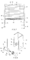
- FIG. 7 is a schematic drawing showing a Venetian blind with concealed lift cords constructed according to a fourth embodiment of the present invention.
- FIG. 8 is an exploded view in an enlarged scale of a part of FIG. 7 showing the structure of the tension adjustment mechanism.
- FIG. 9 is a sectional view taken along line 9 - 9 of FIG. 7 showing the engaged status of the tension adjustment mechanism.
- FIG. 10 is similar to FIG. 9 but showing the tension adjustment mechanism released.
- a Venetian blind 10 comprising a headrail 12 fixedly transversely fastened to the top side of the window W, the headrail 12 having two tension springs 14 bilaterally disposed on the inside in the middle, the tension springs 14 each having an inner end fastened to the inside of the headrail 12 , a bottom rail 16 extended in transverse direction and spaced below the headrail 12 , a number of slats 18 arranged in parallel between the headrail 12 and the bottom rail 16 , a first side track 20 A, a second side track 20 B, a first lift cord 30 A, and a second lift cord 30 B.
- the side tracks 20 A; 20 B are vertically fixedly fastened to the two opposite vertical lateral sides of the window W below the elevation of the headrail 21 and downwardly extended to a position lower than the elevation of the stool of the window W, each comprising a longitudinal sliding groove 22 facing each other.
- the two distal ends of the bottom rail 16 are respectively inserted into the inside the longitudinal sliding grooves 22 of the tracks 20 A; 20 B.
- the lift cords 30 A; 30 B are respectively bilaterally inserted through the slats 18 , each having respective top and bottom ends respectively inserted into the inside of the headrail 12 and the inside of the bottom rail 16 .
- the first ends (top ends) of the lift cord 30 A; 30 B are respectively turned inwards toward the mid point of the headrail 12 and then respectively fixedly connected to the outer ends of the tension springs 14 .
- the second end (bottom end) of the first lift cord 30 A is turned rightwards out of the right end of the bottom rail 16 into the inside of the longitudinal sliding groove 22 of the second side track 20 B and then extended downwards along the longitudinal sliding groove 22 of the second side track 20 B and finally fixedly fastened to the bottom end of the longitudinal sliding groove 22 of the second side track 20 B.
- the second end (bottom end) of the second lift cord 30 B is turned leftwards out of the left end of the bottom rail 16 into the inside of the longitudinal sliding groove 22 of the first side track 20 A and then extended downwards along the longitudinal sliding groove 22 of the first side track 20 A and finally fixedly fastened to the bottom end of the longitudinal sliding groove 22 of the first side track 20 A.
- the tension force of the lift cords 30 A; 30 B hold the bottom rail 16 in position, keeping the Venetian blind 10 in the corresponding extending position.
- the user needs only to directly move the bottom rail 16 with the hand to the desired elevation and then release the hand from the bottom rail 16 .
- the ends of the bottom rail 16 are maintained in the longitudinal sliding grooves 22 of the side tracks 20 A; 20 B (see FIG. 2), preventing oscillation of the blind. Because the bottom rail 16 is confined to the side tracks 20 A; 20 B (the ends of each slat 18 are also respectively inserted into the longitudinal sliding grooves 22 of the side tracks 20 A; 20 B), the blind of the Venetian blind 10 is maintained in vertical and will not swing in the wind.
- the bottom rail 16 can be moved between the upper limit position shown in FIG. 1 where the Venetian blind 10 is fully extended out and the lower limit position shown in FIG. 3 where the Venetian blind 10 is fully received, and positioned in any elevational position between the upper limit position and the lower limit position.
- the second ends (bottom ends) of the lift cords 30 A; 30 B are constantly maintained inside the longitudinal sliding grooves 22 of the side tracks 20 A; 20 B (see FIGS. 3 and 4), i.e., protected within the side tracks 20 A; 20 B. Therefore, the lift cords 30 A; 30 B are kept away from sight and reach of children.
- the first ends (top ends) of the lift cords 30 A; 30 B are respectively connected to the tension springs 14 inside the headrail 12 , providing a tension force to support the bottom rail 16 and, enabling the bottom rail 16 to be moved up and down along the longitudinal sliding grooves 22 of the side tracks 20 A; 20 B.
- the tension springs 14 can be provided near the ends of the headrail 12 with the respective outer ends fixedly fastened to the headrail 12 and the respective inner ends respectively fastened to the first ends (top ends) of the lift cords 30 A; 30 B.
- FIG. 5 shows a Venetian blind 40 with concealed lift cords according to a second embodiment of the present invention.
- the top ends of the lift cords 42 are directly fixedly fastened to the headrail 44 , and the bottom ends of the lift cords 42 are respectively connected to the respective tension springs 46 , which are fixedly provided inside the bottom rail 48 .
- the tension springs 46 may be eliminated if the lift cords are made of elastic material or non-elastic material.
- FIG. 6 shows a Venetian blind with concealed lift cords according to a third embodiment of the present invention.
- the bottom ends of the lift cord 52 ; 56 are respectively bilaterally inserted into the bottom rail 54 and then turned sideways in reversed directions and extended out of the two ends of the bottom rail 54 to the inside of the longitudinal sliding grooves of the side tracks 58 and then extended downwards along the longitudinal sliding grooves of the side tracks 58 and fixedly fastened to the bottom ends the longitudinal sliding grooves of the side tracks 58 respectively.
- the lift cords 52 ; 56 are capable of supporting the bottom rail 54 at the desired elevation between the upper limit position and the lower limit position.
- FIG. 7 shows a Venetian blind with concealed lift cords according to a fourth embodiment of the present invention.
- the Venetian blind 60 is comprised of a headrail 62 fixedly fastened to the top side of the window, a bottom rail 64 disposed in parallel to and spaced below the headrail 62 , a number of slats 66 arranged in parallel between the headrail 62 and the bottom rail 64 , two side tracks 70 vertically fixedly fastened to the two opposite vertical lateral sides of the window, each side track 70 having a longitudinal sliding groove 72 , two tension adjustment mechanisms 80 respectively provided at the bottom ends of the longitudinal sliding grooves 72 of the side tracks 70 , and two lift cords 90 , the lift cords 90 each having a first end respectively fastened to the respective tension springs 92 in the headrail 62 and a bottom end extended downwardly through the slats 66 into the inside of the bottom rail 64 and then extended sideways out of the ends of the bottom rail 64 to the inside of the longitudinal sliding
- each side track 70 comprises a front sidewall 74 and a rear sidewall 75 arranged in parallel, a first pivot hole 76 and a second pivot hole 77 respectively provided in the sidewalls 74 ; 75 , and a plurality of locating holes 78 provided in the rear sidewall 75 and equiangularly spaced around the second pivot hole 77 .
- Each tension adjustment mechanism 80 comprises a bobbin 82 , a knob 88 , and a compression spring 89 .
- the bobbin 82 comprises a body 84 , a front round rod 85 axially extended from the center of one end of the body 84 , a rear round rod 86 axially extended from the center of the other end of the body 84 , and a pin 87 protruded from one end of the body 84 adjacent to the rear round rod 86 .
- the round rods 85 ; 86 are respectively pivotally mounted in the pivot holes 76 ; 77 of the corresponding side track 70 .
- the knob 88 is fastened to the end of the front round rod 85 and disposed outside the corresponding side track 70 .
- the compression spring 89 is mounted on the round rod 85 inside the corresponding side track 70 , having one end stopped at the inner surface of the front sidewall 74 of the corresponding side track 70 and the other end stopped against one end of the body 84 .
- the compression spring 89 imparts a pressure to the bobbin 82 , forcing the bobbin 82 backwardly away from the front sidewall 74 of the corresponding side track 70 toward the rear sidewall 75 .
- the second end of each lift cord 90 is fixedly fastened to the periphery of the body 84 of the bobbin 82 of the corresponding tension adjustment mechanism 80 .
- the compression spring 89 holds the respective bobbin 82 in the rear end position, keeping the pin 87 engaged into one locating hole 78 of the corresponding side track 70 to stop the bobbin 82 from rotary motion relative to the corresponding side track 70 , and therefore the second end of each lift cord 90 is held at the bottom end of the corresponding side track 78 for enabling the tension of the respective lift cord 90 to be maintained at a fixed level to support the bottom rail 64 at the desired elevation.
- the user can pull the knob 88 of each tension adjustment mechanism 80 to disengage the pin 87 of the bobbin 82 of each tension adjustment mechanism 80 from the locating holes 78 , and then drive the knob 88 of each tension adjustment mechanism 80 to rotate the respective bobbin 82 , causing the respective bobbin 82 to wind up the corresponding lift cord 90 (i.e., to adjust the tension of the corresponding lift cord 90 ), and then release the hand from the knob 88 for enabling the corresponding compression spring 89 to force the corresponding bobbin 82 backward into engagement with one locating hole 78 again.
Landscapes
- Engineering & Computer Science (AREA)
- Structural Engineering (AREA)
- Architecture (AREA)
- Civil Engineering (AREA)
- Blinds (AREA)
Abstract
A Venetian blind with concealed lift cords is constructed to include a headrail, a bottom rail, slats, two side tracks vertically fixedly provided at two sides of the window and adapted to guide movement of the bottom rail and the slats, and two lift cords vertically extended through the slats in parallel, each lift cord having a respective top end fastened to the headrail and a respective bottom end inserted into the inside of the bottom rail and respectively extended out of the ends of the bottom rail in reversed directions into the inside of the longitudinal sliding grooves of the side tracks and then turned vertically downwards along the longitudinal sliding grooves and fixedly fastened to bottom end of the longitudinal sliding grooves.
Description
- 1. Field of the Invention
- The present invention relates to Venetian blinds and, more specifically, to a Venetian blind with concealed lift cords that keeps the lift cords from sight and from reach of children.
- 2. Description of the Related Art
- A regular Venetian blind is generally comprised of a top rail, a bottom rail, a plurality of slats arranged in parallel between the top rail and the bottom rail, a lift control mechanism for controlling lifting and positioning of the bottom rail to adjust the extending area of the Venetian blind, and a tilting control mechanism for controlling the tiling angle of the slats to regulate the light. The lift control mechanism comprises a lift cord suspended from the top rail at one side for operation by hand to control the elevation of the bottom rail. Because the lift cord is exposed to the outside, it destroys the sense of beauty of the Venetian blind. Further, because a child can easily reach the exposed lift cord, an accident may occur when a child pulling the lift cord for fun.
- U.S. Pat. No. 6,044,889 disclosed a Venetian blind designed to eliminate the aforesaid problem. This structure of Venetian blind comprises a headrail, a bottom rail, a set of slats, and two lift cords mounted in the headrail. Each lift cord has one end extended downwards through the slats into the inside of the bottom rail and then extended sideways to the outside of the bottom rail, and the other end fastened to a respective bobbin in the wall. When adjusting the extending area of the blind, directly push the bottom rail upwards or pull it downwards to the desired elevation and then release the hand from the bottom rail for enabling the tension of the lift cords to hold the bottom rail in position.
- The aforesaid US patent does not keep the lift cords completely away from sight, i.e., the bottom ends of the lift cords are exposed to the outside. The exposed sections of the lift cords may hook the arm or neck of the person touching the blind accidentally, or may be stretched and damaged by an external moving object.
- It is the main object of the present invention to provide a Venetian blind with concealed lift cords, which can easily be operated to positively control the elevation of the blind without letting the lift cords exposed to the outside.
- It is another object of the present invention to provide a Venetian blind with concealed lift cords, which is safe and durable in use.
- To achieve these objects of the present invention, the Venetian blind comprises a headrail fixedly transversely fastened to the window at a top side; a bottom rail extended in transverse direction and spaced below the headrail; a plurality of slats arranged in parallel between the headrail and the bottom rail; two side tracks respectively fixedly fastened to two opposite lateral sides of the window in vertical, the side tracks each having a longitudinal sliding groove facing each other; and two lift cords extended in parallel through the slats, the lift cords each having a first end fastened to the headrail and a second end downwardly inserted through the slats into the inside of the bottom rail and extended transversely out of two distal ends of the bottom rail in reversed directions into the inside of the longitudinal sliding grooves of the side tracks and then downwardly extended along the longitudinal sliding grooves of the side tracks and fixedly fastened to a respective bottom end of the longitudinal sliding groove of the side tracks.
- FIG. 1 is a schematic drawing of a first embodiment of the present invention, showing the Venetian blind extended out.
- FIG. 2 is a sectional view taken along line 2-2 of FIG. 1.
- FIG. 3 is a schematic drawing corresponding to FIG. 1, showing the blind received.
- FIG. 4 is a sectional view taken along line 4-4 of FIG. 3.
- FIG. 5 is a schematic drawing showing a Venetian blind with concealed lift cords constructed according to a second embodiment of the present invention.
- FIG. 6 is a schematic drawing showing a Venetian blind with concealed lift cords constructed according to a third embodiment of the present invention.
- FIG. 7 is a schematic drawing showing a Venetian blind with concealed lift cords constructed according to a fourth embodiment of the present invention.
- FIG. 8 is an exploded view in an enlarged scale of a part of FIG. 7 showing the structure of the tension adjustment mechanism.
- FIG. 9 is a sectional view taken along line 9-9 of FIG. 7 showing the engaged status of the tension adjustment mechanism.
- FIG. 10 is similar to FIG. 9 but showing the tension adjustment mechanism released.
- Referring to FIGS. from 1 through 4, a Venetian blind 10 is shown comprising a
headrail 12 fixedly transversely fastened to the top side of the window W, theheadrail 12 having twotension springs 14 bilaterally disposed on the inside in the middle, thetension springs 14 each having an inner end fastened to the inside of theheadrail 12, abottom rail 16 extended in transverse direction and spaced below theheadrail 12, a number ofslats 18 arranged in parallel between theheadrail 12 and thebottom rail 16, afirst side track 20A, asecond side track 20B, afirst lift cord 30A, and asecond lift cord 30B. - The
side tracks 20A;20B are vertically fixedly fastened to the two opposite vertical lateral sides of the window W below the elevation of theheadrail 21 and downwardly extended to a position lower than the elevation of the stool of the window W, each comprising a longitudinalsliding groove 22 facing each other. The two distal ends of thebottom rail 16 are respectively inserted into the inside the longitudinalsliding grooves 22 of thetracks 20A;20B. Thelift cords 30A;30B are respectively bilaterally inserted through theslats 18, each having respective top and bottom ends respectively inserted into the inside of theheadrail 12 and the inside of thebottom rail 16. After inserted into the inside of theheadrail 12, the first ends (top ends) of thelift cord 30A;30B are respectively turned inwards toward the mid point of theheadrail 12 and then respectively fixedly connected to the outer ends of thetension springs 14. After inserted into the inside of thebottom rail 16, the second end (bottom end) of thefirst lift cord 30A is turned rightwards out of the right end of thebottom rail 16 into the inside of the longitudinalsliding groove 22 of thesecond side track 20B and then extended downwards along the longitudinal slidinggroove 22 of thesecond side track 20B and finally fixedly fastened to the bottom end of the longitudinal slidinggroove 22 of thesecond side track 20B. After inserted into the inside of thebottom rail 16, the second end (bottom end) of thesecond lift cord 30B is turned leftwards out of the left end of thebottom rail 16 into the inside of the longitudinalsliding groove 22 of thefirst side track 20A and then extended downwards along the longitudinalsliding groove 22 of thefirst side track 20A and finally fixedly fastened to the bottom end of the longitudinal slidinggroove 22 of thefirst side track 20A. - By means of the aforesaid structure arrangement (the tilting control mechanism of the Venetian blind is of the known art and not within the scope of the claims of the present invention, no further detailed description on the tilting control mechanism is necessary), the tension force of the
lift cords 30A;30B hold thebottom rail 16 in position, keeping the Venetian blind 10 in the corresponding extending position. When adjusting the elevation of the blind, the user needs only to directly move thebottom rail 16 with the hand to the desired elevation and then release the hand from thebottom rail 16. - During lifting, the ends of the
bottom rail 16 are maintained in the longitudinalsliding grooves 22 of theside tracks 20A;20B (see FIG. 2), preventing oscillation of the blind. Because thebottom rail 16 is confined to theside tracks 20A;20B (the ends of eachslat 18 are also respectively inserted into the longitudinal slidinggrooves 22 of theside tracks 20A;20B), the blind of the Venetian blind 10 is maintained in vertical and will not swing in the wind. - During lifting, the
bottom rail 16 can be moved between the upper limit position shown in FIG. 1 where the Venetian blind 10 is fully extended out and the lower limit position shown in FIG. 3 where the Venetian blind 10 is fully received, and positioned in any elevational position between the upper limit position and the lower limit position. When thebottom rail 16 positioned in any elevational position, the second ends (bottom ends) of thelift cords 30A;30B are constantly maintained inside the longitudinalsliding grooves 22 of theside tracks 20A;20B (see FIGS. 3 and 4), i.e., protected within theside tracks 20A;20B. Therefore, thelift cords 30A;30B are kept away from sight and reach of children. - In the aforesaid first embodiment of the present invention, the first ends (top ends) of the
lift cords 30A;30B are respectively connected to thetension springs 14 inside theheadrail 12, providing a tension force to support thebottom rail 16 and, enabling thebottom rail 16 to be moved up and down along the longitudinalsliding grooves 22 of theside tracks 20A;20B. Alternatively, thetension springs 14 can be provided near the ends of theheadrail 12 with the respective outer ends fixedly fastened to theheadrail 12 and the respective inner ends respectively fastened to the first ends (top ends) of thelift cords 30A;30B. - FIG. 5 shows a Venetian blind 40 with concealed lift cords according to a second embodiment of the present invention. According to this embodiment, the top ends of the
lift cords 42 are directly fixedly fastened to theheadrail 44, and the bottom ends of thelift cords 42 are respectively connected to therespective tension springs 46, which are fixedly provided inside thebottom rail 48. Thetension springs 46 may be eliminated if the lift cords are made of elastic material or non-elastic material. - FIG. 6 shows a Venetian blind with concealed lift cords according to a third embodiment of the present invention. According to this embodiment, the bottom ends of the
lift cord 52;56 are respectively bilaterally inserted into thebottom rail 54 and then turned sideways in reversed directions and extended out of the two ends of thebottom rail 54 to the inside of the longitudinal sliding grooves of theside tracks 58 and then extended downwards along the longitudinal sliding grooves of theside tracks 58 and fixedly fastened to the bottom ends the longitudinal sliding grooves of theside tracks 58 respectively. According to this arrangement, thelift cords 52;56 are capable of supporting thebottom rail 54 at the desired elevation between the upper limit position and the lower limit position. - FIG. 7 shows a Venetian blind with concealed lift cords according to a fourth embodiment of the present invention. According to this embodiment, the Venetian blind 60 is comprised of a
headrail 62 fixedly fastened to the top side of the window, abottom rail 64 disposed in parallel to and spaced below theheadrail 62, a number ofslats 66 arranged in parallel between theheadrail 62 and thebottom rail 64, twoside tracks 70 vertically fixedly fastened to the two opposite vertical lateral sides of the window, eachside track 70 having a longitudinal slidinggroove 72, twotension adjustment mechanisms 80 respectively provided at the bottom ends of the longitudinalsliding grooves 72 of theside tracks 70, and twolift cords 90, thelift cords 90 each having a first end respectively fastened to therespective tension springs 92 in theheadrail 62 and a bottom end extended downwardly through theslats 66 into the inside of thebottom rail 64 and then extended sideways out of the ends of thebottom rail 64 to the inside of the longitudinalsliding grooves 72 of theside tracks 70 and then extended downwards along the longitudinalsliding grooves 72 of theside tracks 70 and connected to thetension adjustment mechanisms 80 respectively. - Referring to FIGS. from 8 through 10 and FIG. 7 again, each
side track 70 comprises afront sidewall 74 and arear sidewall 75 arranged in parallel, afirst pivot hole 76 and asecond pivot hole 77 respectively provided in thesidewalls 74;75, and a plurality of locatingholes 78 provided in therear sidewall 75 and equiangularly spaced around thesecond pivot hole 77. Eachtension adjustment mechanism 80 comprises abobbin 82, aknob 88, and acompression spring 89. Thebobbin 82 comprises abody 84, afront round rod 85 axially extended from the center of one end of thebody 84, arear round rod 86 axially extended from the center of the other end of thebody 84, and apin 87 protruded from one end of thebody 84 adjacent to therear round rod 86. Theround rods 85;86 are respectively pivotally mounted in thepivot holes 76;77 of thecorresponding side track 70. Theknob 88 is fastened to the end of thefront round rod 85 and disposed outside thecorresponding side track 70. Thecompression spring 89 is mounted on theround rod 85 inside thecorresponding side track 70, having one end stopped at the inner surface of thefront sidewall 74 of thecorresponding side track 70 and the other end stopped against one end of thebody 84. Thecompression spring 89 imparts a pressure to thebobbin 82, forcing thebobbin 82 backwardly away from thefront sidewall 74 of thecorresponding side track 70 toward therear sidewall 75. The second end of eachlift cord 90 is fixedly fastened to the periphery of thebody 84 of thebobbin 82 of the correspondingtension adjustment mechanism 80. - Referring to FIG. 9, normally, the
compression spring 89 holds therespective bobbin 82 in the rear end position, keeping thepin 87 engaged into one locatinghole 78 of thecorresponding side track 70 to stop thebobbin 82 from rotary motion relative to thecorresponding side track 70, and therefore the second end of eachlift cord 90 is held at the bottom end of thecorresponding side track 78 for enabling the tension of therespective lift cord 90 to be maintained at a fixed level to support thebottom rail 64 at the desired elevation. In case the tension springs 92 start to wear due to long uses and the tension force of thelift cords 90 becomes insufficient, the user can pull theknob 88 of eachtension adjustment mechanism 80 to disengage thepin 87 of thebobbin 82 of eachtension adjustment mechanism 80 from the locating holes 78, and then drive theknob 88 of eachtension adjustment mechanism 80 to rotate therespective bobbin 82, causing therespective bobbin 82 to wind up the corresponding lift cord 90 (i.e., to adjust the tension of the corresponding lift cord 90), and then release the hand from theknob 88 for enabling the correspondingcompression spring 89 to force the correspondingbobbin 82 backward into engagement with one locatinghole 78 again.
Claims (8)
1. A Venetian blind installed in a window and adapted for regulating light, comprising:
a headrail fixedly transversely fastened to said window at a top side;
a bottom rail extended in transverse direction and spaced below said headrail;
a plurality of slats arranged in parallel between said headrail and said bottom rail;
two side tracks respectively fixedly fastened to two opposite lateral sides of said window in vertical, said side tracks each having a longitudinal sliding groove facing each other; and
two lift cords extended in parallel through said slats, said lift cords each having a first end fastened to said headrail and a second end downwardly inserted through said slats into the inside of said bottom rail and extended transversely out of two distal ends of said bottom rail in reversed directions into the inside of the longitudinal sliding grooves of said side tracks and then downwardly extended along the longitudinal sliding grooves of said side tracks and fixedly fastened to a respective bottom end of said longitudinal sliding groove of said side tracks.
2. The Venetian blind as claimed in claim 1 , further comprising two tension springs respectively mounted inside said headrail, said tension springs each having one end fixedly fastened to said headrail and an opposite end respectively connected to the first ends of said lift cords to secure said lift cords to said headrail.
3. The Venetian blind as claimed in claim 2 , wherein said side tracks each comprise a tension adjustment mechanism disposed in a bottom end of the respective longitudinal sliding groove and connected to the second end of one of said lift cords and adapted for adjusting the tension of the corresponding lift cord.
4. The Venetian blind as claimed in claim 3 , wherein said side tracks each comprise a front pivot hole, a rear pivot hole in alignment with said front pivot hole, and a plurality of locating holes equiangularly spaced around said rear pivot hole; the tension adjustment mechanism of each of said side tracks comprises a bobbin fixedly fastened the second end of the corresponding lift cord and adapted for winding up the corresponding lift cord to adjust the tension of the corresponding lift cord, said bobbin comprising a bobbin body, said bobbin body having a front end and a rear end, a front round rod axially extended from the center of the front end of said bobbin body and pivotally mounted in the front pivot hole of the corresponding side track, a rear round rod axially extended from the center of the rear end of said bobbin body and pivotally inserted into the rear pivot hole of the corresponding side track, and a pin protruded from the rear end of said bobbin body and adapted for engaging into one locating hole of the corresponding side track to stop said bobbin from rotary motion relative to the corresponding side track, a knob fastened to an outer end of said front round rod of said bobbin outside the corresponding side track and adapted for moving said bobbin to disengage said pin from the locating holes of the corresponding side track for enabling said bobbins to be rotated to wind up the corresponding lift cord, and a compression spring mounted on said front round rod inside the corresponding side track and stopped between the front end of said bobbin body and an inner surface of the front sidewall of the corresponding side track to force said pin into engagement with one locating hole of the corresponding side track.
5. The Venetian blind as claimed in claim 1 , wherein further comprising two tension springs respectively fastened to a bottom end of the longitudinal sliding groove of each of said side tracks, said tension springs each having one end fixedly fastened to the longitudinal sliding groove of one of said side tracks and an opposite end connected to the second end of one of said lift cords.
6. The Venetian blind as claimed in claim 1 , said lift cords include a first lift cord disposed at the left side and a second lift cord disposed at the right side; said side tracks include a first side track disposed at the left side and a second side track disposed at the right side; the second end of said first lift cord is extended rightwards along said bottom rail to the outside of a right end of said bottom rail into the inside of the longitudinal sliding groove of said second side track and then fixedly fastened to the bottom end of the longitudinal sliding groove of said second side track; the second end of said second lift cord is extended leftwards along said bottom rail to the outside of a left end of said bottom rail into the inside of the longitudinal sliding groove of said first side track and then fixedly fastened to the bottom end of the longitudinal sliding groove of said first side track.
7. The Venetian blind as claimed in claim 1 , wherein said lift cords include a first lift cord disposed at the left side and a second lift cord disposed at the right side; said side tracks include a first side track disposed at the left side and a second side track disposed at the right side; the second end of said first lift cord is extended leftwards to the outside of a left end of said bottom rail into the inside of the longitudinal sliding groove of said first side track and then fixedly fastened to the bottom end of the longitudinal sliding groove of said first side track; the second end of said second lift cord is extended rightwards to the outside of a right end of said bottom rail into the inside of the longitudinal sliding groove of said second side track and then fixedly fastened to the bottom end of the longitudinal sliding groove of said second side track.
8. The Venetian blind as claimed in claim 1 , wherein said bottom rail has two distal ends respectively suspended in the longitudinal sliding grooves of said side tracks.
Applications Claiming Priority (2)
| Application Number | Priority Date | Filing Date | Title |
|---|---|---|---|
| TW091204732U TW521793U (en) | 2002-04-11 | 2002-04-11 | Venetian blind with hidden pulling cords |
| TW91204732 | 2002-04-11 |
Publications (1)
| Publication Number | Publication Date |
|---|---|
| US20030192653A1 true US20030192653A1 (en) | 2003-10-16 |
Family
ID=28038174
Family Applications (1)
| Application Number | Title | Priority Date | Filing Date |
|---|---|---|---|
| US10/162,647 Abandoned US20030192653A1 (en) | 2002-04-11 | 2002-06-06 | Venetian blind with concealed lift cords |
Country Status (3)
| Country | Link |
|---|---|
| US (1) | US20030192653A1 (en) |
| CA (1) | CA2388897A1 (en) |
| TW (1) | TW521793U (en) |
Cited By (9)
| Publication number | Priority date | Publication date | Assignee | Title |
|---|---|---|---|---|
| US20040149398A1 (en) * | 2003-01-23 | 2004-08-05 | Shih-Ming Lin | Window blind having a restrainable bottom rail |
| US20080121350A1 (en) * | 2006-09-19 | 2008-05-29 | Li-Ming Cheng | Window covering with spring-assisted roll-up devices at upper and lower rails |
| US20140138036A1 (en) * | 2012-11-22 | 2014-05-22 | Ruben H. J. de Vries | Tensioned venetian blind system |
| US8857494B2 (en) * | 2012-06-18 | 2014-10-14 | Lutron Electronics Co., Inc. | Window treatment having an adjustable bottom bar |
| US9057219B1 (en) | 2011-08-30 | 2015-06-16 | Newell Window Furnishings, Inc. | Window covering with integrated side track |
| US20160340976A1 (en) * | 2014-07-31 | 2016-11-24 | Nien Made Enterprise Co., Ltd. | Adjustable cord locker and window blind having such adjustable cord locker |
| US20190162018A1 (en) * | 2017-11-28 | 2019-05-30 | Po-Yu Chen | Resistance adjusting device for non-pull cord window blind |
| US20190162278A1 (en) * | 2017-11-28 | 2019-05-30 | Po-Yu Chen | Resistance adjusting device for non-pull cord window blind |
| US10995545B2 (en) * | 2018-04-24 | 2021-05-04 | Po-Yu Chen | Multistate resistance adjusting device for non-pull cord window blind |
-
2002
- 2002-04-11 TW TW091204732U patent/TW521793U/en unknown
- 2002-06-04 CA CA002388897A patent/CA2388897A1/en not_active Abandoned
- 2002-06-06 US US10/162,647 patent/US20030192653A1/en not_active Abandoned
Cited By (14)
| Publication number | Priority date | Publication date | Assignee | Title |
|---|---|---|---|---|
| US20040149398A1 (en) * | 2003-01-23 | 2004-08-05 | Shih-Ming Lin | Window blind having a restrainable bottom rail |
| US6802356B2 (en) * | 2003-01-23 | 2004-10-12 | Shih-Ming Lin | Window blind having a restrainable bottom rail |
| US20080121350A1 (en) * | 2006-09-19 | 2008-05-29 | Li-Ming Cheng | Window covering with spring-assisted roll-up devices at upper and lower rails |
| US9057219B1 (en) | 2011-08-30 | 2015-06-16 | Newell Window Furnishings, Inc. | Window covering with integrated side track |
| US8857494B2 (en) * | 2012-06-18 | 2014-10-14 | Lutron Electronics Co., Inc. | Window treatment having an adjustable bottom bar |
| US20140138036A1 (en) * | 2012-11-22 | 2014-05-22 | Ruben H. J. de Vries | Tensioned venetian blind system |
| US20160340976A1 (en) * | 2014-07-31 | 2016-11-24 | Nien Made Enterprise Co., Ltd. | Adjustable cord locker and window blind having such adjustable cord locker |
| US20190162018A1 (en) * | 2017-11-28 | 2019-05-30 | Po-Yu Chen | Resistance adjusting device for non-pull cord window blind |
| US20190162017A1 (en) * | 2017-11-28 | 2019-05-30 | Po-Yu Chen | Resistance adjusting device for non-pull cord window blind |
| US20190162278A1 (en) * | 2017-11-28 | 2019-05-30 | Po-Yu Chen | Resistance adjusting device for non-pull cord window blind |
| US10704323B2 (en) * | 2017-11-28 | 2020-07-07 | Po-Yu Chen | Resistance adjusting device for non-pull cord window blind |
| US10704658B2 (en) * | 2017-11-28 | 2020-07-07 | Po-Yu Chen | Resistance adjusting device for non-pull cord window blind |
| US10774582B2 (en) * | 2017-11-28 | 2020-09-15 | Po-Yu Chen | Resistance adjusting device for non-pull cord window blind |
| US10995545B2 (en) * | 2018-04-24 | 2021-05-04 | Po-Yu Chen | Multistate resistance adjusting device for non-pull cord window blind |
Also Published As
| Publication number | Publication date |
|---|---|
| TW521793U (en) | 2003-02-21 |
| CA2388897A1 (en) | 2003-10-11 |
Similar Documents
| Publication | Publication Date | Title |
|---|---|---|
| CA2390484C (en) | Venetian blind that keeps lift cords concealed | |
| US5465775A (en) | Venetian blind with wand operator | |
| CA2475716C (en) | Fabric window blind | |
| CA2409802C (en) | Combination blind with multiple shading sections | |
| US6575223B1 (en) | Concealed type lifting control mechanism for venetian blind | |
| US8708023B2 (en) | Cordless blind assembly | |
| US20090120592A1 (en) | Control unit for lift system for coverings for architectural openings | |
| US6662850B2 (en) | Lift coard concealable venetian blind lift control mechanism | |
| US6619365B1 (en) | Plug-in transmission mechanism for a motor-driven blind | |
| US20170138123A1 (en) | Window blind | |
| US20030201076A1 (en) | Venetian blind with concealed lift cords | |
| US20030192653A1 (en) | Venetian blind with concealed lift cords | |
| CA2410834C (en) | Vertical retractable blind | |
| CA2409966C (en) | Venetian blind that keeps lift cords concealed | |
| US6397918B1 (en) | Venetian blind | |
| CA2428561A1 (en) | Window blind assembly control crank gear | |
| JP6670540B2 (en) | Horizontal blinds | |
| US20040003900A1 (en) | Venetian blind having lift cords kept from sight | |
| WO2014131022A1 (en) | System for pivoting a blind slat | |
| US6691760B1 (en) | Lift cord tensioning device | |
| EP1416115A1 (en) | Combination blind with multiple shading sections | |
| KR101422999B1 (en) | Roll blind apparatus of free-fall slim type for prevention of child's accident | |
| EP1577484A2 (en) | Fabric window blind | |
| AU2002301952B2 (en) | Vertical Retractable Blind | |
| JP2016142020A (en) | Horizontal blind |
Legal Events
| Date | Code | Title | Description |
|---|---|---|---|
| AS | Assignment |
Owner name: NIEN MADE ENTERPRISE CO., LTD., TAIWAN Free format text: ASSIGNMENT OF ASSIGNORS INTEREST;ASSIGNOR:NIEN, MING;REEL/FRAME:012968/0447 Effective date: 20020526 |
|
| STCB | Information on status: application discontinuation |
Free format text: ABANDONED -- FAILURE TO RESPOND TO AN OFFICE ACTION |