US20030192594A1 - Silent-operating device for feeding water into a tank, in particular for filling a lavatory flush tank - Google Patents
Silent-operating device for feeding water into a tank, in particular for filling a lavatory flush tank Download PDFInfo
- Publication number
- US20030192594A1 US20030192594A1 US10/321,435 US32143502A US2003192594A1 US 20030192594 A1 US20030192594 A1 US 20030192594A1 US 32143502 A US32143502 A US 32143502A US 2003192594 A1 US2003192594 A1 US 2003192594A1
- Authority
- US
- United States
- Prior art keywords
- members
- chamber
- holes
- tank
- consecutive
- Prior art date
- Legal status (The legal status is an assumption and is not a legal conclusion. Google has not performed a legal analysis and makes no representation as to the accuracy of the status listed.)
- Granted
Links
- XLYOFNOQVPJJNP-UHFFFAOYSA-N water Substances O XLYOFNOQVPJJNP-UHFFFAOYSA-N 0.000 title claims abstract description 21
- 238000004804 winding Methods 0.000 claims abstract description 5
- 125000006850 spacer group Chemical group 0.000 claims description 4
- 230000002093 peripheral effect Effects 0.000 claims description 3
- 230000000284 resting effect Effects 0.000 claims 1
- 230000001743 silencing effect Effects 0.000 abstract 1
- 239000007787 solid Substances 0.000 description 2
- 230000008878 coupling Effects 0.000 description 1
- 238000010168 coupling process Methods 0.000 description 1
- 238000005859 coupling reaction Methods 0.000 description 1
- 238000011010 flushing procedure Methods 0.000 description 1
- 238000004519 manufacturing process Methods 0.000 description 1
- 238000007789 sealing Methods 0.000 description 1
- 230000001052 transient effect Effects 0.000 description 1
- 238000011144 upstream manufacturing Methods 0.000 description 1
Images


Classifications
-
- E—FIXED CONSTRUCTIONS
- E03—WATER SUPPLY; SEWERAGE
- E03D—WATER-CLOSETS OR URINALS WITH FLUSHING DEVICES; FLUSHING VALVES THEREFOR
- E03D1/00—Water flushing devices with cisterns ; Setting up a range of flushing devices or water-closets; Combinations of several flushing devices
- E03D1/30—Valves for high or low level cisterns; Their arrangement ; Flushing mechanisms in the cistern, optionally with provisions for a pre-or a post- flushing and for cutting off the flushing mechanism in case of leakage
- E03D1/32—Arrangement of inlet valves
-
- E—FIXED CONSTRUCTIONS
- E03—WATER SUPPLY; SEWERAGE
- E03D—WATER-CLOSETS OR URINALS WITH FLUSHING DEVICES; FLUSHING VALVES THEREFOR
- E03D9/00—Sanitary or other accessories for lavatories ; Devices for cleaning or disinfecting the toilet room or the toilet bowl; Devices for eliminating smells
- E03D9/14—Noise-reducing means combined with flushing valves
-
- Y—GENERAL TAGGING OF NEW TECHNOLOGICAL DEVELOPMENTS; GENERAL TAGGING OF CROSS-SECTIONAL TECHNOLOGIES SPANNING OVER SEVERAL SECTIONS OF THE IPC; TECHNICAL SUBJECTS COVERED BY FORMER USPC CROSS-REFERENCE ART COLLECTIONS [XRACs] AND DIGESTS
- Y10—TECHNICAL SUBJECTS COVERED BY FORMER USPC
- Y10T—TECHNICAL SUBJECTS COVERED BY FORMER US CLASSIFICATION
- Y10T137/00—Fluid handling
- Y10T137/7287—Liquid level responsive or maintaining systems
- Y10T137/7358—By float controlled valve
Definitions
- the present invention relates to a silent-operating device for feeding water into a tank, in particular for filling a lavatory flush tank.
- European Patent Application EP-A-424274 provides for reducing noise by circulating the water in a chamber filled with solid spheroidal bodies. Though fairly effective, this solution still leaves room for further improvement in terms of noise reduction, besides posing manufacturing problems (mainly owing to the necessity of producing and inserting the solid bodies into the chamber).
- a silent-operating device for feeding water into a tank, in particular for filling a lavatory flush tank, comprising a chamber for the passage of a flow of water; said chamber housing flow deflecting members, and comprising an inlet and an outlet defining a flow direction; and the device being characterized in that said members are perforated members arranged successively and spaced apart substantially in said flow direction.
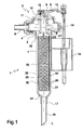
- FIG. 1 shows a longitudinal section of a feed device in accordance with the invention
- FIG. 2 shows an exploded view in perspective of a number of component parts of the FIG. 1 device
- FIG. 3 shows a plan view of two of the component parts in FIG. 2;
- FIG. 4 shows a plan view of an optional component part of the FIG. 1 device
- FIG. 5 shows an exploded view in perspective of an alternative embodiment of the FIG. 2 component parts.
- Number 1 in FIG. 1 indicates as a whole a silent-operating feed device for a flush tank (not shown).
- Device 1 comprises a body 2 housing a valve assembly 3 interposed between an inlet channel 4 and an outlet channel 5 .
- Inlet channel 4 is connected to a fitting 6 for connection to the water mains, and outlet channel 5 is connected to an outflow pipe 7 having an axis substantially perpendicular to inlet channel 4 and, in use, substantially vertical.
- valve assembly 3 is a known diaphragm valve assembly, and therefore not described or illustrated in detail.
- valve assembly 3 comprises a disk-shaped diaphragm 8 separating inlet channel 4 from outlet channel 5 and closing a counterpressure chamber 9 ;
- counterpressure chamber 9 has a relief hole 10 , and communicates with inlet channel 4 via a small-section nozzle 11 through diaphragm 8 ;
- a shutter 12 controlled by a lever 13 connected to a float 15 by an adjustable rod 14 , selectively opens and closes relief hole 10 ;
- diaphragm 8 is elastically deformable to allow water to flow from inlet channel 4 to outlet channel 5 when relief hole 10 is open.
- Outflow pipe 7 has an end 16 for connection to body 2 (and having, for example, a threaded coupling and sealing rings); and a free end 17 opposite end 16 and possibly connected to a tubular extension 18 .
- Outflow pipe 7 is provided internally with a chamber 20 for passage of the flow of water from outlet channel 5 .
- Chamber 20 which for example is cylindrical, comprises an inlet 21 and an outlet 22 located respectively at ends 16 and 17 of outflow pipe 7 , and defining a water flow direction indicated schematically in FIG. 1 by arrow 23 and coincident, in the example shown, with a longitudinal axis L of chamber 20 .
- Chamber 20 houses a number of perforated flow deflecting members 25 comprising respective numbers of through holes 26 , and which are positioned transversely inside chamber 20 , and are arranged successively and spaced apart substantially in the water flow direction 23 inside chamber 20 , i.e. along axis L.
- each member 25 comprises a flat perforated plate 27 positioned substantially perpendicular to axis L and in the form of a circular disk with a diameter substantially equal to the inside diameter of chamber 20 .
- Holes 26 are substantially parallel to axis L, and the holes 26 of consecutive members 25 (e.g. members 25 a , 25 b in FIGS. 2 and 3) are offset to define, inside chamber 20 , a labyrinth water flow path comprising a large number of winding coil-like or zigzag water flow paths.
- holes 26 may obviously be varied in numerous ways, while still defining a labyrinth water flow path. More specifically, a winding coil-like or zigzag path may also be obtained using members 25 , each with only one hole 26 , providing the holes 26 of consecutive members 25 are offset. What is shown and described herein is therefore to be considered purely as a non-limiting example.
- each member 25 has a number of holes 26 spaced in the form of a triangle and symmetric with respect to a geometric centre 28 of member 25 .
- Consecutive members 25 a , 25 b have the same arrangement of respective holes 26 , but are turned 180° with respect to each other.
- aligning means are provided to set each member 25 in a predetermined position with respect to the other members 25 and to flow direction 23 , and circumferential connecting members are provided for connecting members 25 circumferentially to chamber 20 .
- each member 25 has a groove 31 formed in a predetermined position on a peripheral edge 32 of respective plate 27 ; a longitudinal guide 33 parallel to axis L is provided inside chamber 20 to engage grooves 31 ; and members 25 are separated by substantially ring-shaped spacers 35 stacked alternately with members 25 and having respective grooves 36 cooperating with guide 33 .
- members 25 are equally spaced along axis L, and plates 27 are all the same thickness. It is understood, however, that both the spacing of members 25 and the thickness of plates 27 may vary in flow direction 23 .
- holes 26 of each member 25 are all of the same diameter.
- the holes 26 of consecutive members 25 may differ in diameter, and preferably get smaller in diameter in flow direction 23 inside chamber 20 .
- Holes 26 of each member 25 may also be arranged randomly, as opposed to regularly as described above, providing the randomly arranged holes 26 of consecutive members 25 are offset.
- FIG. 4 shows an optional member 25 c , which may, for example, be used as the first member in the succession of members 25 , and which has through holes 26 larger in diameter than holes 26 of succeeding members 25 , spaced in the form of a hexagon, and centrally symmetric about axis L.
- members 25 again comprise respective substantially flat, circular, perforated plates 27 , but spacers 35 are carried integrally in one piece with plates 27 , and are defined by respective projecting peripheral collars 37 of members 25 .
- Collars 37 project axially on both sides of respective plates 27 , but may obviously also project from one side only.
- Each collar 37 has two diametrically opposite axial projections 38 of different cross sections (e.g. a substantially rectangular-section projection 38 a , and a substantially circular-section projection 38 b ); and two seats 39 , each of the same shape as a corresponding projection 38 .
- Projections 38 of each member 25 are inserted inside seats 39 on the succeeding member to align members 25 with respect to one another and connect each member 25 circumferentially to the succeeding member.
- valve assembly 3 controlled by float 15 , is opened, as known, to fill the tank, water flows into chamber 20 through inlet 21 , and down through chamber 20 substantially in flow direction 23 . Before flowing out through outlet 22 , the water flows down chamber 20 through holes 26 , and therefore along the labyrinth path (i.e. a number of winding coil-like or zigzag paths) defined by members 25 , thus significantly reducing the noise level when filling the tank, as confirmed by tests.
- labyrinth path i.e. a number of winding coil-like or zigzag paths
- the water inside chamber 20 may be circulated upwards, as opposed to downwards as described above.
- chamber 20 may be located upstream, as opposed to downstream, from valve assembly 3 , as illustrated for example in EP-A-42427, so that chamber 20 and members 25 also dampen the vibration induced by the transient state when closing valve assembly 3 , thus further reducing the overall noise level.
- changes may be made to the spacing of members 25 , the arrangement, shape and/or size of holes 26 , and the thickness of plates 27 .
Landscapes
- Health & Medical Sciences (AREA)
- Public Health (AREA)
- Life Sciences & Earth Sciences (AREA)
- Engineering & Computer Science (AREA)
- Hydrology & Water Resources (AREA)
- Water Supply & Treatment (AREA)
- Epidemiology (AREA)
- Details Of Valves (AREA)
- Sanitary Device For Flush Toilet (AREA)
- Filling Of Jars Or Cans And Processes For Cleaning And Sealing Jars (AREA)
- Bidet-Like Cleaning Device And Other Flush Toilet Accessories (AREA)
- Filling Or Discharging Of Gas Storage Vessels (AREA)
- Washing And Drying Of Tableware (AREA)
- Cleaning By Liquid Or Steam (AREA)
Abstract
There is provided a silent-operating device for feeding water into a tank, in particular for filling a lavatory flush tank; the silencing effect is achieved by feeding the water through a chamber housing flow deflecting members; the members are perforated members arranged successively and spaced apart in the flow direction inside the chamber, and have respective numbers of through holes; the holes of consecutive members being offset with respect to one another to define a labyrinth path, i.e. a number of winding coil-like or zigzag paths, inside the chamber.
Description
- The present invention relates to a silent-operating device for feeding water into a tank, in particular for filling a lavatory flush tank.
- As is known, filling a lavatory flush tank after each flushing operation generates sound vibration which is preferably eliminated or at least reduced.
- Various types of flush tank feed devices designed to reduce noise are known.
- For example, European Patent Application EP-A-424274 provides for reducing noise by circulating the water in a chamber filled with solid spheroidal bodies. Though fairly effective, this solution still leaves room for further improvement in terms of noise reduction, besides posing manufacturing problems (mainly owing to the necessity of producing and inserting the solid bodies into the chamber).
- It is an object of the present invention to provide a water feed device which, as compared with known solutions, is fully effective in reducing noise, and at the same time is cheap and easy to produce.
- According to the present invention, there is provided a silent-operating device for feeding water into a tank, in particular for filling a lavatory flush tank, comprising a chamber for the passage of a flow of water; said chamber housing flow deflecting members, and comprising an inlet and an outlet defining a flow direction; and the device being characterized in that said members are perforated members arranged successively and spaced apart substantially in said flow direction.
- In addition to being cheap and easy to produce, tests have shown the device according to the present invention to be also fully effective in terms of noise reduction.
- A number of non-limiting embodiments of the present invention will be described by way of example with reference to the accompanying drawings, in which:
- FIG. 1 shows a longitudinal section of a feed device in accordance with the invention;
- FIG. 2 shows an exploded view in perspective of a number of component parts of the FIG. 1 device;
- FIG. 3 shows a plan view of two of the component parts in FIG. 2;
- FIG. 4 shows a plan view of an optional component part of the FIG. 1 device;
- FIG. 5 shows an exploded view in perspective of an alternative embodiment of the FIG. 2 component parts.
-
Number 1 in FIG. 1 indicates as a whole a silent-operating feed device for a flush tank (not shown).Device 1 comprises abody 2 housing avalve assembly 3 interposed between aninlet channel 4 and an outlet channel 5.Inlet channel 4 is connected to afitting 6 for connection to the water mains, and outlet channel 5 is connected to anoutflow pipe 7 having an axis substantially perpendicular to inletchannel 4 and, in use, substantially vertical. - In the non-limiting example shown in FIG. 1,
valve assembly 3 is a known diaphragm valve assembly, and therefore not described or illustrated in detail. Briefly,valve assembly 3 comprises a disk-shaped diaphragm 8 separatinginlet channel 4 from outlet channel 5 and closing acounterpressure chamber 9;counterpressure chamber 9 has arelief hole 10, and communicates withinlet channel 4 via a small-section nozzle 11 throughdiaphragm 8; ashutter 12, controlled by alever 13 connected to afloat 15 by anadjustable rod 14, selectively opens and closesrelief hole 10; anddiaphragm 8 is elastically deformable to allow water to flow frominlet channel 4 to outlet channel 5 whenrelief hole 10 is open. -
Outflow pipe 7 has anend 16 for connection to body 2 (and having, for example, a threaded coupling and sealing rings); and afree end 17opposite end 16 and possibly connected to atubular extension 18. -
Outflow pipe 7 is provided internally with achamber 20 for passage of the flow of water from outlet channel 5.Chamber 20, which for example is cylindrical, comprises aninlet 21 and anoutlet 22 located respectively atends outflow pipe 7, and defining a water flow direction indicated schematically in FIG. 1 byarrow 23 and coincident, in the example shown, with a longitudinal axis L ofchamber 20. -
Chamber 20 houses a number of perforatedflow deflecting members 25 comprising respective numbers of throughholes 26, and which are positioned transversely insidechamber 20, and are arranged successively and spaced apart substantially in thewater flow direction 23 insidechamber 20, i.e. along axis L. - With reference also to FIGS. 2 and 3, each
member 25 comprises a flatperforated plate 27 positioned substantially perpendicular to axis L and in the form of a circular disk with a diameter substantially equal to the inside diameter ofchamber 20.Holes 26 are substantially parallel to axis L, and theholes 26 of consecutive members 25 (e.g. members chamber 20, a labyrinth water flow path comprising a large number of winding coil-like or zigzag water flow paths. - The shape, size, and arrangement of
holes 26 may obviously be varied in numerous ways, while still defining a labyrinth water flow path. More specifically, a winding coil-like or zigzag path may also be obtained usingmembers 25, each with only onehole 26, providing theholes 26 ofconsecutive members 25 are offset. What is shown and described herein is therefore to be considered purely as a non-limiting example. - In the embodiment shown purely by way of a non-limiting example, each
member 25 has a number ofholes 26 spaced in the form of a triangle and symmetric with respect to ageometric centre 28 ofmember 25.Consecutive members respective holes 26, but are turned 180° with respect to each other. To insert and retainmembers 25 in the desired pattern insidechamber 20, aligning means are provided to set eachmember 25 in a predetermined position with respect to theother members 25 and to flowdirection 23, and circumferential connecting members are provided for connectingmembers 25 circumferentially tochamber 20. - In the example shown, each
member 25 has agroove 31 formed in a predetermined position on aperipheral edge 32 ofrespective plate 27; alongitudinal guide 33 parallel to axis L is provided insidechamber 20 to engagegrooves 31; andmembers 25 are separated by substantially ring-shaped spacers 35 stacked alternately withmembers 25 and havingrespective grooves 36 cooperating withguide 33. - In the FIG. 1 embodiment,
members 25 are equally spaced along axis L, andplates 27 are all the same thickness. It is understood, however, that both the spacing ofmembers 25 and the thickness ofplates 27 may vary inflow direction 23. - Preferably, though not necessarily,
holes 26 of eachmember 25 are all of the same diameter. Theholes 26 ofconsecutive members 25, however, may differ in diameter, and preferably get smaller in diameter inflow direction 23 insidechamber 20.Holes 26 of eachmember 25 may also be arranged randomly, as opposed to regularly as described above, providing the randomly arrangedholes 26 ofconsecutive members 25 are offset. - FIG. 4 shows an
optional member 25 c, which may, for example, be used as the first member in the succession ofmembers 25, and which has throughholes 26 larger in diameter thanholes 26 of succeedingmembers 25, spaced in the form of a hexagon, and centrally symmetric about axis L. - In the FIG. 5 variation,
members 25 again comprise respective substantially flat, circular,perforated plates 27, butspacers 35 are carried integrally in one piece withplates 27, and are defined by respective projectingperipheral collars 37 ofmembers 25. Collars 37 project axially on both sides ofrespective plates 27, but may obviously also project from one side only. Eachcollar 37 has two diametrically opposite axial projections 38 of different cross sections (e.g. a substantially rectangular-section projection 38 a, and a substantially circular-section projection 38 b); and twoseats 39, each of the same shape as a corresponding projection 38. Projections 38 of eachmember 25 are inserted insideseats 39 on the succeeding member to alignmembers 25 with respect to one another and connect eachmember 25 circumferentially to the succeeding member. - In actual use, when
valve assembly 3, controlled byfloat 15, is opened, as known, to fill the tank, water flows intochamber 20 throughinlet 21, and down throughchamber 20 substantially inflow direction 23. Before flowing out throughoutlet 22, the water flows downchamber 20 throughholes 26, and therefore along the labyrinth path (i.e. a number of winding coil-like or zigzag paths) defined bymembers 25, thus significantly reducing the noise level when filling the tank, as confirmed by tests. - Clearly, changes may be made to the device as described and illustrated herein without, however, departing from the scope of the present invention.
- In particular, the water inside
chamber 20 may be circulated upwards, as opposed to downwards as described above. Also,chamber 20 may be located upstream, as opposed to downstream, fromvalve assembly 3, as illustrated for example in EP-A-42427, so thatchamber 20 andmembers 25 also dampen the vibration induced by the transient state whenclosing valve assembly 3, thus further reducing the overall noise level. To improve flow throughchamber 20 and the noise-reducing performance ofmembers 25, changes may be made to the spacing ofmembers 25, the arrangement, shape and/or size ofholes 26, and the thickness ofplates 27.
Claims (12)
1) A silent-operating device (1) for feeding water into a tank, in particular for filling a lavatory flush tank, comprising a chamber (20) for the passage of a flow of water; said chamber (20) housing flow deflecting members (25), and comprising an inlet (21) and an outlet (22) defining a flow direction (23); and the device being characterized in that said members (25) are perforated members arranged successively and spaced apart substantially in said flow direction (23).
2) A device as claimed in claim 1 , characterized in that each of said members (25) has at least one through hole (26); the holes (26) of consecutive members being offset with respect to one another to define, inside the chamber (20), a winding coil-like or zigzag path for said flow.
3) A device as claimed in claim 1 , characterized in that said members (25) have respective numbers of through holes (26); the holes of consecutive members being offset with respect to one another to define, inside the chamber, a labyrinth path for said flow.
4) A device as claimed in claim 1 , characterized in that said members (25) are positioned transversely inside the chamber (20), and are arranged successively and spaced apart substantially along the longitudinal axis (L) of the chamber.
5) A device as claimed in claim 1 , characterized in that said members (25) are separated by spacers (35).
6) A device as claimed in claim 1 , characterized in that said spacers (35) are substantially ring-shaped and stacked alternately with said members (25).
7) A device as claimed in claim 1 , characterized by comprising aligning means (31, 33; 38, 39) for aligning said members (25), and for setting each of said members in a predetermined position with respect to the other members and with respect to said flow direction (23).
8) A device as claimed in claim 1 , characterized by comprising circumferential connecting means (31, 33; 38, 39) for connecting each of said members (25) circumferentially to a consecutive member or to said chamber (20).
9) A device as claimed in claim 1 , characterized in that each of said members (25) has at least one axial projection (38) which engages a corresponding seat (39) formed in the consecutive member.
10) A device as claimed in claim 1 , characterized by comprising a guide (33) extending longitudinally inside said chamber (20) and cooperating with said members (25).
11) A device as claimed in claim 1 , characterized in that said members (25) comprise respective substantially flat, perforated plates (27), and respective projecting peripheral collars (37); each of said collars (37) resting axially on the collar of a consecutive member to separate said plates (27).
12) A device as claimed in claim 1 , characterized in that said plates (27) are positioned substantially perpendicular to a longitudinal axis (L) of the chamber (20), and have respective numbers of through holes (26) substantially parallel to said axis (L).
Applications Claiming Priority (2)
| Application Number | Priority Date | Filing Date | Title |
|---|---|---|---|
| IT2001MI002831A ITMI20012831A1 (en) | 2001-12-28 | 2001-12-28 | SILENT WATER SUPPLY DEVICE TO A TANK IN PARTICULAR FOR FILLING A RINSE BOX FOR APP |
| ITMI2001A002831 | 2001-12-28 |
Publications (2)
| Publication Number | Publication Date |
|---|---|
| US20030192594A1 true US20030192594A1 (en) | 2003-10-16 |
| US6848668B2 US6848668B2 (en) | 2005-02-01 |
Family
ID=11448766
Family Applications (1)
| Application Number | Title | Priority Date | Filing Date |
|---|---|---|---|
| US10/321,435 Expired - Fee Related US6848668B2 (en) | 2001-12-28 | 2002-12-18 | Silent-operating device for feeding water into a tank, in particular for filling a lavatory flush tank |
Country Status (10)
| Country | Link |
|---|---|
| US (1) | US6848668B2 (en) |
| EP (1) | EP1323875B1 (en) |
| AT (1) | ATE344857T1 (en) |
| AU (1) | AU2002320647B2 (en) |
| DE (1) | DE60215907T2 (en) |
| ES (1) | ES2275800T3 (en) |
| IL (1) | IL153663A (en) |
| IT (1) | ITMI20012831A1 (en) |
| PT (1) | PT1323875E (en) |
| SI (1) | SI1323875T1 (en) |
Cited By (2)
| Publication number | Priority date | Publication date | Assignee | Title |
|---|---|---|---|---|
| JP2017197970A (en) * | 2016-04-27 | 2017-11-02 | 株式会社Lixil | Water discharge mechanism of toilet device |
| IT201900009336A1 (en) * | 2019-06-18 | 2020-12-18 | Kariba Spa | FLOATING TAP FOR WC DRAIN BOXES |
Families Citing this family (8)
| Publication number | Priority date | Publication date | Assignee | Title |
|---|---|---|---|---|
| FR2865749B1 (en) * | 2004-01-30 | 2008-02-15 | Sanitaire Accessoires Services | SILENT FLOW REDUCER FOR FLOAT VALVE |
| FR2912435B1 (en) * | 2007-02-12 | 2011-09-09 | Wirquin Plastiques Sa | DEVICE FOR FILLING AN ORIENTABLE FLOAT WATER HUNTING RESERVOIR |
| WO2013010308A1 (en) * | 2011-07-15 | 2013-01-24 | Liu Yongmao | Multifunctional water inlet valve |
| EP2700759A1 (en) | 2012-08-23 | 2014-02-26 | Geberit International AG | Inlet fitting for a cistern |
| GB201909821D0 (en) * | 2019-07-09 | 2019-08-21 | Dudley Thomas Ltd | Inlet valve assembly |
| IT201900014145A1 (en) * | 2019-08-06 | 2021-02-06 | Oli Sist Sanitarios S A | POWER DEVICE FOR A RINSE CASSETTE |
| DE102020101691A1 (en) * | 2020-01-24 | 2021-07-29 | Grohe Ag | Control valve for at least one sanitary fitting with a diaphragm valve and a multi-way valve |
| CN114635481A (en) * | 2022-03-29 | 2022-06-17 | 厦门铱科卫浴科技有限公司 | Intake silencing structure |
Citations (7)
| Publication number | Priority date | Publication date | Assignee | Title |
|---|---|---|---|---|
| US1229434A (en) * | 1916-04-14 | 1917-06-12 | James Flockhart | Silencer. |
| US1383886A (en) * | 1919-09-25 | 1921-07-05 | Sr Jean F Webb | Water-silencer |
| US1697481A (en) * | 1924-04-28 | 1929-01-01 | William E Sloan | Flush valve |
| US1976442A (en) * | 1933-11-15 | 1934-10-09 | Philip P Finn | Water silencer |
| US4125129A (en) * | 1975-04-04 | 1978-11-14 | Masoneilan International, Inc. | Fixed and variable resistance fluid throttling apparatus |
| US4407327A (en) * | 1981-04-24 | 1983-10-04 | Dresser Industries, Inc. | Flow control valve |
| US6026859A (en) * | 1998-01-28 | 2000-02-22 | Fisher Controls International, Inc. | Fluid pressure reduction device with linear flow characteristic |
-
2001
- 2001-12-28 IT IT2001MI002831A patent/ITMI20012831A1/en unknown
-
2002
- 2002-12-18 US US10/321,435 patent/US6848668B2/en not_active Expired - Fee Related
- 2002-12-19 AU AU2002320647A patent/AU2002320647B2/en not_active Expired - Fee Related
- 2002-12-20 SI SI200230474T patent/SI1323875T1/en unknown
- 2002-12-20 ES ES02028618T patent/ES2275800T3/en not_active Expired - Lifetime
- 2002-12-20 DE DE60215907T patent/DE60215907T2/en not_active Expired - Lifetime
- 2002-12-20 AT AT02028618T patent/ATE344857T1/en not_active IP Right Cessation
- 2002-12-20 PT PT02028618T patent/PT1323875E/en unknown
- 2002-12-20 EP EP02028618A patent/EP1323875B1/en not_active Expired - Lifetime
- 2002-12-25 IL IL153663A patent/IL153663A/en not_active IP Right Cessation
Patent Citations (7)
| Publication number | Priority date | Publication date | Assignee | Title |
|---|---|---|---|---|
| US1229434A (en) * | 1916-04-14 | 1917-06-12 | James Flockhart | Silencer. |
| US1383886A (en) * | 1919-09-25 | 1921-07-05 | Sr Jean F Webb | Water-silencer |
| US1697481A (en) * | 1924-04-28 | 1929-01-01 | William E Sloan | Flush valve |
| US1976442A (en) * | 1933-11-15 | 1934-10-09 | Philip P Finn | Water silencer |
| US4125129A (en) * | 1975-04-04 | 1978-11-14 | Masoneilan International, Inc. | Fixed and variable resistance fluid throttling apparatus |
| US4407327A (en) * | 1981-04-24 | 1983-10-04 | Dresser Industries, Inc. | Flow control valve |
| US6026859A (en) * | 1998-01-28 | 2000-02-22 | Fisher Controls International, Inc. | Fluid pressure reduction device with linear flow characteristic |
Cited By (2)
| Publication number | Priority date | Publication date | Assignee | Title |
|---|---|---|---|---|
| JP2017197970A (en) * | 2016-04-27 | 2017-11-02 | 株式会社Lixil | Water discharge mechanism of toilet device |
| IT201900009336A1 (en) * | 2019-06-18 | 2020-12-18 | Kariba Spa | FLOATING TAP FOR WC DRAIN BOXES |
Also Published As
| Publication number | Publication date |
|---|---|
| ES2275800T3 (en) | 2007-06-16 |
| AU2002320647B2 (en) | 2008-12-18 |
| IL153663A (en) | 2009-06-15 |
| ITMI20012831A1 (en) | 2003-06-28 |
| DE60215907D1 (en) | 2006-12-21 |
| EP1323875A2 (en) | 2003-07-02 |
| PT1323875E (en) | 2007-02-28 |
| EP1323875B1 (en) | 2006-11-08 |
| US6848668B2 (en) | 2005-02-01 |
| IL153663A0 (en) | 2003-07-06 |
| DE60215907T2 (en) | 2007-06-14 |
| EP1323875A3 (en) | 2004-01-02 |
| SI1323875T1 (en) | 2007-04-30 |
| ATE344857T1 (en) | 2006-11-15 |
Similar Documents
| Publication | Publication Date | Title |
|---|---|---|
| US6848668B2 (en) | Silent-operating device for feeding water into a tank, in particular for filling a lavatory flush tank | |
| US10995865B2 (en) | Piston ball guide for a ball pump | |
| JP6283018B2 (en) | Flow correction valve seat and control valve with flow correction valve seat | |
| CN100485143C (en) | Sanitary insert unit | |
| WO2005021133A3 (en) | Water filter manifold with integral valve | |
| US8640733B1 (en) | Excess flow cartridge | |
| CN109563945A (en) | Double armature solenoid valve and operating method | |
| US2738851A (en) | Flush tank silencer | |
| EP2700759A1 (en) | Inlet fitting for a cistern | |
| KR200447182Y1 (en) | Socket detachable backflow prevention device | |
| KR20090070553A (en) | Constant Flow Control Valve | |
| US6810904B2 (en) | Lavatory flush tank silent-operating fill device | |
| US12203560B2 (en) | Axial multi-stage, multi-path control valve element design for external plugs | |
| US2129958A (en) | Float valve silencer | |
| AT4469U1 (en) | INLET SET FOR A Cistern | |
| EP2107287A2 (en) | Silencer for a water dispensing device, in particular for a flush tank fill valve or a similar device | |
| RU2403478C2 (en) | Built-in valve, namely for sectional radiator, and sectional radiator | |
| RU2332605C2 (en) | Independent quarter-turn outlet three-way valve | |
| EP1199502A2 (en) | Low-noise feed valve for a flush tank | |
| KR20220075829A (en) | Muti-connected unit and manifold assembly including the same | |
| JP2006139446A (en) | Pressure reducing valve | |
| EP1306493A1 (en) | Flush tank feed valve | |
| RU2003116178A (en) | CONTROL VALVE | |
| PL187844B1 (en) | Filling valve for controlling liquid level in a tank | |
| NZ625202B2 (en) | Anti-cavitation valve seat |
Legal Events
| Date | Code | Title | Description |
|---|---|---|---|
| AS | Assignment |
Owner name: OLIVEIRA & IRMAO S.A., PORTUGAL Free format text: ASSIGNMENT OF ASSIGNORS INTEREST;ASSIGNORS:FIGUEIREDO, NOE;LOPES, ANTONIO M. GAMEIRO;DA COSTA, VICTOR A. FERREIRA;AND OTHERS;REEL/FRAME:016035/0597 Effective date: 20030404 |
|
| FPAY | Fee payment |
Year of fee payment: 4 |
|
| REMI | Maintenance fee reminder mailed | ||
| LAPS | Lapse for failure to pay maintenance fees | ||
| STCH | Information on status: patent discontinuation |
Free format text: PATENT EXPIRED DUE TO NONPAYMENT OF MAINTENANCE FEES UNDER 37 CFR 1.362 |
|
| FP | Lapsed due to failure to pay maintenance fee |
Effective date: 20130201 |