US20030192451A1 - Model vehicles - Google Patents
Model vehicles Download PDFInfo
- Publication number
- US20030192451A1 US20030192451A1 US10/121,312 US12131202A US2003192451A1 US 20030192451 A1 US20030192451 A1 US 20030192451A1 US 12131202 A US12131202 A US 12131202A US 2003192451 A1 US2003192451 A1 US 2003192451A1
- Authority
- US
- United States
- Prior art keywords
- pick
- running surface
- contact pins
- contact
- electrode
- Prior art date
- Legal status (The legal status is an assumption and is not a legal conclusion. Google has not performed a legal analysis and makes no representation as to the accuracy of the status listed.)
- Granted
Links
Images


Classifications
-
- A—HUMAN NECESSITIES
- A63—SPORTS; GAMES; AMUSEMENTS
- A63H—TOYS, e.g. TOPS, DOLLS, HOOPS OR BUILDING BLOCKS
- A63H18/00—Highways or trackways for toys; Propulsion by special interaction between vehicle and track
- A63H18/12—Electric current supply to toy vehicles through the track
-
- A—HUMAN NECESSITIES
- A63—SPORTS; GAMES; AMUSEMENTS
- A63H—TOYS, e.g. TOPS, DOLLS, HOOPS OR BUILDING BLOCKS
- A63H18/00—Highways or trackways for toys; Propulsion by special interaction between vehicle and track
- A63H18/16—Control of vehicle drives by interaction between vehicle and track; Control of track elements by vehicles
Definitions
- the present invention relates to model vehicles and more particularly to electrically powered model vehicles.
- electrically powered model vehicles are either powered from batteries or from by means of a pick-up arrangement.
- the vehicle In the case of battery-powered vehicles, the vehicle has a limited running life before the battery must be recharged or replaced.
- the vehicle In the case of vehicles having a pickup arrangement, the vehicle generally runs on a track and is constrained to a predetermined path dictated by the coupling of the pick-up on the vehicle with conductor rails on the track.
- a running surface for a model vehicle comprising a substrate having an array of contact pins projecting upwardly from it, the tops of the contact pins forming a first electrode and the side surfaces of the contact pins forming a second electrode.
- a model vehicle which comprises wheels for engaging the above-defined running surface, electrically powered drive means for driving the wheels, and a pick-up arrangement which comprises a first pick-up for making contact with the tops of the contact pins of the above-defined running surface, and a second pick-up for making contact with the side surfaces of said contact pins.
- the first pick-up on the vehicle comprises a generally flat plate.
- the first pick-up is provided with means for urging it resiliently into contact with the tops of the contact pins of the running surface.
- the second pick-up of the vehicle comprises at least one elongate probe projecting downwardly to a level below the bottom edges of the wheels.
- the substrate of the running surface is flexible, so that the running surface may be formed into a terrain of desired profile.
- the contact pins of the running surface are cylindrical in form, the cylindrical circumferential surface of each pin forming its said second electrode.
- a projecting top portion of the contact pin forms its said first electrode.
- the model vehicle is provided with a remote control system for controlling its drive means.
- the remote control system also controls the steering of the vehicle.
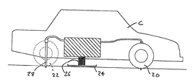
- FIG. 1 is a schematic sectional elevation of a model car incorporating a pick-up arrangement in accordance with the present invention
- FIG. 2 is a schematic plan view of the pick-up arrangement of the model car shown in FIG. 1;
- FIG. 3 is a view of a model terrain for the model car of FIGS. 1 and 2, and including an enlarged view of a portion of the running surface of the terrain;
- FIG. 4 is a side view to show the engagement of the pick-up arrangement of the model car with the running surface
- FIG. 5 is an isometric view showing the engagement of the pick-up probes of the model car with the contact pins of the running surface
- FIG. 6 is an isometric view showing the engagement of the pick-up plate of the model car with the contact pins of the running surface.
- FIG. 3 of the drawings there is shown a profiled terrain T for a model car to run over, the terrain T being formed from a sheet which comprises a base layer or substrate 10 having an array of contact pins 12 projecting upwardly from it.
- the substrate 10 is flexible so that it can be used to form a terrain of desired profile, forming a running surface for the model vehicle shown in FIGS. 1 and 2.
- Each of the contact pins 12 is of cylindrical shape and has a circumferential surface 14 forming a first electrode or contact: further, each contact pin 12 has a second electrode or contact 16 in the form of a disc-shaped central projection at its top.
- the two contacts 14 , 16 of each pin 12 are insulated from each other.
- the circumferential contacts 14 of all of the pins are connected together, for example on the upperside of the substrate 10
- the central contacts 16 of all of the pins are connected together, for example on the underside of the substrate 10 .
- a power supply is provided, with its opposite poles connected respectively to the two different electrodes of the contact pins.
- the model car C has front and rear pairs of wheels 20 , 22 and an electric motor (not shown) for driving at least one pair of these wheels. Also, the front pair of wheels are steerable. The car is arranged to be controlled remotely, to control its speed (both forward and reverse) and to control its steering.
- the model car further comprises a pick-up arrangement for drawing electrical power from the running surface.
- the pick-up arrangement comprises a pick-up plate 24 which is mounted horizontally by a coil spring 26 : the spring 26 urges the pick-up plate against the tops of the contact pins 12 of the running surface and accordingly into contact with the projecting central electrodes 16 .
- the edges of the pick-up plate 24 are curved or turned upwardly to prevent them catching on the pins 12 as the car moves over the running surface.
- the pick-up arrangement further comprises a set of four downwardly-projecting pins or probes 28 , positioned adjacent and inwardly of the respective wheels of the car.
- the probes 28 project down to below the bottom edges of the wheels and are preferably mounted on springs 29 (FIG. 4) which urge them downwardly and also give them resilient flexibility.
- the tops of the contact pins 12 of the substrate 10 form a running surface on which the wheels of the car rest, over which the car runs.
- the pick-up plate 24 slides over the tops of the contact pins 12 and mates with the central electrodes 16 of these (see also FIG. 6).
- the pick-up probes 28 project into the spaces between the contact pins 12 and move between the pins as the car moves over the running surface (see also FIG. 5).
- the pick-up probes 28 accordingly brush against the circumferential electrodes 14 of the contact pins: at any given instant in time, at least one of the pick-up probes 28 will be in contact with the electrode 14 of at least one contact pin, such that an electrical circuit is completed between the two poles of the power supply and the two terminals of the drive and control system of the model car.
Landscapes
- Toys (AREA)
Abstract
A model vehicle runs on a running surface which comprises a substrate having an array of contact pins, the tops of the contact pins forming one electrode and the sides of the contact pins forming a second electrode. The model vehicle comprises wheels for running over the running surface, an electrically powered drive means, a first pick-up for engaging the tops of the contact pins, and a second pick-up for engaging the sides of the contact pins.
Description
- The present invention relates to model vehicles and more particularly to electrically powered model vehicles.
- Generally, electrically powered model vehicles are either powered from batteries or from by means of a pick-up arrangement. In the case of battery-powered vehicles, the vehicle has a limited running life before the battery must be recharged or replaced. In the case of vehicles having a pickup arrangement, the vehicle generally runs on a track and is constrained to a predetermined path dictated by the coupling of the pick-up on the vehicle with conductor rails on the track.
- I have now devised a system in which a model vehicle draws its power via a pick-up arrangement but is not constrained to follow any predetermined path over its running surface.
- In accordance with the present invention, there is provided a running surface for a model vehicle, comprising a substrate having an array of contact pins projecting upwardly from it, the tops of the contact pins forming a first electrode and the side surfaces of the contact pins forming a second electrode.
- Also, in accordance with the present invention, there is provided a model vehicle which comprises wheels for engaging the above-defined running surface, electrically powered drive means for driving the wheels, and a pick-up arrangement which comprises a first pick-up for making contact with the tops of the contact pins of the above-defined running surface, and a second pick-up for making contact with the side surfaces of said contact pins.
- It will be appreciated that, in use, the two poles of an electrical power supply are connected to the respective electrodes of the running surface. An electric circuit is completed from the tops of the contact pins to the first pickup of the vehicle, then through the drive means of the vehicle to its second pick-up, and then to the sides of the contact pins.
- Preferably the first pick-up on the vehicle comprises a generally flat plate. Preferably the first pick-up is provided with means for urging it resiliently into contact with the tops of the contact pins of the running surface.
- Preferably the second pick-up of the vehicle comprises at least one elongate probe projecting downwardly to a level below the bottom edges of the wheels. Preferably there are four such probes, adjacent the respective wheels of the vehicle.
- Preferably the substrate of the running surface is flexible, so that the running surface may be formed into a terrain of desired profile.
- Preferably the contact pins of the running surface are cylindrical in form, the cylindrical circumferential surface of each pin forming its said second electrode. Preferably a projecting top portion of the contact pin forms its said first electrode.
- Preferably the model vehicle is provided with a remote control system for controlling its drive means. Preferably the remote control system also controls the steering of the vehicle.
- An embodiment of the present invention will now be described by way of example only and with reference to the accompanying drawings, in which:
- FIG. 1 is a schematic sectional elevation of a model car incorporating a pick-up arrangement in accordance with the present invention;
- FIG. 2 is a schematic plan view of the pick-up arrangement of the model car shown in FIG. 1;
- FIG. 3 is a view of a model terrain for the model car of FIGS. 1 and 2, and including an enlarged view of a portion of the running surface of the terrain;
- FIG. 4 is a side view to show the engagement of the pick-up arrangement of the model car with the running surface;
- FIG. 5 is an isometric view showing the engagement of the pick-up probes of the model car with the contact pins of the running surface; and
- FIG. 6 is an isometric view showing the engagement of the pick-up plate of the model car with the contact pins of the running surface.
- Referring firstly to FIG. 3 of the drawings, there is shown a profiled terrain T for a model car to run over, the terrain T being formed from a sheet which comprises a base layer or
substrate 10 having an array ofcontact pins 12 projecting upwardly from it. Thesubstrate 10 is flexible so that it can be used to form a terrain of desired profile, forming a running surface for the model vehicle shown in FIGS. 1 and 2. Each of thecontact pins 12 is of cylindrical shape and has acircumferential surface 14 forming a first electrode or contact: further, eachcontact pin 12 has a second electrode or contact 16 in the form of a disc-shaped central projection at its top. The twocontacts pin 12 are insulated from each other. Thecircumferential contacts 14 of all of the pins are connected together, for example on the upperside of thesubstrate 10, and thecentral contacts 16 of all of the pins are connected together, for example on the underside of thesubstrate 10. A power supply is provided, with its opposite poles connected respectively to the two different electrodes of the contact pins. - Referring to FIGS. 1 and 2 of the drawings, the model car C has front and rear pairs of
wheels - The model car further comprises a pick-up arrangement for drawing electrical power from the running surface. The pick-up arrangement comprises a pick-
up plate 24 which is mounted horizontally by a coil spring 26: thespring 26 urges the pick-up plate against the tops of thecontact pins 12 of the running surface and accordingly into contact with the projectingcentral electrodes 16. The edges of the pick-up plate 24 are curved or turned upwardly to prevent them catching on thepins 12 as the car moves over the running surface. The pick-up arrangement further comprises a set of four downwardly-projecting pins orprobes 28, positioned adjacent and inwardly of the respective wheels of the car. Theprobes 28 project down to below the bottom edges of the wheels and are preferably mounted on springs 29 (FIG. 4) which urge them downwardly and also give them resilient flexibility. - As shown in FIG. 4, the tops of the
contact pins 12 of thesubstrate 10 form a running surface on which the wheels of the car rest, over which the car runs. The pick-up plate 24 slides over the tops of thecontact pins 12 and mates with thecentral electrodes 16 of these (see also FIG. 6). The pick-up probes 28 project into the spaces between thecontact pins 12 and move between the pins as the car moves over the running surface (see also FIG. 5). The pick-up probes 28 accordingly brush against thecircumferential electrodes 14 of the contact pins: at any given instant in time, at least one of the pick-up probes 28 will be in contact with theelectrode 14 of at least one contact pin, such that an electrical circuit is completed between the two poles of the power supply and the two terminals of the drive and control system of the model car. - It will be appreciated that the system which has been described enables the model car to run over the running surface without being constrained to any predetermined path.
Claims (9)
1) A running surface for a model vehicle, comprising a substrate having an array of contact pins projecting upwardly from it, the tops of the contact pins forming a first electrode and the side surfaces of the contact pins forming a second electrode.
2) A running surface as claimed in claim 1 , in which said substrate is flexible.
3) A running surface as claimed in claim 1 , in which said contact pins are cylindrical in form, the cylindrical circumferential surface of each pin forming its said second electrode.
4) A running surface as claimed in claim 3 , in which a projecting top portion of each said pin forms its said first electrode.
5) A model vehicle for use on a running surface as claimed in any preceding claim, the vehicle comprising wheels for engaging said running surface, electrically powered drive means for driving said wheels, and a pick-up arrangement which comprises a first pick-up for making contact with the tops of said pins of said running surface, and a second pick-up for making contact with the side surfaces of said contact pins.
6) A model vehicle as claimed in claim 5 , in which said first pick-up comprises a generally flat plate.
7) A model vehicle as claimed in claim 5 , in which said first pick-up is provided with means for urging it resiliently into contact with the tops of said contact pins of said running surface.
8) A model vehicle as in claim 5 , in which said second pick-up comprises at least one elongate probe projecting downwardly to a level below the bottom edges of said wheels.
9) A model vehicle as claimed in claim 8 , in which said second pick-up comprises four said probes, adjacent respective said wheels.
Priority Applications (2)
| Application Number | Priority Date | Filing Date | Title |
|---|---|---|---|
| GB9927048A GB2356356B (en) | 1999-11-17 | 1999-11-17 | Model Vehicles |
| US10/121,312 US6644212B2 (en) | 1999-11-17 | 2002-04-12 | Model vehicles |
Applications Claiming Priority (2)
| Application Number | Priority Date | Filing Date | Title |
|---|---|---|---|
| GB9927048A GB2356356B (en) | 1999-11-17 | 1999-11-17 | Model Vehicles |
| US10/121,312 US6644212B2 (en) | 1999-11-17 | 2002-04-12 | Model vehicles |
Publications (2)
| Publication Number | Publication Date |
|---|---|
| US20030192451A1 true US20030192451A1 (en) | 2003-10-16 |
| US6644212B2 US6644212B2 (en) | 2003-11-11 |
Family
ID=30117176
Family Applications (1)
| Application Number | Title | Priority Date | Filing Date |
|---|---|---|---|
| US10/121,312 Expired - Fee Related US6644212B2 (en) | 1999-11-17 | 2002-04-12 | Model vehicles |
Country Status (2)
| Country | Link |
|---|---|
| US (1) | US6644212B2 (en) |
| GB (1) | GB2356356B (en) |
Families Citing this family (1)
| Publication number | Priority date | Publication date | Assignee | Title |
|---|---|---|---|---|
| US7172196B2 (en) * | 2002-12-10 | 2007-02-06 | Mitch Randall | Systems and methods for providing electric power to mobile and arbitrarily positioned devices |
Family Cites Families (8)
| Publication number | Priority date | Publication date | Assignee | Title |
|---|---|---|---|---|
| DE705352C (en) * | 1939-01-10 | 1941-04-25 | Karl Heinz Otten | Electric toy vehicle |
| DE803756C (en) * | 1948-10-02 | 1951-04-09 | Karl Fuchs | Electric vehicle toys |
| DE1515918A1 (en) * | 1951-01-28 | 1969-07-31 | Krichel Helmut | Plate for drawing electricity |
| DE968836C (en) * | 1951-12-05 | 1958-04-03 | Gerhard Schaudt Dr | Electric power supply device for consumers equipped with pantographs, especially for portable, electric toys |
| US2768697A (en) * | 1953-05-20 | 1956-10-30 | Shotwell Allen | Remotely controlled electrically propelled vehicle |
| US5868076A (en) * | 1996-02-28 | 1999-02-09 | Myus; David Allan | Slotless electric track for vehicles |
| US5782186A (en) | 1997-01-03 | 1998-07-21 | Futech Educational Products, Inc. | Model motor vehicle track system and method for making the same |
| DE10003557C2 (en) * | 2000-01-27 | 2001-12-06 | Sts Racing Gmbh | Toy vehicle with adjustable magnetic grip |
-
1999
- 1999-11-17 GB GB9927048A patent/GB2356356B/en not_active Expired - Fee Related
-
2002
- 2002-04-12 US US10/121,312 patent/US6644212B2/en not_active Expired - Fee Related
Also Published As
| Publication number | Publication date |
|---|---|
| GB2356356B (en) | 2003-10-22 |
| US6644212B2 (en) | 2003-11-11 |
| GB2356356A (en) | 2001-05-23 |
| GB9927048D0 (en) | 2000-01-12 |
Similar Documents
| Publication | Publication Date | Title |
|---|---|---|
| JP3463344B2 (en) | Rechargeable traveling toy, charging device for traveling toy, and traveling path for traveling toy | |
| US6762586B2 (en) | Rechargeable system for movable toy | |
| JPH05251068A (en) | Rechargeable power source | |
| CA1099924A (en) | Toy vehicle game having battery charging means | |
| JPH08838A (en) | Vehicle toy of electromagnetic induction charging system | |
| US6644212B2 (en) | Model vehicles | |
| JP2002158062A (en) | External power connecting device for mobile robot | |
| US6439951B1 (en) | Connecting apparatus and robot | |
| CN107040028B (en) | Charging device | |
| US5963002A (en) | Wireless electrical connection to mobile robots or vehicles | |
| JP2006034432A (en) | Self-propelled cleaner unit | |
| KR101175024B1 (en) | Power supply for electric bicycle | |
| CN114156989A (en) | Charging device and charging system for wheeled robot | |
| JP2001273945A (en) | External power supply connecting structure of mobile robot | |
| JP3985136B2 (en) | Charge / start / stop control device for running toys | |
| CN216720961U (en) | Charging device and charging system for wheeled robot | |
| JP3558417B2 (en) | Power supply device for moving objects | |
| JP2000190759A (en) | Power supply device for moving objects | |
| JPH11313987A (en) | Monorail type running toy | |
| JPH0511906Y2 (en) | ||
| JP4255445B2 (en) | Vehicle toy | |
| CN213831356U (en) | Portable wireless charging device of electric automobile | |
| EP0553555A2 (en) | Improvements in toy cars | |
| US20080258676A1 (en) | Toy vehicle capable of collecting solar power | |
| US3500580A (en) | Electric locomotive for toy and model railroads |
Legal Events
| Date | Code | Title | Description |
|---|---|---|---|
| REMI | Maintenance fee reminder mailed | ||
| FPAY | Fee payment |
Year of fee payment: 4 |
|
| SULP | Surcharge for late payment | ||
| FPAY | Fee payment |
Year of fee payment: 8 |
|
| REMI | Maintenance fee reminder mailed | ||
| LAPS | Lapse for failure to pay maintenance fees | ||
| STCH | Information on status: patent discontinuation |
Free format text: PATENT EXPIRED DUE TO NONPAYMENT OF MAINTENANCE FEES UNDER 37 CFR 1.362 |
|
| STCH | Information on status: patent discontinuation |
Free format text: PATENT EXPIRED DUE TO NONPAYMENT OF MAINTENANCE FEES UNDER 37 CFR 1.362 |
|
| FP | Lapsed due to failure to pay maintenance fee |
Effective date: 20151111 |