US20030192364A1 - Propellant test apparatus and method - Google Patents
Propellant test apparatus and method Download PDFInfo
- Publication number
- US20030192364A1 US20030192364A1 US10/120,830 US12083002A US2003192364A1 US 20030192364 A1 US20030192364 A1 US 20030192364A1 US 12083002 A US12083002 A US 12083002A US 2003192364 A1 US2003192364 A1 US 2003192364A1
- Authority
- US
- United States
- Prior art keywords
- exhaust channel
- propellant
- supplemental
- exhaust
- combustion chamber
- Prior art date
- Legal status (The legal status is an assumption and is not a legal conclusion. Google has not performed a legal analysis and makes no representation as to the accuracy of the status listed.)
- Granted
Links
- 239000003380 propellant Substances 0.000 title claims abstract description 44
- 238000012360 testing method Methods 0.000 title claims abstract description 40
- 238000000034 method Methods 0.000 title claims abstract description 8
- 230000000153 supplemental effect Effects 0.000 claims abstract description 36
- 238000002485 combustion reaction Methods 0.000 claims abstract description 24
- 239000007789 gas Substances 0.000 claims abstract description 20
- 239000004449 solid propellant Substances 0.000 claims abstract description 15
- 238000010998 test method Methods 0.000 claims 1
- 238000010276 construction Methods 0.000 description 7
- PXBRQCKWGAHEHS-UHFFFAOYSA-N dichlorodifluoromethane Chemical compound FC(F)(Cl)Cl PXBRQCKWGAHEHS-UHFFFAOYSA-N 0.000 description 4
- 235000019404 dichlorodifluoromethane Nutrition 0.000 description 4
- 238000004891 communication Methods 0.000 description 1
- 238000012986 modification Methods 0.000 description 1
- 230000004048 modification Effects 0.000 description 1
Images


Classifications
-
- G—PHYSICS
- G01—MEASURING; TESTING
- G01N—INVESTIGATING OR ANALYSING MATERIALS BY DETERMINING THEIR CHEMICAL OR PHYSICAL PROPERTIES
- G01N25/00—Investigating or analyzing materials by the use of thermal means
- G01N25/50—Investigating or analyzing materials by the use of thermal means by investigating flash-point; by investigating explosibility
-
- G—PHYSICS
- G01—MEASURING; TESTING
- G01N—INVESTIGATING OR ANALYSING MATERIALS BY DETERMINING THEIR CHEMICAL OR PHYSICAL PROPERTIES
- G01N33/00—Investigating or analysing materials by specific methods not covered by groups G01N1/00 - G01N31/00
- G01N33/22—Fuels; Explosives
- G01N33/222—Solid fuels, e.g. coal
Definitions
- the present invention relates to apparatus and method for testing solid propellants and, more particularly, to a new and improved apparatus and method for testing solid propellants over a wide pressure range that is independent of the burning surface area of the propellant.
- the new and improved propellant test apparatus and method of the present invention provides a supplemental exhaust channel for the gases of the burning propellant being tested in addition to the normal or primary exhaust channel and exit nozzle at the end of the exhaust housing for the test apparatus.
- the flow of propellant gases through the supplemental exhaust channel is controlled by a valve of any suitable construction which can be controlled to vary the size of the supplemental exhaust channel over a wide range from fully open to fully closed.
- the size of the supplemental exhaust channel By varying the size of the supplemental exhaust channel, the flow of exhaust gases through the exit nozzle and the supplemental exhaust channel can be varied to control the combustion chamber pressure on the solid propellant being tested over a wide range that is independent of the burning surface area of the propellant. Accordingly, it is possible with the propellant test apparatus of the present invention to test the burning characteristics of different types of propellants over a wide pressure range that can be easily selectively controlled.
- FIG. 1 is a side elevational view in section of a propellant test apparatus that is known in the prior art
- FIG. 2 is a side elevational view in section of a first embodiment of the new and improved propellant test apparatus of the present invention
- FIG. 3 is a side elevational view in section of a second embodiment of the propellant test apparatus of the present invention.
- FIG. 4 is an enlarged plan view of one embodiment of a valve for the supplemental exhaust channel taken substantially along line 4 - 4 in FIG. 2, showing the valve in a fully closed position;
- FIG. 5 is a sectional view similar to that in FIG. 4, showing the valve for the supplemental exhaust channel in a fully open position;
- FIG. 6 is an enlarged elevational view in section of a second embodiment of a valve construction for the supplemental exhaust channel, showing the valve member in a fully closed position;
- FIG. 7 is a sectional view similar to that of FIG. 6, showing the valve member in a fully open position.
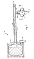
- FIG. 1 illustrates a test apparatus 10 for a solid propellant 12 of the type that is currently used and known in the prior art.
- the test apparatus 10 comprises a combustion chamber 14 in which the propellant 12 is mounted, an igniter 16 of any suitable type extending into the combustion chamber 14 for igniting the propellant 12 , an exhaust channel 18 in an exhaust housing 20 extending from the combustion chamber 12 to an exit nozzle 22 of any suitable construction.
- the propellant In order to test the burning characteristics of the solid propellant 12 under different pressures, the propellant is formed of a stepped construction such that the burning surface area will be reduced to lower the combustion chamber pressure as the propellant burns into smaller stepped surface areas. It will be readily seen, therefore, that this prior art test apparatus can only test the burning characteristics of the propellant over a limited pressure range determined by the size of the burning surface areas of the propellant.
- FIG. 2 illustrates a first embodiment of the new and improved propellant test apparatus 110 of the present invention which comprises a combustion chamber 114 in which a solid propellant 112 of any suitable or desired type is mounted in any suitable manner, and an igniter 116 of any suitable type extending into the combustion chamber 114 for igniting the propellant 112 .
- a primary exhaust channel 118 extends through an exhaust housing 120 from the combustion chamber 114 to an exit nozzle 122 of any suitable construction.
- a supplemental exhaust channel 124 extends from the primary exhaust channel 118 through an exhaust valve 126 of any suitable construction to a supplemental exhaust opening 128 .
- the exhaust channel 124 is formed in a housing 130 connected at one end to the exhaust housing 120 and at the other end to the exhaust valve 126 .
- the valve 126 is constructed to be selectively movable to control the size of the supplemental exhaust channel 124 and thus the amount of flow of the exhaust gases from the burning propellant 112 through the supplemental exhaust opening 128 .
- the combustion chamber pressure on the burning propellant 112 can be varied over a wide range to enable the burning characteristics of the propellant 112 to be tested at many different pressures that are independent of the burning surface area of the propellant. Accordingly, the new and improved propellant test apparatus 110 is a significant improvement over the prior art apparatus shown in FIG. 1.
- FIGS. 4 and 5 illustrate one embodiment of an exhaust valve 126 for controlling the size of the supplemental exhaust channel 124 shown in FIG. 2.
- the exhaust valve 126 comprises a pair of opposed pistons or valve members 132 that are slideably mounted in housings 134 for movement between the positions shown in FIG. 4 wherein they close the supplemental exhaust channel 124 and the positions shown in FIG. 5 wherein they are disposed outside of the supplemental exhaust channel 124 such that it is fully open.
- the movement of the pistons 132 may be controlled in any suitable or well known manner.
- FIGS. 6 and 7 illustrate a second embodiment of an exhaust valve 326 for controlling the size of the supplemental exhaust channel 124 shown in FIG. 2.
- the valve 326 comprises a piston or valve member 332 that is slidably mounted in a housing 334 for movement between the position in FIG. 6 wherein it closes the supplemental exhaust channel 124 and the position shown in FIG. 7 wherein it is disposed outside of the supplemental exhaust channel 124 such that it is fully open to enable flow through the lateral exhaust openings 124 a.
- the first embodiment of the exhaust valve 126 shown in FIGS. 4 and 5 may comprise lateral exhaust openings like the exhaust openings 124 a in the second embodiment shown in FIGS. 6 and 7.
- FIG. 3 illustrates a second embodiment of the propellant test apparatus 210 of the present invention that is very similar in construction and operation to the first embodiment shown in FIG. 2.
- the test apparatus 210 of the second embodiment comprises a combustion chamber 214 for containing a test propellant 212 , an igniter 216 extending into the combustion chamber 214 , a primary exhaust channel 218 in an exhaust housing 220 extending from the combustion chamber 214 to an exit nozzle 222 , and a supplemental exhaust channel 224 in a housing 230 that is connected to an exhaust valve 226 for controlling the flow of exhaust gases from the supplemental exhaust channel 224 to the supplemental exhaust opening 228 .
- the second embodiment of the propellant test apparatus 210 further comprises an auxiliary exhaust channel 240 disposed in an auxiliary housing 242 connected to the exhaust housing 220 .
- the inner end of the auxiliary exhaust channel 240 is in communication with the primary exhaust channel 218 , and the outer end of the auxiliary exhaust channel 240 is closed by a burst disk 244 of any suitable type that is constructed to fail at a predetermined pressure.
- the auxiliary exhaust channel 240 and burst disk 244 serve as a safety device to vent exhaust gases from the primary exhaust channel 218 in the event the exhaust gas pressure exceeds the predetermined pressure at which the burst disk 244 will fail. In this manner, a potentially dangerous build-up of propellant exhaust gas pressure in the exhaust housing 220 is effectively prevented.
- the new and improved solid propellant test apparatus and method of the present invention provide a simple and effective means of testing the burning characteristics of a solid propellant over a wide combustion pressure range that is independent of the burning surface area of the propellant.
Landscapes
- Chemical & Material Sciences (AREA)
- Health & Medical Sciences (AREA)
- Life Sciences & Earth Sciences (AREA)
- General Health & Medical Sciences (AREA)
- Analytical Chemistry (AREA)
- Biochemistry (AREA)
- Physics & Mathematics (AREA)
- General Physics & Mathematics (AREA)
- Immunology (AREA)
- Pathology (AREA)
- Engineering & Computer Science (AREA)
- Food Science & Technology (AREA)
- Medicinal Chemistry (AREA)
- Testing Of Engines (AREA)
- Investigating Or Analyzing Materials Using Thermal Means (AREA)
Abstract
Description
- The present invention relates to apparatus and method for testing solid propellants and, more particularly, to a new and improved apparatus and method for testing solid propellants over a wide pressure range that is independent of the burning surface area of the propellant.
- In previously used solid propellant test apparatus, the burning characteristics of the propellant have been tested under different pressures by varying the burning surface area of the propellant. While such test apparatus has performed satisfactorily, it has not been completely satisfactory in that it has only been possible to test the burning characteristics of the propellant over a limited number of pressures determined by the different burning surface areas of the propellant. A need has arisen, therefore, for a new and improved propellant test apparatus that is capable of testing solid propellants of different types over a wide pressure range independent of the burning surface area of the propellants. The test apparatus of the present invention fills this need.
- The new and improved propellant test apparatus and method of the present invention provides a supplemental exhaust channel for the gases of the burning propellant being tested in addition to the normal or primary exhaust channel and exit nozzle at the end of the exhaust housing for the test apparatus. The flow of propellant gases through the supplemental exhaust channel is controlled by a valve of any suitable construction which can be controlled to vary the size of the supplemental exhaust channel over a wide range from fully open to fully closed. By varying the size of the supplemental exhaust channel, the flow of exhaust gases through the exit nozzle and the supplemental exhaust channel can be varied to control the combustion chamber pressure on the solid propellant being tested over a wide range that is independent of the burning surface area of the propellant. Accordingly, it is possible with the propellant test apparatus of the present invention to test the burning characteristics of different types of propellants over a wide pressure range that can be easily selectively controlled.
- FIG. 1 is a side elevational view in section of a propellant test apparatus that is known in the prior art;
- FIG. 2 is a side elevational view in section of a first embodiment of the new and improved propellant test apparatus of the present invention;
- FIG. 3 is a side elevational view in section of a second embodiment of the propellant test apparatus of the present invention;
- FIG. 4 is an enlarged plan view of one embodiment of a valve for the supplemental exhaust channel taken substantially along line 4-4 in FIG. 2, showing the valve in a fully closed position;
- FIG. 5 is a sectional view similar to that in FIG. 4, showing the valve for the supplemental exhaust channel in a fully open position;
- FIG. 6 is an enlarged elevational view in section of a second embodiment of a valve construction for the supplemental exhaust channel, showing the valve member in a fully closed position; and
- FIG. 7 is a sectional view similar to that of FIG. 6, showing the valve member in a fully open position.
- FIG. 1 illustrates a
test apparatus 10 for asolid propellant 12 of the type that is currently used and known in the prior art. Thetest apparatus 10 comprises acombustion chamber 14 in which thepropellant 12 is mounted, anigniter 16 of any suitable type extending into thecombustion chamber 14 for igniting thepropellant 12, anexhaust channel 18 in anexhaust housing 20 extending from thecombustion chamber 12 to anexit nozzle 22 of any suitable construction. - In order to test the burning characteristics of the
solid propellant 12 under different pressures, the propellant is formed of a stepped construction such that the burning surface area will be reduced to lower the combustion chamber pressure as the propellant burns into smaller stepped surface areas. It will be readily seen, therefore, that this prior art test apparatus can only test the burning characteristics of the propellant over a limited pressure range determined by the size of the burning surface areas of the propellant. - FIG. 2 illustrates a first embodiment of the new and improved
propellant test apparatus 110 of the present invention which comprises acombustion chamber 114 in which asolid propellant 112 of any suitable or desired type is mounted in any suitable manner, and anigniter 116 of any suitable type extending into thecombustion chamber 114 for igniting thepropellant 112. Aprimary exhaust channel 118 extends through anexhaust housing 120 from thecombustion chamber 114 to anexit nozzle 122 of any suitable construction. - A
supplemental exhaust channel 124 extends from theprimary exhaust channel 118 through anexhaust valve 126 of any suitable construction to asupplemental exhaust opening 128. Theexhaust channel 124 is formed in ahousing 130 connected at one end to theexhaust housing 120 and at the other end to theexhaust valve 126. Thevalve 126 is constructed to be selectively movable to control the size of thesupplemental exhaust channel 124 and thus the amount of flow of the exhaust gases from theburning propellant 112 through thesupplemental exhaust opening 128. By controlling the flow of exhaust gases from the burningpropellant 112 through thesupplemental exhaust opening 128 in addition to the normal flow through theexit nozzle 122, the combustion chamber pressure on the burningpropellant 112 can be varied over a wide range to enable the burning characteristics of thepropellant 112 to be tested at many different pressures that are independent of the burning surface area of the propellant. Accordingly, the new and improvedpropellant test apparatus 110 is a significant improvement over the prior art apparatus shown in FIG. 1. - FIGS. 4 and 5 illustrate one embodiment of an
exhaust valve 126 for controlling the size of thesupplemental exhaust channel 124 shown in FIG. 2. Theexhaust valve 126 comprises a pair of opposed pistons orvalve members 132 that are slideably mounted inhousings 134 for movement between the positions shown in FIG. 4 wherein they close thesupplemental exhaust channel 124 and the positions shown in FIG. 5 wherein they are disposed outside of thesupplemental exhaust channel 124 such that it is fully open. The movement of thepistons 132 may be controlled in any suitable or well known manner. - FIGS. 6 and 7 illustrate a second embodiment of an
exhaust valve 326 for controlling the size of thesupplemental exhaust channel 124 shown in FIG. 2. Thevalve 326 comprises a piston orvalve member 332 that is slidably mounted in ahousing 334 for movement between the position in FIG. 6 wherein it closes thesupplemental exhaust channel 124 and the position shown in FIG. 7 wherein it is disposed outside of thesupplemental exhaust channel 124 such that it is fully open to enable flow through thelateral exhaust openings 124 a. - The first embodiment of the
exhaust valve 126 shown in FIGS. 4 and 5 may comprise lateral exhaust openings like theexhaust openings 124 a in the second embodiment shown in FIGS. 6 and 7. FIG. 3 illustrates a second embodiment of thepropellant test apparatus 210 of the present invention that is very similar in construction and operation to the first embodiment shown in FIG. 2. Thetest apparatus 210 of the second embodiment comprises acombustion chamber 214 for containing atest propellant 212, anigniter 216 extending into thecombustion chamber 214, aprimary exhaust channel 218 in anexhaust housing 220 extending from thecombustion chamber 214 to anexit nozzle 222, and asupplemental exhaust channel 224 in ahousing 230 that is connected to anexhaust valve 226 for controlling the flow of exhaust gases from thesupplemental exhaust channel 224 to thesupplemental exhaust opening 228. - The second embodiment of the
propellant test apparatus 210 further comprises anauxiliary exhaust channel 240 disposed in anauxiliary housing 242 connected to theexhaust housing 220. The inner end of theauxiliary exhaust channel 240 is in communication with theprimary exhaust channel 218, and the outer end of theauxiliary exhaust channel 240 is closed by aburst disk 244 of any suitable type that is constructed to fail at a predetermined pressure. Theauxiliary exhaust channel 240 andburst disk 244 serve as a safety device to vent exhaust gases from theprimary exhaust channel 218 in the event the exhaust gas pressure exceeds the predetermined pressure at which theburst disk 244 will fail. In this manner, a potentially dangerous build-up of propellant exhaust gas pressure in theexhaust housing 220 is effectively prevented. - Based on the foregoing description, it will be readily seen that the new and improved solid propellant test apparatus and method of the present invention provide a simple and effective means of testing the burning characteristics of a solid propellant over a wide combustion pressure range that is independent of the burning surface area of the propellant.
- While the invention has been described in connection with what is presently considered to be the most practical and preferred embodiment, it is to be understood that the invention is not to be limited to the disclosed embodiment, but on the contrary, is intended to cover various modifications and equivalent arrangements included within the spirit and scope of the appended claims.
Claims (10)
Priority Applications (3)
| Application Number | Priority Date | Filing Date | Title |
|---|---|---|---|
| US10/120,830 US6662629B2 (en) | 2002-04-12 | 2002-04-12 | Propellant test apparatus and method |
| PCT/US2003/010931 WO2003087565A2 (en) | 2002-04-12 | 2003-04-10 | Propellant test apparatus and method |
| AU2003223531A AU2003223531A1 (en) | 2002-04-12 | 2003-04-10 | Propellant test apparatus and method |
Applications Claiming Priority (1)
| Application Number | Priority Date | Filing Date | Title |
|---|---|---|---|
| US10/120,830 US6662629B2 (en) | 2002-04-12 | 2002-04-12 | Propellant test apparatus and method |
Publications (2)
| Publication Number | Publication Date |
|---|---|
| US20030192364A1 true US20030192364A1 (en) | 2003-10-16 |
| US6662629B2 US6662629B2 (en) | 2003-12-16 |
Family
ID=28790180
Family Applications (1)
| Application Number | Title | Priority Date | Filing Date |
|---|---|---|---|
| US10/120,830 Expired - Fee Related US6662629B2 (en) | 2002-04-12 | 2002-04-12 | Propellant test apparatus and method |
Country Status (3)
| Country | Link |
|---|---|
| US (1) | US6662629B2 (en) |
| AU (1) | AU2003223531A1 (en) |
| WO (1) | WO2003087565A2 (en) |
Cited By (10)
| Publication number | Priority date | Publication date | Assignee | Title |
|---|---|---|---|---|
| CN100523807C (en) * | 2005-06-03 | 2009-08-05 | 中国科学院力学研究所 | Device for testing deflagrability of condensed fire detonator under condition of high termerature and high pressure |
| CN102279250A (en) * | 2011-04-02 | 2011-12-14 | 中国人民解放军国防科学技术大学 | Method for measuring burning velocity of solid propellant |
| CN102426215A (en) * | 2011-09-15 | 2012-04-25 | 西北工业大学 | A solid propellant crack growth test device |
| CN102967526A (en) * | 2012-11-28 | 2013-03-13 | 西北工业大学 | Method for measuring relationship between actual temperature and pressure in combustion process through constant volume combustor method |
| CN102980970A (en) * | 2012-11-28 | 2013-03-20 | 西北工业大学 | Method for obtaining propelling agent combustion speed by utilizing constant-capacity combustor |
| CN103604905A (en) * | 2013-11-20 | 2014-02-26 | 西安近代化学研究所 | Combustion speed testing method for gel propellant |
| CN105021766A (en) * | 2015-08-03 | 2015-11-04 | 南京理工大学 | High-pressure-resisting combustion chamber with laser lens and observation window which are convenient to wipe |
| CN106198849A (en) * | 2016-09-14 | 2016-12-07 | 中国科学技术大学 | A kind of test device for solid propellant combustion rate/combustion temperature and method of testing thereof |
| CN106482790A (en) * | 2016-11-09 | 2017-03-08 | 四川航天机电工程研究所 | Solid rocket propellant combustion measurement device and measuring method based on Fire Radiation |
| CN114563176A (en) * | 2022-04-27 | 2022-05-31 | 西安航天动力研究所 | Bolt injector and needle valve dynamic characteristic testing device and method thereof |
Families Citing this family (2)
| Publication number | Priority date | Publication date | Assignee | Title |
|---|---|---|---|---|
| US8122757B2 (en) * | 2009-03-20 | 2012-02-28 | New Mexico Technical Research Foundation | Propellant ignition testing apparatus having a compressively sealable chamber |
| RU2403430C1 (en) * | 2009-06-30 | 2010-11-10 | Государственное унитарное предприятие "Конструкторское бюро приборостроения" | Method for benchmark testing of power units comprising pyrotechnical and/or powder compositions, and device for its realisation |
Family Cites Families (11)
| Publication number | Priority date | Publication date | Assignee | Title |
|---|---|---|---|---|
| US3165924A (en) | 1963-07-18 | 1965-01-19 | Wolff Harry | Nozzle material firing evaluation means and system |
| US3267721A (en) | 1963-11-15 | 1966-08-23 | Kenneth H Jacobs | Apparatus for determining the burning rates of solid rocket propellants |
| US3580049A (en) | 1968-07-25 | 1971-05-25 | Us Navy | Rocket burn rate testing device |
| US3701278A (en) | 1970-02-17 | 1972-10-31 | Thiokol Chemical Corp | Test apparatus for combustion evaluation |
| DE3021778C2 (en) | 1980-06-10 | 1982-11-18 | Kistler Instrumente Ag, Winterthur | Force transducers, in particular for ballistic pressure measurements |
| US4349200A (en) | 1980-07-28 | 1982-09-14 | The Secretary Of State For Defence In Her Britannic Majesty's Government Of The United Kingdom Of Great Britain And Northern Ireland | Gas gun for ballistic testing |
| US4523475A (en) | 1983-09-19 | 1985-06-18 | The United States Of America As Represented By The Secretary Of The Air Force | Simultaneous incremental strain/incremental temperature analog device for, and method, of testing for stress response |
| US4554823A (en) | 1984-06-25 | 1985-11-26 | The United States Of America As Represented By The Secretary Of The Army | Method for burning rate characterization of solid propellants |
| US4759215A (en) | 1986-04-18 | 1988-07-26 | Morton Thiokol, Inc. | High strain capability ballistic test device for solid propellant rocket motors |
| US5052817A (en) | 1989-11-30 | 1991-10-01 | The United States Of America As Represented By The Administrator Of The National Aeronautics And Space Administration | Ignitability test method and apparatus |
| US5419119A (en) | 1993-07-29 | 1995-05-30 | The United States Of America As Represented By The Secretary Of The Navy | High pressure slab motor |
-
2002
- 2002-04-12 US US10/120,830 patent/US6662629B2/en not_active Expired - Fee Related
-
2003
- 2003-04-10 AU AU2003223531A patent/AU2003223531A1/en not_active Abandoned
- 2003-04-10 WO PCT/US2003/010931 patent/WO2003087565A2/en not_active Ceased
Cited By (10)
| Publication number | Priority date | Publication date | Assignee | Title |
|---|---|---|---|---|
| CN100523807C (en) * | 2005-06-03 | 2009-08-05 | 中国科学院力学研究所 | Device for testing deflagrability of condensed fire detonator under condition of high termerature and high pressure |
| CN102279250A (en) * | 2011-04-02 | 2011-12-14 | 中国人民解放军国防科学技术大学 | Method for measuring burning velocity of solid propellant |
| CN102426215A (en) * | 2011-09-15 | 2012-04-25 | 西北工业大学 | A solid propellant crack growth test device |
| CN102967526A (en) * | 2012-11-28 | 2013-03-13 | 西北工业大学 | Method for measuring relationship between actual temperature and pressure in combustion process through constant volume combustor method |
| CN102980970A (en) * | 2012-11-28 | 2013-03-20 | 西北工业大学 | Method for obtaining propelling agent combustion speed by utilizing constant-capacity combustor |
| CN103604905A (en) * | 2013-11-20 | 2014-02-26 | 西安近代化学研究所 | Combustion speed testing method for gel propellant |
| CN105021766A (en) * | 2015-08-03 | 2015-11-04 | 南京理工大学 | High-pressure-resisting combustion chamber with laser lens and observation window which are convenient to wipe |
| CN106198849A (en) * | 2016-09-14 | 2016-12-07 | 中国科学技术大学 | A kind of test device for solid propellant combustion rate/combustion temperature and method of testing thereof |
| CN106482790A (en) * | 2016-11-09 | 2017-03-08 | 四川航天机电工程研究所 | Solid rocket propellant combustion measurement device and measuring method based on Fire Radiation |
| CN114563176A (en) * | 2022-04-27 | 2022-05-31 | 西安航天动力研究所 | Bolt injector and needle valve dynamic characteristic testing device and method thereof |
Also Published As
| Publication number | Publication date |
|---|---|
| AU2003223531A8 (en) | 2003-10-27 |
| WO2003087565A3 (en) | 2004-02-05 |
| WO2003087565A2 (en) | 2003-10-23 |
| AU2003223531A1 (en) | 2003-10-27 |
| US6662629B2 (en) | 2003-12-16 |
Similar Documents
| Publication | Publication Date | Title |
|---|---|---|
| US6662629B2 (en) | Propellant test apparatus and method | |
| US5609359A (en) | Pintle controlled orifice inflator | |
| US7143775B2 (en) | Valve element | |
| AU703663B2 (en) | Safety relief valve assembly for a fluid displacement apparatus | |
| US4188972A (en) | Gas valve assembly | |
| US7347449B2 (en) | Inflator having a variable gas flow throttle | |
| US5711340A (en) | Gas pressure reducing regulator | |
| CA2203842A1 (en) | Instant-on vented tank valve with manual override and method of operation thereof | |
| US5618057A (en) | Continuously variable controlled orifice inflator | |
| WO2004067297A3 (en) | Adaptive output, toroidal-shaped pyrotechnic inflator | |
| WO2006088367A3 (en) | A valve for providing a gas pulse | |
| JP2003521658A (en) | Excess pressure release device for gas | |
| EP2817603B1 (en) | Method of testing a gas shut-down valve and a system for exercising the method | |
| CN1620326B (en) | valve parts | |
| US5186198A (en) | Intake manifold relief valve | |
| US6062258A (en) | Gas pressure regulator having burn-out protection system | |
| US6073665A (en) | Charging method and charging structure of combustible gas and oxidizer gas, and material to be charged by using the charging method and the charging structure | |
| JPH10339383A (en) | Rapid speed opening pressure governing valve | |
| US4375873A (en) | Temperature responsive valve | |
| EP2054589B1 (en) | Pressure control valve, crankcase ventilating device and method for operating the latter | |
| EP0109790A2 (en) | Apparatus for controlling the outflow of gas from a propellant augmented, pressurized gas dispensing device | |
| KR101491837B1 (en) | A time delay valve for operating fire extinguishing valve in ship | |
| WO2025186358A8 (en) | Gas generator | |
| KR20130070513A (en) | A device for sound damping gas exiting from a pressure container, and a submarine with the device | |
| JP2704386B2 (en) | Closing valve mechanism |
Legal Events
| Date | Code | Title | Description |
|---|---|---|---|
| AS | Assignment |
Owner name: ATLANTIC RESEARCH CORPORATION, VIRGINIA Free format text: ASSIGNMENT OF ASSIGNORS INTEREST;ASSIGNORS:KHADDURI, FARID M.;SPEAR, GUY BRUCE;REEL/FRAME:013020/0087 Effective date: 20020531 |
|
| AS | Assignment |
Owner name: AEROJET-GENERAL CORPORATION, CALIFORNIA Free format text: ASSIGNMENT OF ASSIGNORS INTEREST;ASSIGNOR:ATLANTIC RESEARCH CORPORATION;REEL/FRAME:014699/0111 Effective date: 20031017 |
|
| AS | Assignment |
Owner name: WACHOVIA BANK, NATIONAL ASSOCIATION, AS ADMINISTRA Free format text: NOTICE OF GRANT OF SECURITY INTEREST;ASSIGNOR:AEROJET-GENERAL CORPORATION;REEL/FRAME:015766/0560 Effective date: 20041206 |
|
| FEPP | Fee payment procedure |
Free format text: PAYOR NUMBER ASSIGNED (ORIGINAL EVENT CODE: ASPN); ENTITY STATUS OF PATENT OWNER: LARGE ENTITY |
|
| FPAY | Fee payment |
Year of fee payment: 4 |
|
| REMI | Maintenance fee reminder mailed | ||
| LAPS | Lapse for failure to pay maintenance fees | ||
| STCH | Information on status: patent discontinuation |
Free format text: PATENT EXPIRED DUE TO NONPAYMENT OF MAINTENANCE FEES UNDER 37 CFR 1.362 |
|
| FP | Lapsed due to failure to pay maintenance fee |
Effective date: 20111216 |