US20030192220A1 - Structure of a side rail of an advertising panel - Google Patents
Structure of a side rail of an advertising panel Download PDFInfo
- Publication number
- US20030192220A1 US20030192220A1 US10/122,200 US12220002A US2003192220A1 US 20030192220 A1 US20030192220 A1 US 20030192220A1 US 12220002 A US12220002 A US 12220002A US 2003192220 A1 US2003192220 A1 US 2003192220A1
- Authority
- US
- United States
- Prior art keywords
- advertising panel
- side rail
- corner
- advertising
- board
- Prior art date
- Legal status (The legal status is an assumption and is not a legal conclusion. Google has not performed a legal analysis and makes no representation as to the accuracy of the status listed.)
- Abandoned
Links
- NJPPVKZQTLUDBO-UHFFFAOYSA-N novaluron Chemical compound C1=C(Cl)C(OC(F)(F)C(OC(F)(F)F)F)=CC=C1NC(=O)NC(=O)C1=C(F)C=CC=C1F NJPPVKZQTLUDBO-UHFFFAOYSA-N 0.000 claims abstract description 25
- 230000000694 effects Effects 0.000 description 1
Images


Classifications
-
- G—PHYSICS
- G09—EDUCATION; CRYPTOGRAPHY; DISPLAY; ADVERTISING; SEALS
- G09F—DISPLAYING; ADVERTISING; SIGNS; LABELS OR NAME-PLATES; SEALS
- G09F15/00—Boards, hoardings, pillars, or like structures for notices, placards, posters, or the like
- G09F15/0006—Boards, hoardings, pillars, or like structures for notices, placards, posters, or the like planar structures comprising one or more panels
- G09F15/0012—Boards, hoardings, pillars, or like structures for notices, placards, posters, or the like planar structures comprising one or more panels frames therefor
-
- A—HUMAN NECESSITIES
- A47—FURNITURE; DOMESTIC ARTICLES OR APPLIANCES; COFFEE MILLS; SPICE MILLS; SUCTION CLEANERS IN GENERAL
- A47G—HOUSEHOLD OR TABLE EQUIPMENT
- A47G1/00—Mirrors; Picture frames or the like, e.g. provided with heating, lighting or ventilating means
- A47G1/06—Picture frames
- A47G1/0605—Picture frames made from extruded or moulded profiles, e.g. of plastic or metal
- A47G1/0611—Picture frames made from extruded or moulded profiles, e.g. of plastic or metal the profiles having clamping action; Elongated clips
-
- G—PHYSICS
- G09—EDUCATION; CRYPTOGRAPHY; DISPLAY; ADVERTISING; SEALS
- G09F—DISPLAYING; ADVERTISING; SIGNS; LABELS OR NAME-PLATES; SEALS
- G09F1/00—Cardboard or like show-cards of foldable or flexible material
- G09F1/10—Supports or holders for show-cards
- G09F1/12—Frames therefor
Definitions
- the present invention relates to a design of a corner pedestal for an advertising panel, and more particularly to a design of a corner pedestal that enables a fast changing of simply with easy open and close side rails of an advertising panel.
- the traders In the rapidly developed industrial and commercial society, the traders have to decorate their product or put an advertisement in an advertising medium in order to sell their product smoothly. Although there are many kinds of advertising media, the best way to catch people's attention in t he darkness is the advertising panel.
- the structure of advertising panel and its translucent board used to be very heavy. Now they have improved to be a light and thin structure.
- the translucent board of the advertising panel in various models are to some extent made light.
- the traders have to change a new advertisement in time for receiving of full attention. Therefore, the advertisement board of the advertising panel should be easy to change and be pleasing to the eye.
- the advertising panel is popular because of changeability. However, the conventional structure of the advertising panel has a lot of trouble to change its advertisement board.
- Taiwan Patent Publication No.356275 discloses a conventional structure of an advertising panel.
- FIG. 3 is sectional view illustrating the conventional structure of the advertising panel.
- FIG. 4 is a partial enlarges view illustrating the conventional structure of the advertising panel.
- the advertising panel includes a framework 10 arranged a plate at both the front and rear end of the framework 10 , and a light-guided board of a luminous body is installed between the front plate and the rear plate.
- the framework 10 is composed of several side rails 101 and a corner pedestal 102 .
- the side rails 101 are further composed of a front side rail 1011 and a rear side rail 1012 .
- a slot plate 10111 is formed on one side of the front side rail 1011 .
- Several through holes 10112 are arranged in the slot plate 10111 .
- a groove 10113 is formed on another side of the front side rail 1011 .
- a front end of the groove 10113 is extending to the plate surface.
- a batten 103 having an inserted portion is tightly inserted into the groove 10113 .
- An internal plate 10121 is formed on one side of the rear side rail 1012 .
- a row of groove 10122 is fully arranged in the internal plate 10121 .
- a fixed groove 10123 is formed on a flange of the internal plate 10121 .
- the front side rail 1011 is connected with the rear side rail 1012 and the slot plate 10111 is inserted into the fixed groove 10123 of the rear side rail 1012 .
- the groove 10122 of the rear side rail 1012 is screwed to lock into the through hole 10112 of the front side rail 1011 by using a screw 104 .
- a joint flange portion 10124 is formed in the inner side of the internal plate 10121 of the rear side rail 1012 .
- a connecting pipe 1021 is formed at both side of a right angle framework 102 .
- a positional groove 1022 formed in the connecting pipe 1021 is then tightly inserted into the joint flange portion 10124 .
- FIGS. 5 and 6 illustrating another embodiment of the conventional advertising side rail.
- the advertising panel includes a framework 20 which can be lifted.
- a deforming elastic segment not shown, is installed between a side rail 20 and a cover plate 201 to control the opening and closing of the cover plate 201 .
- the two end portions of the cover plate 201 is assumed a dip angle to connect with each other, the dip angle of the end portions will get stuck and against each other when the cover plate is opened for changing the advertising board. Therefore, the angle of opening the cover plate 201 will be reduced substantially and it will be inconvenient for workers to exchange and draw out the advertising board.
- the conventional advertising panel does not solve the problem of changing an advertising board conveniently. It is therefore desirable to develop a design of a corner pedestal for an advertising panel which is capable of opening and closing its side rail easily.
- a primary object of the present invention is to provide an improved structure of a corner pedestal that enables a fast changing of simply with an easy open and close side rail of an advertising panel.
- an advertising panel of the present invention mainly includes a framework having four liftable side rails and four corner pedestals. These side rails can be lifted easily and be connected to these corner pedestals.
- the corner pedestal is hollow in its internal part and the L-shaped side of the corner pedestal is an opening which is used for connecting to these corner pedestals.
- FIG. 1 shows a corner pedestal of an advertising panel in an assembled state.
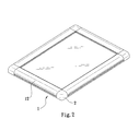
- FIG. 2 shows a preferred embodiment of the present invention.
- FIG. 3 is a sectional view of a conventional advertising panel.
- FIG. 4 is a partially enlarged view of a conventional advertising panel.
- FIG. 5 shows another embodiment of a conventional advertising panel.
- FIG. 6 shows still another embodiment of a conventional advertising panel.
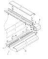
- FIG. 1 and FIG. 2 shows a corner pedestal of an advertising panel in an assembled state and a preferred embodiment of the present invention respectively.
- an advertising panel includes a framework having four side rails 1 and four corner pedestals 2 , which is use for connecting to the corner pedestal 2 .
- the side rail 1 is connected to a cover plate 12 from an outer side of a U-shaped base 11 .
- a deforming elastic segment 13 is installed between the base 11 and the cover plate 12 to control for opening and closing the cover plate 12 .
- the two inner side of the side rail respectively extending to lean against the plate surface may be used to clip various required board from both sides.
- Two lock holes 121 are provided on the two side of the base 11 .
- the corner pedestal 2 like a rectangular figure is hollow in its internal part and the L-shaped side of the corner pedestal is an opening 21 .
- a lock plate 22 is formed from the two adjacent ends of the extending of the opening 21 .
- a lock hole 221 is provided on the lock plate 22 corresponding to the lock hole 121 of the base 11 and a screw 3 is locked the side rail 1 and the corner pedestal 2 to connect the end of the two side rails 1 .
- a block slice 23 correspondingly formed from the two adjacent tops of the opening 21 is provided to make the cover plate 12 to stride against it.
Landscapes
- Physics & Mathematics (AREA)
- General Physics & Mathematics (AREA)
- Engineering & Computer Science (AREA)
- Theoretical Computer Science (AREA)
- Illuminated Signs And Luminous Advertising (AREA)
Abstract
An improved structure of a side rail of an advertising panel includes a framework having four liftable side rails and four corner pedestals for connecting with these four side rails, and the corner pedestal is hollow and the L-shaped side of the corner pedestal is an opening. With this arrangements, these corner pedestals of the advertising panel are possible simply by lifting these side rails easily to change an advertising board fast and the latter is therefore more convenient for use to lift.
Description
- The present invention relates to a design of a corner pedestal for an advertising panel, and more particularly to a design of a corner pedestal that enables a fast changing of simply with easy open and close side rails of an advertising panel.
- In the rapidly developed industrial and commercial society, the traders have to decorate their product or put an advertisement in an advertising medium in order to sell their product smoothly. Although there are many kinds of advertising media, the best way to catch people's attention in t he darkness is the advertising panel. The structure of advertising panel and its translucent board used to be very heavy. Now they have improved to be a light and thin structure. In order to replace the conventional structure of the advertising panel, the translucent board of the advertising panel in various models are to some extent made light. Further, for the varied development of society, the traders have to change a new advertisement in time for receiving of full attention. Therefore, the advertisement board of the advertising panel should be easy to change and be pleasing to the eye. The advertising panel is popular because of changeability. However, the conventional structure of the advertising panel has a lot of trouble to change its advertisement board.
- Taiwan Patent Publication No.356275 discloses a conventional structure of an advertising panel. FIG. 3 is sectional view illustrating the conventional structure of the advertising panel.
- FIG. 4 is a partial enlarges view illustrating the conventional structure of the advertising panel. As shown in FIGS. 3 and 4, the advertising panel includes a
framework 10 arranged a plate at both the front and rear end of theframework 10, and a light-guided board of a luminous body is installed between the front plate and the rear plate. Theframework 10 is composed ofseveral side rails 101 and acorner pedestal 102. Theside rails 101 are further composed of afront side rail 1011 and arear side rail 1012. Aslot plate 10111 is formed on one side of thefront side rail 1011. Several throughholes 10112 are arranged in theslot plate 10111. Agroove 10113 is formed on another side of thefront side rail 1011. A front end of thegroove 10113 is extending to the plate surface. Abatten 103 having an inserted portion is tightly inserted into thegroove 10113. Aninternal plate 10121 is formed on one side of therear side rail 1012. A row ofgroove 10122 is fully arranged in theinternal plate 10121. Afixed groove 10123 is formed on a flange of theinternal plate 10121. Thefront side rail 1011 is connected with therear side rail 1012 and theslot plate 10111 is inserted into the fixedgroove 10123 of therear side rail 1012. Thegroove 10122 of therear side rail 1012 is screwed to lock into the throughhole 10112 of thefront side rail 1011 by using ascrew 104. Ajoint flange portion 10124 is formed in the inner side of theinternal plate 10121 of therear side rail 1012. A connectingpipe 1021 is formed at both side of aright angle framework 102. Apositional groove 1022 formed in the connectingpipe 1021 is then tightly inserted into thejoint flange portion 10124. - In the above described prior art, a
screw 104 needed to be unloaded before dismounting or mounting the board, and then separate thefront side rail 1011 and therear side rail 1012 for implementing the change of the board. After the change of the board is completed, thebatten 103 is stuffed into thegroove 10113 of thefront side rail 1011 again for fixing the board tightly. The change of the board wastes a lot of time. If there are numbers of the required change of the board, it goes without saying that the cost of operation will be increased. - Moreover, please refer to FIGS. 5 and 6 illustrating another embodiment of the conventional advertising side rail. As shown in FIGS. 5 and 6, the advertising panel includes a
framework 20 which can be lifted. A deforming elastic segment, not shown, is installed between aside rail 20 and a cover plate 201 to control the opening and closing of the cover plate 201. However, because the two end portions of the cover plate 201 is assumed a dip angle to connect with each other, the dip angle of the end portions will get stuck and against each other when the cover plate is opened for changing the advertising board. Therefore, the angle of opening the cover plate 201 will be reduced substantially and it will be inconvenient for workers to exchange and draw out the advertising board. - In brief, the conventional advertising panel does not solve the problem of changing an advertising board conveniently. It is therefore desirable to develop a design of a corner pedestal for an advertising panel which is capable of opening and closing its side rail easily.
- A primary object of the present invention is to provide an improved structure of a corner pedestal that enables a fast changing of simply with an easy open and close side rail of an advertising panel.
- To achieve the above and other objects, an advertising panel of the present invention mainly includes a framework having four liftable side rails and four corner pedestals. These side rails can be lifted easily and be connected to these corner pedestals. The corner pedestal is hollow in its internal part and the L-shaped side of the corner pedestal is an opening which is used for connecting to these corner pedestals. With the above arrangements, a corner pedestal of an advertising panel is possible simply by lifting these side rails easily to change an advertising board fast.
- The structure adopted by the present invention to achieve the above and other objects can be best understood by referring to the following detailed description of the preferred embodiments and the accompanying drawings, wherein
- FIG. 1 shows a corner pedestal of an advertising panel in an assembled state.
- FIG. 2 shows a preferred embodiment of the present invention.
- FIG. 3 is a sectional view of a conventional advertising panel.
- FIG. 4 is a partially enlarged view of a conventional advertising panel.
- FIG. 5 shows another embodiment of a conventional advertising panel.
- FIG. 6 shows still another embodiment of a conventional advertising panel.
- Please refer to FIG. 1 and FIG. 2 that shows a corner pedestal of an advertising panel in an assembled state and a preferred embodiment of the present invention respectively. As shown, an advertising panel includes a framework having four
side rails 1 and fourcorner pedestals 2, which is use for connecting to thecorner pedestal 2. - The
side rail 1 is connected to acover plate 12 from an outer side of a U-shapedbase 11. A deformingelastic segment 13 is installed between thebase 11 and thecover plate 12 to control for opening and closing thecover plate 12. The two inner side of the side rail respectively extending to lean against the plate surface may be used to clip various required board from both sides. Twolock holes 121 are provided on the two side of thebase 11. - The
corner pedestal 2 like a rectangular figure is hollow in its internal part and the L-shaped side of the corner pedestal is an opening 21. Alock plate 22 is formed from the two adjacent ends of the extending of the opening 21. Alock hole 221 is provided on thelock plate 22 corresponding to thelock hole 121 of thebase 11 and ascrew 3 is locked theside rail 1 and thecorner pedestal 2 to connect the end of the twoside rails 1. Ablock slice 23 correspondingly formed from the two adjacent tops of theopening 21 is provided to make thecover plate 12 to stride against it. - In this manner, when the
cover plate 12 is lifted upward, the end portions of the side rails will not get stuck and against each other. In the meantime, the advertising board will be also clipped and buckled by the inward right angle ofcorner pedestal 2 and the clipping power of thecover plate 12. This is showed a great effect for fixing the advertising board. With the above-described arrangements, a corner pedestal of an advertising panel is possible simply by lifting these side rails easily to change an advertising board fast and the latter is therefore more convenient for use.
Claims (3)
1. A improved structure of a side rail of a advertising panel, which comprises: a framework having four liftable side rails and four corner pedestals for connecting with these four side rails, and the corner pedestal is hollow and the L-shaped side of the corner pedestal is an opening; whereby the end of the two side rail is possible to connect by the opening.
2. A improved structure of a side rail of an advertising panel described as claim 1 , wherein a lock plate is formed from the two adjacent ends of the opening respectively.
3. A improved structure of a side rail of an advertising panel described as claim 1 , wherein a block slice is formed from the two adjacent tops of the opening respectively.
Priority Applications (1)
| Application Number | Priority Date | Filing Date | Title |
|---|---|---|---|
| US10/122,200 US20030192220A1 (en) | 2002-04-16 | 2002-04-16 | Structure of a side rail of an advertising panel |
Applications Claiming Priority (1)
| Application Number | Priority Date | Filing Date | Title |
|---|---|---|---|
| US10/122,200 US20030192220A1 (en) | 2002-04-16 | 2002-04-16 | Structure of a side rail of an advertising panel |
Publications (1)
| Publication Number | Publication Date |
|---|---|
| US20030192220A1 true US20030192220A1 (en) | 2003-10-16 |
Family
ID=28790507
Family Applications (1)
| Application Number | Title | Priority Date | Filing Date |
|---|---|---|---|
| US10/122,200 Abandoned US20030192220A1 (en) | 2002-04-16 | 2002-04-16 | Structure of a side rail of an advertising panel |
Country Status (1)
| Country | Link |
|---|---|
| US (1) | US20030192220A1 (en) |
Cited By (2)
| Publication number | Priority date | Publication date | Assignee | Title |
|---|---|---|---|---|
| US20080074877A1 (en) * | 2006-09-25 | 2008-03-27 | Gio Optoelectronics Corp. | Light emitting unit and back plate thereof |
| US20100027255A1 (en) * | 2008-07-29 | 2010-02-04 | Advanced Optoelectronic Technology Inc. | Light box apparatus |
-
2002
- 2002-04-16 US US10/122,200 patent/US20030192220A1/en not_active Abandoned
Cited By (3)
| Publication number | Priority date | Publication date | Assignee | Title |
|---|---|---|---|---|
| US20080074877A1 (en) * | 2006-09-25 | 2008-03-27 | Gio Optoelectronics Corp. | Light emitting unit and back plate thereof |
| US7665879B2 (en) * | 2006-09-25 | 2010-02-23 | Gio Optoelectronics Corp. | Light emitting unit and back plate thereof |
| US20100027255A1 (en) * | 2008-07-29 | 2010-02-04 | Advanced Optoelectronic Technology Inc. | Light box apparatus |
Similar Documents
| Publication | Publication Date | Title |
|---|---|---|
| USD413934S (en) | Information terminal | |
| US5590767A (en) | CD storage box | |
| DE60235894D1 (en) | Patienten-point-of-care-computersystem | |
| USD389813S (en) | Sales business terminal unit | |
| USD437612S1 (en) | Computerized book | |
| CA2473709A1 (en) | Container and methods associated therewith | |
| USD412192S (en) | Display panel | |
| USD513873S1 (en) | Repair box | |
| PL1857688T3 (en) | Clip-on or snap-on fastener for fastening a thin wall to a wall support | |
| US20080310952A1 (en) | Sectional fan frame structure | |
| US20030150751A1 (en) | MD, CD and magnetic disk box structure | |
| US20030192220A1 (en) | Structure of a side rail of an advertising panel | |
| US20040031807A1 (en) | Box and cover combination | |
| US6519882B1 (en) | License plate frame structure with knockdown decorative articles | |
| USD484909S1 (en) | Sheet with labels | |
| AU2003244990A1 (en) | Information carrier provided with a transitional region between the clambing area and the information area | |
| KR20230103376A (en) | Signboard frame for advertisement | |
| US20020152653A1 (en) | Knockdown license plate frame and decorative articles thereof | |
| USD483073S1 (en) | Lighted house number box | |
| CN205775966U (en) | Advertisement restrictor bar and use the advertisement banister of this advertisement restrictor bar | |
| KR200233370Y1 (en) | Signboad structure | |
| USD463793S1 (en) | Telecommunication network controller | |
| USD479537S1 (en) | Beverage container rack | |
| CN221684382U (en) | Mounting structure of host computer comprehensive screen lighting assembly | |
| KR200260252Y1 (en) | A Case for easy change of advertisement |
Legal Events
| Date | Code | Title | Description |
|---|---|---|---|
| STCB | Information on status: application discontinuation |
Free format text: ABANDONED -- FAILURE TO RESPOND TO AN OFFICE ACTION |