US20030190824A1 - Cable end connector having good insulation function - Google Patents
Cable end connector having good insulation function Download PDFInfo
- Publication number
- US20030190824A1 US20030190824A1 US10/373,916 US37391603A US2003190824A1 US 20030190824 A1 US20030190824 A1 US 20030190824A1 US 37391603 A US37391603 A US 37391603A US 2003190824 A1 US2003190824 A1 US 2003190824A1
- Authority
- US
- United States
- Prior art keywords
- housing
- end connector
- cable end
- metal shell
- terminal
- Prior art date
- Legal status (The legal status is an assumption and is not a legal conclusion. Google has not performed a legal analysis and makes no representation as to the accuracy of the status listed.)
- Granted
Links
Images


Classifications
-
- H—ELECTRICITY
- H01—ELECTRIC ELEMENTS
- H01R—ELECTRICALLY-CONDUCTIVE CONNECTIONS; STRUCTURAL ASSOCIATIONS OF A PLURALITY OF MUTUALLY-INSULATED ELECTRICAL CONNECTING ELEMENTS; COUPLING DEVICES; CURRENT COLLECTORS
- H01R9/00—Structural associations of a plurality of mutually-insulated electrical connecting elements, e.g. terminal strips or terminal blocks; Terminals or binding posts mounted upon a base or in a case; Bases therefor
- H01R9/03—Connectors arranged to contact a plurality of the conductors of a multiconductor cable, e.g. tapping connections
- H01R9/05—Connectors arranged to contact a plurality of the conductors of a multiconductor cable, e.g. tapping connections for coaxial cables
- H01R9/0518—Connection to outer conductor by crimping or by crimping ferrule
Definitions
- the present invention relates to a connector, and more particularly to a low profile cable end connector for high frequency application.
- Cable end connectors are often used for transmitting Radio-frequency (RF) signals.
- the cable end connector normally has a terminal received in a housing thereof to mate with a complementary connector, such as a header.
- a conventional cable end connector is, for example, disclosed in U.S. Pat. No. 5,322,453.
- the cable end connector includes a dielectric member holding a central terminal within an outer conductive shell.
- the dielectric member is substantially cylindrical and defines a coaxial passageway therein for receiving the terminal.
- a pair of small tabs projects from the terminal and abuts against an inner surface of the dielectric member, thereby retaining the terminal in the dielectric member.
- the outer conductive shell is bent at right angle to cover an opening of the passageway.
- U.S. Pat. No. 6,508,668 discloses a conventional cable end connector.
- the cable end connector also includes a dielectric member holding a central terminal within an outer conductive shell.
- an upper cover section of the dielectric member and a holder portion of the outer shell are bent substantially at a right angle to hold the terminal and an inner conductor of the coaxial cable within the dielectric member and to crimp the coaxial cable braiding to the outer conductive shell.
- the dielectric member must be formed of a flexible material to possess a certain degree of resiliency, thereby ensuring it capable of being bent to the right angle without breakage.
- the flexible dielectric member may be not strong enough to securely hold the terminal therein. The terminal, therefore, tends to move with respect to the flexible dielectric member when the cable end connector mates/unmates with/from the header. The movement inevitably bends the terminal of the cable end connector or a contact of the header.
- a main object of the present invention is to provide a cable end connector which is capable of reliably insulating a terminal from a metal shell thereof.
- Another object is to provide a cable end connector having a terminal reliably received in the housing thereof.
- a cable end connector comprises an insulative housing, a terminal received in the housing, a metal shell enclosing the housing, a circular thin layer insulator and a retainer attached to the shell for holding a coaxial cable therein.
- the insulative housing defines a passageway therethrough. The passageway has an end exposed to the metal shell.
- the terminal is received in the passageway of the housing for electrically engaging with a complementary connector.
- the metal shell comprises a planar portion covering the housing. The planar portion of metal shell faces the end of the passageway.
- the circular thin layer insulator is located between the end of the passageway of the housing and the planar portion of the metal shell, thereby insulating the terminal from the metal shell.
- the retainer is attached to the metal shell for retaining the metal shell to the housing.
- the terminal is insulated from the metal shell by the covering of the circular thin layer insulator.
- the circular thin layer insulator prevents the terminal from touching the metal shell, thereby achieving a good insulation function.
- the cable end connector is capable of securely retaining the terminal therein.
- FIG. 1 is an exploded view of a cable end connector according to the present invention and a coaxial cable.
- FIG. 2 is an assembled view of FIG. 1.
- FIG. 3 is a partial assembled, upside-down view of FIG. 1.
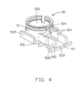
- FIG. 4 is a perspective view of a metal shell of the cable end connector of FIG. 1.
- FIG. 5 is a perspective, upside-down view of a retainer of the cable end connector of FIG. 1.
- FIG. 6 is a cross-sectional view taken along a line 6 - 6 of FIG. 2.
- a cable end connector in accordance with the present invention comprises a dielectric housing 10 , a terminal 40 , a metal shell 50 enclosing the housing 10 and the terminal 40 , a circular thin layer insulator 1 and a retainer 60 for securing an end portion of a coaxial cable 70 to the cable end connector.
- the dielectric housing 10 comprises a base portion 30 and a tubular portion 20 .
- the base portion 30 comprises a front circular portion 31 and a rear rectangular portion 32 extending rearwardly from the circular portion 31 .
- a pair of engaging blocks 33 protrude laterally from the circular portion 31 to abut against the shell 50 .
- a rearwardly exposed groove 34 is defined in a bottom of the base portion 30 .
- the tubular portion 20 axially and upwardly projects from the front circular portion 31 .
- a substantially rectangular passageway 21 is axially defined through the front circular portion 31 and the tubular portion 20 , and communicates with the groove 34 .
- the terminal 40 includes a bottom portion 41 and a pair of mating wings 43 .
- a pair of mating wings 43 extends upwardly from opposite lateral sides of the bottom portion 41 and projects toward each other for griping a mating of a complementary connector (not shown).
- a soldering tab 44 is bent downwardly from a rear side of the bottom portion 41 .
- a recess 441 is defined through the soldering tab 44 .
- the shell 50 is unitarily formed of a metal sheet and comprises a substantially cylindrical trunk portion 51 and a substantially planar portion 53 connected to the trunk portion 51 . It should be noted that, before bending, the planar portion 53 is oriented vertically below the trunk portion 51 .
- the trunk portion 51 has a pair of arms 513 rearwardly extending from a lower portion thereof. Each arm 513 has an elongate distal end 512 protruding inwardly for accommodating the coaxial cable 70 therebetween.
- the trunk portion 51 defines a hollow portion 515 therethrough for receiving the tubular portion 20 of the housing 10 .
- a pair of holding protrusions 514 are formed in a lower portion of the trunk portion 51 for interferentially cooperating with the pair of engaging blocks 33 of the housing 10 .
- the planar portion 53 has a front portion 531 and a rear portion 533 rearwardly extending from the front portion 531 beyond the distal ends 512 of the arms 513 for supporting the arms 513 and the rectangular portion 32 of the housing 10 .
- the front portion 531 supports the trunk portion 51 of the shell 50 and the circular portion 31 of the housing 10 .
- a pair of side walls 537 project from on opposite sides of the front portion 531 for interferentially engaging with the outer periphery of the trunk portion 51 .
- a pair of cuts 535 are respectively defined in opposite sides of the rear portion 533 .
- the circular thin layer insulator 1 is formed of a dielectric sheet.
- the circular thin layer insulator 1 can be formed of a dielectric material which is parasitically arranged on the front portion 531 of the metal shell 50 .
- the retainer 60 is conductive and comprises a planar top wall 61 and a strain relief 69 rearwardly extending from a rear edge of the top wall 61 for securely clamping the coaxial cable 70 .
- a contacting portion 62 is depressed from the top wall 61 and protrudes inwardly.
- a pair of locking tabs 63 respectively depend downwardly from opposite lateral sides of the top wall 61 for engaging with the cut 535 of the shell 50 .
- the coaxial cable 70 includes an inner conductor 71 , a conductive braiding layer 73 , an inner insulator 72 separating the inner conductor 71 and the braiding layer 73 , and an outer insulator 74 surrounding the braiding layer 73 .
- the cable end connector of the present invention is assembled as follows.
- the trunk portion 51 of the shell 50 encircles the tubular portion 20 of the housing 10 with the holding protrusions 514 abutting against the engaging blocks 33 .
- the arms 513 accommodate the rectangular portion 32 of the housing 10 therebetween.
- the circular thin layer insulator 1 is positioned between the front circular portion 31 of the housing 10 and the planar portion 53 of the shell 50 .
- the locking tabs 63 of the retainer 60 engage with the corresponding cuts 535 and abut against the bottom of the planar portion 53 , thereby fixedly retaining the arms 513 to an upper face of the planar portion 53 .
- the braiding layer 73 of the coaxial cable 70 is therefore surrounded by both the arms 513 and the top wall 61 of the retainer 60 .
- the shell 50 electrically connects with the braiding layer 73 by the arms 513 engaging with the braiding layer 73 and the retainer 60 electrically connects with the braiding layer 73 by the contacting portion 62 engaging with the braiding layer 73 , which makes the braiding layer 73 reliably grounded.
- the outer insulator 74 of the coaxial cable 70 is firmly retained in the strain relief 69 of the retainer 60 .
- the terminal 40 and the inner conductor 71 are insulated from the shell 50 by the covering of the circular thin layer insulator 1 .
- the circular thin layer insulator 1 prevents the terminal 40 and the inner conductor 71 of the coaxial cable 70 from touching the planar portion 53 of the shell 50 , thereby achieving a good insulation function.
- the thickness of the circular thin layer insulator 1 is also provided for matching the impedance of the cable end connector for a high frequency application. Furthermore, with the circular thin layer insulator 1 , the cable end connector has a low profile.
Landscapes
- Coupling Device And Connection With Printed Circuit (AREA)
Abstract
Description
- This application is a continuation-in-part of a co-pending U.S. patent application entitled “LOW PROFILE CABLE END CONNECTOR”, with application Ser. No. 10/118,223, filed on Apr. 5, 2002, invented by the same inventor, and assigned to the same assignee of the present invention.
- 1. Field of the Invention
- The present invention relates to a connector, and more particularly to a low profile cable end connector for high frequency application.
- 2. Description of the Prior Art
- Cable end connectors are often used for transmitting Radio-frequency (RF) signals. The cable end connector normally has a terminal received in a housing thereof to mate with a complementary connector, such as a header. Such a conventional cable end connector is, for example, disclosed in U.S. Pat. No. 5,322,453. The cable end connector includes a dielectric member holding a central terminal within an outer conductive shell. The dielectric member is substantially cylindrical and defines a coaxial passageway therein for receiving the terminal. A pair of small tabs projects from the terminal and abuts against an inner surface of the dielectric member, thereby retaining the terminal in the dielectric member. The outer conductive shell is bent at right angle to cover an opening of the passageway. However, because current cable end connector is very small, the tabs of the terminal of the small cable end connector are too tiny to retain the terminal in the dielectric member. By a relatively large mating force of the header, the terminal tends to be pushed out of the dielectric member to touch the conductive shell, resulting in an unreliable insulation function between the terminal and the conductive shell.
- In order to solve the above-mentioned problem, U.S. Pat. No. 6,508,668 discloses a conventional cable end connector. The cable end connector also includes a dielectric member holding a central terminal within an outer conductive shell. As disclosed in this patent, in assembly, an upper cover section of the dielectric member and a holder portion of the outer shell are bent substantially at a right angle to hold the terminal and an inner conductor of the coaxial cable within the dielectric member and to crimp the coaxial cable braiding to the outer conductive shell.
- As for its design, the dielectric member must be formed of a flexible material to possess a certain degree of resiliency, thereby ensuring it capable of being bent to the right angle without breakage. On the contrary, however, the flexible dielectric member may be not strong enough to securely hold the terminal therein. The terminal, therefore, tends to move with respect to the flexible dielectric member when the cable end connector mates/unmates with/from the header. The movement inevitably bends the terminal of the cable end connector or a contact of the header.
- Hence, an improved cable end connector is desired to overcome the above-mentioned problems of existing cable end connector.
- A main object of the present invention is to provide a cable end connector which is capable of reliably insulating a terminal from a metal shell thereof.
- Another object is to provide a cable end connector having a terminal reliably received in the housing thereof.
- A cable end connector according to the present invention comprises an insulative housing, a terminal received in the housing, a metal shell enclosing the housing, a circular thin layer insulator and a retainer attached to the shell for holding a coaxial cable therein. The insulative housing defines a passageway therethrough. The passageway has an end exposed to the metal shell. The terminal is received in the passageway of the housing for electrically engaging with a complementary connector. The metal shell comprises a planar portion covering the housing. The planar portion of metal shell faces the end of the passageway. The circular thin layer insulator is located between the end of the passageway of the housing and the planar portion of the metal shell, thereby insulating the terminal from the metal shell. The retainer is attached to the metal shell for retaining the metal shell to the housing.
- By such a design, the terminal is insulated from the metal shell by the covering of the circular thin layer insulator. When the terminal suffers from a large mating force of the header, the circular thin layer insulator prevents the terminal from touching the metal shell, thereby achieving a good insulation function. In addition, the cable end connector is capable of securely retaining the terminal therein.
- Other objects, advantages and novel features of the invention will become more apparent from the following detailed description when taken in conjunction with the accompanying drawings.
- FIG. 1 is an exploded view of a cable end connector according to the present invention and a coaxial cable.
- FIG. 2 is an assembled view of FIG. 1.
- FIG. 3 is a partial assembled, upside-down view of FIG. 1.
- FIG. 4 is a perspective view of a metal shell of the cable end connector of FIG. 1.
- FIG. 5 is a perspective, upside-down view of a retainer of the cable end connector of FIG. 1.
- FIG. 6 is a cross-sectional view taken along a line 6-6 of FIG. 2.
- Referring to the drawings and particularly to FIGS. 1 and 2, a cable end connector in accordance with the present invention comprises a
dielectric housing 10, aterminal 40, ametal shell 50 enclosing thehousing 10 and theterminal 40, a circularthin layer insulator 1 and aretainer 60 for securing an end portion of acoaxial cable 70 to the cable end connector. - The
dielectric housing 10 comprises abase portion 30 and atubular portion 20. Thebase portion 30 comprises a frontcircular portion 31 and a rearrectangular portion 32 extending rearwardly from thecircular portion 31. A pair ofengaging blocks 33 protrude laterally from thecircular portion 31 to abut against theshell 50. A rearwardly exposedgroove 34 is defined in a bottom of thebase portion 30. Thetubular portion 20 axially and upwardly projects from the frontcircular portion 31. A substantiallyrectangular passageway 21 is axially defined through the frontcircular portion 31 and thetubular portion 20, and communicates with thegroove 34. - The
terminal 40 includes abottom portion 41 and a pair ofmating wings 43. A pair ofmating wings 43 extends upwardly from opposite lateral sides of thebottom portion 41 and projects toward each other for griping a mating of a complementary connector (not shown). Asoldering tab 44 is bent downwardly from a rear side of thebottom portion 41. Arecess 441 is defined through thesoldering tab 44. - Referring to FIG. 4, the
shell 50 is unitarily formed of a metal sheet and comprises a substantiallycylindrical trunk portion 51 and a substantiallyplanar portion 53 connected to thetrunk portion 51. It should be noted that, before bending, theplanar portion 53 is oriented vertically below thetrunk portion 51. - The
trunk portion 51 has a pair ofarms 513 rearwardly extending from a lower portion thereof. Eacharm 513 has an elongatedistal end 512 protruding inwardly for accommodating thecoaxial cable 70 therebetween. Thetrunk portion 51 defines ahollow portion 515 therethrough for receiving thetubular portion 20 of thehousing 10. Preferably, a pair of holding protrusions 514 (shown in FIG. 6) are formed in a lower portion of thetrunk portion 51 for interferentially cooperating with the pair of engagingblocks 33 of thehousing 10. - The
planar portion 53 has afront portion 531 and arear portion 533 rearwardly extending from thefront portion 531 beyond the distal ends 512 of thearms 513 for supporting thearms 513 and therectangular portion 32 of thehousing 10. Thefront portion 531 supports thetrunk portion 51 of theshell 50 and thecircular portion 31 of thehousing 10. A pair ofside walls 537 project from on opposite sides of thefront portion 531 for interferentially engaging with the outer periphery of thetrunk portion 51. A pair ofcuts 535 are respectively defined in opposite sides of therear portion 533. - In this preferred embodiment of the present invention, the circular
thin layer insulator 1 is formed of a dielectric sheet. Alternatively, the circularthin layer insulator 1 can be formed of a dielectric material which is parasitically arranged on thefront portion 531 of themetal shell 50. - With reference to FIGS. 1 and 5, the
retainer 60 is conductive and comprises a planartop wall 61 and astrain relief 69 rearwardly extending from a rear edge of thetop wall 61 for securely clamping thecoaxial cable 70. A contactingportion 62 is depressed from thetop wall 61 and protrudes inwardly. A pair of lockingtabs 63 respectively depend downwardly from opposite lateral sides of thetop wall 61 for engaging with thecut 535 of theshell 50. - Particularly referring to FIG. 1, the
coaxial cable 70 includes aninner conductor 71, aconductive braiding layer 73, aninner insulator 72 separating theinner conductor 71 and thebraiding layer 73, and anouter insulator 74 surrounding thebraiding layer 73. - Referring to FIGS. 1-6, the cable end connector of the present invention is assembled as follows.
- (1) The contacting
wings 43 of the terminal 40 is inserted into thepassageway 21 through thegroove 34 of thehousing 10, abutting against corresponding inner walls (not labeled) of thepassageway 21. Thesoldering tab 44 of the terminal 40 is retained in thegroove 34. - (2) The
inner insulator 72 of thecoaxial cable 70 is inserted in thegroove 34, and theinner conductor 71 extends forwardly through therecess 441 of the terminal 40 and is soldered to thesoldering tab 44 and a lower surface of thebottom portion 41 of the terminal 40. - (3) The
trunk portion 51 of theshell 50 encircles thetubular portion 20 of thehousing 10 with the holdingprotrusions 514 abutting against the engaging blocks 33. Thearms 513 accommodate therectangular portion 32 of thehousing 10 therebetween. - (4) The circular
thin layer insulator 1 is positioned between the frontcircular portion 31 of thehousing 10 and theplanar portion 53 of theshell 50. - (4) The
planar portion 53 of theshell 50, which is originally oriented vertically downward, is now bent toward thetrunk portion 51 until theplanar portion 53 securely presses the circularthin layer insulator 1 to cover a lower opening of the passageway 2 defined in the bottom of thehousing 10. - (5) The locking
tabs 63 of theretainer 60 engage with thecorresponding cuts 535 and abut against the bottom of theplanar portion 53, thereby fixedly retaining thearms 513 to an upper face of theplanar portion 53. Thebraiding layer 73 of thecoaxial cable 70 is therefore surrounded by both thearms 513 and thetop wall 61 of theretainer 60. Theshell 50 electrically connects with thebraiding layer 73 by thearms 513 engaging with thebraiding layer 73 and theretainer 60 electrically connects with thebraiding layer 73 by the contactingportion 62 engaging with thebraiding layer 73, which makes thebraiding layer 73 reliably grounded. Theouter insulator 74 of thecoaxial cable 70 is firmly retained in thestrain relief 69 of theretainer 60. - By such a design, the terminal 40 and the
inner conductor 71 are insulated from theshell 50 by the covering of the circularthin layer insulator 1. When the terminal 40 suffers from a large mating force of the header, the circularthin layer insulator 1 prevents the terminal 40 and theinner conductor 71 of thecoaxial cable 70 from touching theplanar portion 53 of theshell 50, thereby achieving a good insulation function. In addition, the thickness of the circularthin layer insulator 1 is also provided for matching the impedance of the cable end connector for a high frequency application. Furthermore, with the circularthin layer insulator 1, the cable end connector has a low profile. - It is to be understood, however, that even though numerous characteristics and advantages of the present invention have been set forth in the foregoing description, together with details of the structure and function of the invention, the disclosure is illustrative only, and changes may be made in detail, especially in matters of shape, size, and arrangement of parts within the principles of the invention to the full extent indicated by the broad general meaning of the terms in which the appended claims are expressed.
Claims (15)
Priority Applications (3)
| Application Number | Priority Date | Filing Date | Title |
|---|---|---|---|
| US10/373,916 US6837743B2 (en) | 2002-04-05 | 2003-02-24 | Cable end connector having good insulation function |
| CN 03263660 CN2629280Y (en) | 2003-02-24 | 2003-05-19 | Cable connector |
| TW92209545U TW568462U (en) | 2003-02-24 | 2003-05-23 | Cable end connector having good insulation function |
Applications Claiming Priority (2)
| Application Number | Priority Date | Filing Date | Title |
|---|---|---|---|
| US10/118,223 US6572407B1 (en) | 2002-04-05 | 2002-04-05 | Low profile cable end connector |
| US10/373,916 US6837743B2 (en) | 2002-04-05 | 2003-02-24 | Cable end connector having good insulation function |
Related Parent Applications (1)
| Application Number | Title | Priority Date | Filing Date |
|---|---|---|---|
| US10/118,223 Continuation-In-Part US6572407B1 (en) | 2002-04-05 | 2002-04-05 | Low profile cable end connector |
Publications (2)
| Publication Number | Publication Date |
|---|---|
| US20030190824A1 true US20030190824A1 (en) | 2003-10-09 |
| US6837743B2 US6837743B2 (en) | 2005-01-04 |
Family
ID=46204752
Family Applications (1)
| Application Number | Title | Priority Date | Filing Date |
|---|---|---|---|
| US10/373,916 Expired - Fee Related US6837743B2 (en) | 2002-04-05 | 2003-02-24 | Cable end connector having good insulation function |
Country Status (1)
| Country | Link |
|---|---|
| US (1) | US6837743B2 (en) |
Cited By (4)
| Publication number | Priority date | Publication date | Assignee | Title |
|---|---|---|---|---|
| US8342860B1 (en) * | 2011-09-20 | 2013-01-01 | The United States Of America As Represented By The Secretary Of The Navy | Interface board connector |
| US20130280948A1 (en) * | 2012-04-19 | 2013-10-24 | Hirose Electric Co., Ltd. | Electrical connector |
| US9502834B2 (en) * | 2015-01-28 | 2016-11-22 | Dai-Ichi Seiko Co., Ltd. | Coaxial-type electric connector |
| US20210320464A1 (en) * | 2019-05-10 | 2021-10-14 | Murata Manufacturing Co., Ltd. | Ground coupling structure in coaxial connector set |
Families Citing this family (17)
| Publication number | Priority date | Publication date | Assignee | Title |
|---|---|---|---|---|
| JP4053950B2 (en) * | 2003-08-08 | 2008-02-27 | ヒロセ電機株式会社 | Coaxial connector, and connector and notebook computer used therefor |
| US20050064734A1 (en) * | 2003-09-24 | 2005-03-24 | Shih-Tung Chang | Cable end connector assembly |
| JP4139782B2 (en) * | 2004-01-20 | 2008-08-27 | ホシデン株式会社 | Connector for coaxial cable |
| US6916201B1 (en) * | 2004-03-03 | 2005-07-12 | Speed Tech Corp. | Micro coaxial cable connecting device |
| TWM270525U (en) * | 2004-10-29 | 2005-07-11 | Advanced Connectek Inc | An improved terminal structure of a coaxial connector |
| US7747071B2 (en) * | 2005-10-27 | 2010-06-29 | Hewlett-Packard Development Company, L.P. | Detecting and correcting peteye |
| US8064694B2 (en) * | 2006-06-21 | 2011-11-22 | Hewlett-Packard Development Company, L.P. | Nonhuman animal integument pixel classification |
| US7351067B2 (en) * | 2006-08-09 | 2008-04-01 | Speed Tech Corp. | Coaxial cable connecting apparatus |
| WO2008146521A1 (en) * | 2007-06-01 | 2008-12-04 | Murata Manufacturing Co., Ltd. | Coaxial connector |
| US7384307B1 (en) * | 2007-08-07 | 2008-06-10 | Ezconn Corporation | Coaxial cable end connector |
| US7540774B1 (en) * | 2008-04-28 | 2009-06-02 | Cheng Uei Precision Industry Co., Ltd. | Coaxial connector |
| TWM365590U (en) * | 2009-05-27 | 2009-09-21 | Advanced Connectek Inc | Coaxial micro-connector |
| US7980894B1 (en) * | 2010-08-23 | 2011-07-19 | Tyco Electronics Corporation | Coaxial connector with a cable receptor with an outer contact |
| JP5522410B2 (en) * | 2011-10-12 | 2014-06-18 | 第一精工株式会社 | Coaxial connector device |
| JP2018113176A (en) * | 2017-01-12 | 2018-07-19 | 住友電装株式会社 | Shield conductive path |
| CN216850571U (en) * | 2021-12-20 | 2022-06-28 | 东莞立讯技术有限公司 | Cable connector and cable connector assembly |
| WO2023210747A1 (en) * | 2022-04-28 | 2023-11-02 | I-Pex株式会社 | Electric connector, cable harness, and method for assembling cable harness |
Citations (7)
| Publication number | Priority date | Publication date | Assignee | Title |
|---|---|---|---|---|
| US5263877A (en) * | 1991-03-12 | 1993-11-23 | Hirose Electric Co., Ltd. | L-shaped coaxial cable connector |
| US5322453A (en) * | 1992-11-25 | 1994-06-21 | M/A-Com Omni Spectra, Inc. | RF connector jack and plug assembly |
| US5569049A (en) * | 1993-10-06 | 1996-10-29 | Japan Aviation Electronics Industry, Limited | Coaxial connector plug having sheath penetrating contacts and receptacle for receiving the same |
| US5772470A (en) * | 1996-06-03 | 1998-06-30 | Smk Corporation | Coaxial connector |
| US5879190A (en) * | 1995-04-18 | 1999-03-09 | Murata Manufacturing Co., Ltd. | Coaxial connector |
| US6305980B2 (en) * | 1999-03-18 | 2001-10-23 | Hon Hai Precision Ind. Co., Ltd. | Cable end connector having accurately positioned connection terminal therein |
| US6508668B1 (en) * | 1999-07-30 | 2003-01-21 | Hirose Electric Co., Ltd. | L-shaped coaxial connector and terminal for the same |
Family Cites Families (1)
| Publication number | Priority date | Publication date | Assignee | Title |
|---|---|---|---|---|
| JPH06314924A (en) | 1993-04-19 | 1994-11-08 | Wireless Access Inc | Partly shorted microstrip antenna |
-
2003
- 2003-02-24 US US10/373,916 patent/US6837743B2/en not_active Expired - Fee Related
Patent Citations (7)
| Publication number | Priority date | Publication date | Assignee | Title |
|---|---|---|---|---|
| US5263877A (en) * | 1991-03-12 | 1993-11-23 | Hirose Electric Co., Ltd. | L-shaped coaxial cable connector |
| US5322453A (en) * | 1992-11-25 | 1994-06-21 | M/A-Com Omni Spectra, Inc. | RF connector jack and plug assembly |
| US5569049A (en) * | 1993-10-06 | 1996-10-29 | Japan Aviation Electronics Industry, Limited | Coaxial connector plug having sheath penetrating contacts and receptacle for receiving the same |
| US5879190A (en) * | 1995-04-18 | 1999-03-09 | Murata Manufacturing Co., Ltd. | Coaxial connector |
| US5772470A (en) * | 1996-06-03 | 1998-06-30 | Smk Corporation | Coaxial connector |
| US6305980B2 (en) * | 1999-03-18 | 2001-10-23 | Hon Hai Precision Ind. Co., Ltd. | Cable end connector having accurately positioned connection terminal therein |
| US6508668B1 (en) * | 1999-07-30 | 2003-01-21 | Hirose Electric Co., Ltd. | L-shaped coaxial connector and terminal for the same |
Cited By (6)
| Publication number | Priority date | Publication date | Assignee | Title |
|---|---|---|---|---|
| US8342860B1 (en) * | 2011-09-20 | 2013-01-01 | The United States Of America As Represented By The Secretary Of The Navy | Interface board connector |
| US20130280948A1 (en) * | 2012-04-19 | 2013-10-24 | Hirose Electric Co., Ltd. | Electrical connector |
| US9184535B2 (en) * | 2012-04-19 | 2015-11-10 | Hirose Electric Co., Ltd. | Electrical connector |
| US9502834B2 (en) * | 2015-01-28 | 2016-11-22 | Dai-Ichi Seiko Co., Ltd. | Coaxial-type electric connector |
| US20210320464A1 (en) * | 2019-05-10 | 2021-10-14 | Murata Manufacturing Co., Ltd. | Ground coupling structure in coaxial connector set |
| US11870188B2 (en) * | 2019-05-10 | 2024-01-09 | Murata Manufacturing Co., Ltd. | Ground coupling structure in coaxial connector set |
Also Published As
| Publication number | Publication date |
|---|---|
| US6837743B2 (en) | 2005-01-04 |
Similar Documents
| Publication | Publication Date | Title |
|---|---|---|
| US6837743B2 (en) | Cable end connector having good insulation function | |
| US6572407B1 (en) | Low profile cable end connector | |
| US6482045B2 (en) | Connector socket, connector plug and connector assembly | |
| US7762841B2 (en) | Coaxial cable connector | |
| US7833054B2 (en) | Connector | |
| US8894444B2 (en) | Coaxial electrical connector and coaxial electrical connector assembly including a tubular contact for reducing the height and improving the retention strength against mating or removal | |
| US5180317A (en) | Angled electrical connector | |
| US6966797B2 (en) | High-speed cable assembly | |
| US6305980B2 (en) | Cable end connector having accurately positioned connection terminal therein | |
| JP4761320B2 (en) | connector | |
| US7540774B1 (en) | Coaxial connector | |
| US6793520B1 (en) | Cable end connector assembly with strain relief | |
| US6319030B1 (en) | Switching receptacle connector | |
| KR20180028386A (en) | Electrical connector | |
| US6361383B1 (en) | Cable end connector reliably positioning a shell | |
| US6371806B1 (en) | Cable end connector having accurately positioned connection terminal therein | |
| JPH07192819A (en) | Coaxial connector | |
| US6447335B1 (en) | Cable end connector | |
| US6340312B1 (en) | Cable end connector having a complete EMI shielding | |
| JP2008532204A (en) | Coaxial cable connector with improved shield | |
| US6709282B2 (en) | Waterproof connector | |
| US7232341B2 (en) | Connector in which a shell can be readily assembled to a connector housing | |
| JP5229924B2 (en) | connector | |
| US20060258212A1 (en) | Power connector with improved contacts | |
| US6416357B1 (en) | Cable end connector with low profile after assembly |
Legal Events
| Date | Code | Title | Description |
|---|---|---|---|
| AS | Assignment |
Owner name: HON HAI PRECISION IND. CO., LTD., TAIWAN Free format text: ASSIGNMENT OF ASSIGNORS INTEREST;ASSIGNOR:KO, DAVID TSO-CHIN;REEL/FRAME:013818/0482 Effective date: 20030220 |
|
| FPAY | Fee payment |
Year of fee payment: 4 |
|
| FPAY | Fee payment |
Year of fee payment: 8 |
|
| REMI | Maintenance fee reminder mailed | ||
| LAPS | Lapse for failure to pay maintenance fees | ||
| STCH | Information on status: patent discontinuation |
Free format text: PATENT EXPIRED DUE TO NONPAYMENT OF MAINTENANCE FEES UNDER 37 CFR 1.362 |
|
| STCH | Information on status: patent discontinuation |
Free format text: PATENT EXPIRED DUE TO NONPAYMENT OF MAINTENANCE FEES UNDER 37 CFR 1.362 |
|
| FP | Lapsed due to failure to pay maintenance fee |
Effective date: 20170104 |