US20030190512A1 - Fuel cell system and its startup control - Google Patents
Fuel cell system and its startup control Download PDFInfo
- Publication number
- US20030190512A1 US20030190512A1 US10/380,432 US38043203A US2003190512A1 US 20030190512 A1 US20030190512 A1 US 20030190512A1 US 38043203 A US38043203 A US 38043203A US 2003190512 A1 US2003190512 A1 US 2003190512A1
- Authority
- US
- United States
- Prior art keywords
- fuel cell
- cell stack
- cooling water
- pressure
- temperature
- Prior art date
- Legal status (The legal status is an assumption and is not a legal conclusion. Google has not performed a legal analysis and makes no representation as to the accuracy of the status listed.)
- Granted
Links
- 239000000446 fuel Substances 0.000 title claims abstract description 166
- 239000000498 cooling water Substances 0.000 claims abstract description 104
- XLYOFNOQVPJJNP-UHFFFAOYSA-N water Substances O XLYOFNOQVPJJNP-UHFFFAOYSA-N 0.000 claims abstract description 77
- 239000012528 membrane Substances 0.000 claims description 29
- 239000002737 fuel gas Substances 0.000 claims description 22
- 239000007789 gas Substances 0.000 claims description 14
- 230000006870 function Effects 0.000 claims description 12
- 238000000034 method Methods 0.000 claims description 9
- 239000003570 air Substances 0.000 claims description 6
- 230000007423 decrease Effects 0.000 claims description 6
- 239000012530 fluid Substances 0.000 claims description 6
- 230000001965 increasing effect Effects 0.000 claims description 5
- 238000012545 processing Methods 0.000 description 14
- 238000010276 construction Methods 0.000 description 8
- UFHFLCQGNIYNRP-UHFFFAOYSA-N Hydrogen Chemical compound [H][H] UFHFLCQGNIYNRP-UHFFFAOYSA-N 0.000 description 6
- 239000001257 hydrogen Substances 0.000 description 6
- 229910052739 hydrogen Inorganic materials 0.000 description 6
- 239000007800 oxidant agent Substances 0.000 description 6
- 238000001816 cooling Methods 0.000 description 4
- 238000010438 heat treatment Methods 0.000 description 4
- OKKJLVBELUTLKV-UHFFFAOYSA-N Methanol Chemical compound OC OKKJLVBELUTLKV-UHFFFAOYSA-N 0.000 description 3
- 230000008859 change Effects 0.000 description 3
- 238000006243 chemical reaction Methods 0.000 description 3
- 238000010586 diagram Methods 0.000 description 3
- 238000002407 reforming Methods 0.000 description 3
- 230000008901 benefit Effects 0.000 description 2
- 230000005494 condensation Effects 0.000 description 2
- 238000009833 condensation Methods 0.000 description 2
- VNWKTOKETHGBQD-UHFFFAOYSA-N methane Chemical compound C VNWKTOKETHGBQD-UHFFFAOYSA-N 0.000 description 2
- 230000035515 penetration Effects 0.000 description 2
- ATJFFYVFTNAWJD-UHFFFAOYSA-N Tin Chemical compound [Sn] ATJFFYVFTNAWJD-UHFFFAOYSA-N 0.000 description 1
- QVGXLLKOCUKJST-UHFFFAOYSA-N atomic oxygen Chemical compound [O] QVGXLLKOCUKJST-UHFFFAOYSA-N 0.000 description 1
- 238000007664 blowing Methods 0.000 description 1
- 238000009529 body temperature measurement Methods 0.000 description 1
- 239000006185 dispersion Substances 0.000 description 1
- 238000003487 electrochemical reaction Methods 0.000 description 1
- 230000002708 enhancing effect Effects 0.000 description 1
- 238000002474 experimental method Methods 0.000 description 1
- 239000003502 gasoline Substances 0.000 description 1
- 238000005259 measurement Methods 0.000 description 1
- 238000012986 modification Methods 0.000 description 1
- 230000004048 modification Effects 0.000 description 1
- 239000003345 natural gas Substances 0.000 description 1
- 239000001301 oxygen Substances 0.000 description 1
- 229910052760 oxygen Inorganic materials 0.000 description 1
- 239000011148 porous material Substances 0.000 description 1
- 238000010248 power generation Methods 0.000 description 1
- 230000004044 response Effects 0.000 description 1
- 238000007789 sealing Methods 0.000 description 1
Images


Classifications
-
- H—ELECTRICITY
- H01—ELECTRIC ELEMENTS
- H01M—PROCESSES OR MEANS, e.g. BATTERIES, FOR THE DIRECT CONVERSION OF CHEMICAL ENERGY INTO ELECTRICAL ENERGY
- H01M8/00—Fuel cells; Manufacture thereof
- H01M8/04—Auxiliary arrangements, e.g. for control of pressure or for circulation of fluids
- H01M8/04298—Processes for controlling fuel cells or fuel cell systems
- H01M8/04694—Processes for controlling fuel cells or fuel cell systems characterised by variables to be controlled
- H01M8/04746—Pressure; Flow
- H01M8/04768—Pressure; Flow of the coolant
-
- H—ELECTRICITY
- H01—ELECTRIC ELEMENTS
- H01M—PROCESSES OR MEANS, e.g. BATTERIES, FOR THE DIRECT CONVERSION OF CHEMICAL ENERGY INTO ELECTRICAL ENERGY
- H01M8/00—Fuel cells; Manufacture thereof
- H01M8/02—Details
- H01M8/0202—Collectors; Separators, e.g. bipolar separators; Interconnectors
- H01M8/023—Porous and characterised by the material
-
- H—ELECTRICITY
- H01—ELECTRIC ELEMENTS
- H01M—PROCESSES OR MEANS, e.g. BATTERIES, FOR THE DIRECT CONVERSION OF CHEMICAL ENERGY INTO ELECTRICAL ENERGY
- H01M8/00—Fuel cells; Manufacture thereof
- H01M8/04—Auxiliary arrangements, e.g. for control of pressure or for circulation of fluids
- H01M8/04007—Auxiliary arrangements, e.g. for control of pressure or for circulation of fluids related to heat exchange
- H01M8/04067—Heat exchange or temperature measuring elements, thermal insulation, e.g. heat pipes, heat pumps, fins
- H01M8/04074—Heat exchange unit structures specially adapted for fuel cell
-
- H—ELECTRICITY
- H01—ELECTRIC ELEMENTS
- H01M—PROCESSES OR MEANS, e.g. BATTERIES, FOR THE DIRECT CONVERSION OF CHEMICAL ENERGY INTO ELECTRICAL ENERGY
- H01M8/00—Fuel cells; Manufacture thereof
- H01M8/04—Auxiliary arrangements, e.g. for control of pressure or for circulation of fluids
- H01M8/04223—Auxiliary arrangements, e.g. for control of pressure or for circulation of fluids during start-up or shut-down; Depolarisation or activation, e.g. purging; Means for short-circuiting defective fuel cells
- H01M8/04225—Auxiliary arrangements, e.g. for control of pressure or for circulation of fluids during start-up or shut-down; Depolarisation or activation, e.g. purging; Means for short-circuiting defective fuel cells during start-up
-
- H—ELECTRICITY
- H01—ELECTRIC ELEMENTS
- H01M—PROCESSES OR MEANS, e.g. BATTERIES, FOR THE DIRECT CONVERSION OF CHEMICAL ENERGY INTO ELECTRICAL ENERGY
- H01M8/00—Fuel cells; Manufacture thereof
- H01M8/04—Auxiliary arrangements, e.g. for control of pressure or for circulation of fluids
- H01M8/04223—Auxiliary arrangements, e.g. for control of pressure or for circulation of fluids during start-up or shut-down; Depolarisation or activation, e.g. purging; Means for short-circuiting defective fuel cells
- H01M8/04253—Means for solving freezing problems
-
- H—ELECTRICITY
- H01—ELECTRIC ELEMENTS
- H01M—PROCESSES OR MEANS, e.g. BATTERIES, FOR THE DIRECT CONVERSION OF CHEMICAL ENERGY INTO ELECTRICAL ENERGY
- H01M8/00—Fuel cells; Manufacture thereof
- H01M8/04—Auxiliary arrangements, e.g. for control of pressure or for circulation of fluids
- H01M8/04298—Processes for controlling fuel cells or fuel cell systems
- H01M8/043—Processes for controlling fuel cells or fuel cell systems applied during specific periods
- H01M8/04302—Processes for controlling fuel cells or fuel cell systems applied during specific periods applied during start-up
-
- H—ELECTRICITY
- H01—ELECTRIC ELEMENTS
- H01M—PROCESSES OR MEANS, e.g. BATTERIES, FOR THE DIRECT CONVERSION OF CHEMICAL ENERGY INTO ELECTRICAL ENERGY
- H01M8/00—Fuel cells; Manufacture thereof
- H01M8/04—Auxiliary arrangements, e.g. for control of pressure or for circulation of fluids
- H01M8/04298—Processes for controlling fuel cells or fuel cell systems
- H01M8/04313—Processes for controlling fuel cells or fuel cell systems characterised by the detection or assessment of variables; characterised by the detection or assessment of failure or abnormal function
- H01M8/0432—Temperature; Ambient temperature
- H01M8/04365—Temperature; Ambient temperature of other components of a fuel cell or fuel cell stacks
-
- H—ELECTRICITY
- H01—ELECTRIC ELEMENTS
- H01M—PROCESSES OR MEANS, e.g. BATTERIES, FOR THE DIRECT CONVERSION OF CHEMICAL ENERGY INTO ELECTRICAL ENERGY
- H01M8/00—Fuel cells; Manufacture thereof
- H01M8/04—Auxiliary arrangements, e.g. for control of pressure or for circulation of fluids
- H01M8/04298—Processes for controlling fuel cells or fuel cell systems
- H01M8/04313—Processes for controlling fuel cells or fuel cell systems characterised by the detection or assessment of variables; characterised by the detection or assessment of failure or abnormal function
- H01M8/0438—Pressure; Ambient pressure; Flow
- H01M8/04388—Pressure; Ambient pressure; Flow of anode reactants at the inlet or inside the fuel cell
-
- H—ELECTRICITY
- H01—ELECTRIC ELEMENTS
- H01M—PROCESSES OR MEANS, e.g. BATTERIES, FOR THE DIRECT CONVERSION OF CHEMICAL ENERGY INTO ELECTRICAL ENERGY
- H01M8/00—Fuel cells; Manufacture thereof
- H01M8/04—Auxiliary arrangements, e.g. for control of pressure or for circulation of fluids
- H01M8/04298—Processes for controlling fuel cells or fuel cell systems
- H01M8/04313—Processes for controlling fuel cells or fuel cell systems characterised by the detection or assessment of variables; characterised by the detection or assessment of failure or abnormal function
- H01M8/0438—Pressure; Ambient pressure; Flow
- H01M8/04395—Pressure; Ambient pressure; Flow of cathode reactants at the inlet or inside the fuel cell
-
- H—ELECTRICITY
- H01—ELECTRIC ELEMENTS
- H01M—PROCESSES OR MEANS, e.g. BATTERIES, FOR THE DIRECT CONVERSION OF CHEMICAL ENERGY INTO ELECTRICAL ENERGY
- H01M8/00—Fuel cells; Manufacture thereof
- H01M8/04—Auxiliary arrangements, e.g. for control of pressure or for circulation of fluids
- H01M8/04298—Processes for controlling fuel cells or fuel cell systems
- H01M8/04313—Processes for controlling fuel cells or fuel cell systems characterised by the detection or assessment of variables; characterised by the detection or assessment of failure or abnormal function
- H01M8/0438—Pressure; Ambient pressure; Flow
- H01M8/04417—Pressure; Ambient pressure; Flow of the coolant
-
- Y—GENERAL TAGGING OF NEW TECHNOLOGICAL DEVELOPMENTS; GENERAL TAGGING OF CROSS-SECTIONAL TECHNOLOGIES SPANNING OVER SEVERAL SECTIONS OF THE IPC; TECHNICAL SUBJECTS COVERED BY FORMER USPC CROSS-REFERENCE ART COLLECTIONS [XRACs] AND DIGESTS
- Y02—TECHNOLOGIES OR APPLICATIONS FOR MITIGATION OR ADAPTATION AGAINST CLIMATE CHANGE
- Y02E—REDUCTION OF GREENHOUSE GAS [GHG] EMISSIONS, RELATED TO ENERGY GENERATION, TRANSMISSION OR DISTRIBUTION
- Y02E60/00—Enabling technologies; Technologies with a potential or indirect contribution to GHG emissions mitigation
- Y02E60/30—Hydrogen technology
- Y02E60/50—Fuel cells
Definitions
- This invention relates to a fuel cell system, and more particularly to startup control when a fuel cell system is started from a low temperature state.
- a fuel cell system transforms the energy of fuel, directly into electrical energy.
- JP8-106914A published by the Japanese Patent Office in 1996
- fuel gas containing hydrogen is supplied to the anode and an oxidizing agent gas containing oxygen is supplied to the cathode.
- Electrical energy is then extracted from the electrodes, using the electrochemical reactions produced on the surface of the membrane electrode, i.e.,
- the fuel gas supplied to the anode may be supplied directly from a hydrogen storage device, or fuel containing hydrogen may be reformed, and the reformed hydrogen-containing gas supplied to the anode.
- the fuel containing hydrogen may be natural gas, methanol or gasoline, and the oxidizing agent gas supplied to the cathode is generally air.
- the fuel gas and air introduced into the fuel cell is humidified.
- water is used for reforming. Therefore, in order to use the fuel cell for vehicles, a water balance must be maintained within the fuel cell system including the fuel cell or reforming device. This is because the practicality of a fuel cell vehicle will fall remarkably if water runs short and it becomes necessary to supply pure water periodically.
- water clogging When starting the fuel cell system at low temperature, the water generated inside the fuel cell and the moisture in the fuel and air condense inside the fuel cell, and may block the fuel and air passage, which is called “water clogging.” Water clogging reduces the efficiency of the fuel cell, and in particular, water clogging which occurs during startup lengthens the warm-up time of the fuel cell. As the frequency of startup operations is high in vehicles, the lengthening of the warm-up time of the fuel cell system reduces the usability of the fuel cell vehicle.
- One of the methods of resolving water clogging is the blowing away of the condensed water by increasing the pressure of the fuel gas or air.
- gas or air is delivered to the fuel cell at higher than ordinary operating pressure, the membrane electrode inside the fuel cell or the durability of the sealing will be degraded, the performance of the fuel cell will be reduced and its life will be shortened.
- startup operations may be performed from hundreds of times to thousands of times, so the above decline of performance is remarkable.
- the ability to vary the pressure of fuel gas and air makes the system construction complicated.
- Another method is to heat the fuel cell stack itself.
- the heating of the fuel cell stack makes the system complex. If the energy required for heating becomes large, the fuel economy of the vehicle decreases. Further, the time required for heating is too long for the vehicle.
- this invention provides a fuel cell system, comprising a fuel cell stack wherein a cooling water passage and an electrode are connected via a porous plate through which water can pass, a pressure adjusting device which adjusts the pressure of cooling water in the cooling water passage, and a controller.
- the controller functions to determine whether warmup of the fuel cell stack is complete based on the running state of the fuel cell stack, and before warmup of the fuel cell stack is complete, control the pressure adjusting device to decrease the cooling water pressure lower than the cooling water pressure after warmup is complete.
- this invention provides a startup method for a fuel cell system including a fuel cell stack wherein a cooling water passage and an electrode are connected via a porous plate through which water can pass and a pressure adjusting device which adjusts the pressure of cooling water in the cooling water passage, the method comprising determining whether warmup of the fuel cell stack is complete based on the running state of the fuel cell stack, and before warmup of the fuel cell stack is complete, controlling the pressure adjusting device to decrease the cooling water pressure lower than the cooling water pressure after warmup is complete.
- FIG. 1 is a block diagram of a fuel cell system relating to this invention.
- FIG. 2 is a flowchart showing the startup processing of the fuel cell system.
- FIG. 3 is a flowchart showing the startup processing taking the humidification state of a membrane electrode into consideration.
- FIG. 4 is similar to FIG. 1, but is a block diagram of a fuel cell system according to the second embodiment.
- FIG. 5 is a flowchart showing the startup processing according to the second embodiment.
- FIG. 6 is similar to FIG. 1, but is a block diagram of a fuel cell system according to the third embodiment.
- FIG. 7 is a flowchart showing the startup processing according to the third embodiment.
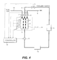
- a fuel cell system relating to this invention is provided with a fuel cell stack 1 comprising plural cells c1, c2, . . . , cn, pressure sensors 5 , 6 , 7 , a cooling water pump 12 , a cooling water tank 13 , a heat exchanger 14 and a controller 16 .
- a temperature sensor 15 for measuring the internal temperature Tsin of the fuel cell stack 1 is installed inside the fuel cell stack 1 . Measurement signals from these sensors are input into the controller 16 .
- Pressure sensors 5 , 6 , 7 measure the pressure in an air passage 8 which supplies air, a cooling water passage 9 which supplies cooling water and a fuel gas passage 10 which supplies fuel gas to the fuel cell stack 1 , in the vicinity of the inlet to the fuel cell stack 1 .
- the controller 16 comprises one, two or more microprocessors, a memory and an input/output interface.
- the controller 16 calculates a pressure difference ⁇ P between the cooling water passage 9 and electrodes, a cathode 2 and anode 3 at the inlet of the fuel cell stack 1 , from the signals from the pressure sensors 5 , 6 , 7 .
- the controller 16 determines a pressure Pcw of cooling water according to the internal temperature Tsin of the fuel cell stack 1 detected by the temperature sensor 15 , and controls the opening of a pressure reducing valve 11 and the rotation speed of the cooling water pump 12 so that a determined cooling water pressure Pcw is realized.
- the pressure Pcw of cooling water is controlled to be lower than the pressure Pnormal used in the steady state after warmup is complete. In this way, the water condensed in the cathode 2 and anode 3 can be made to flow into the cooling water passage 9 efficiently using the pressure difference via the holes in the porous plate 4 , and water clogging can be prevented.
- the cooling performance of the fuel cell stack 1 falls due to the lowering of the cooling water pressure Pcw.
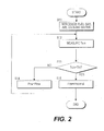
- FIG. 2 is a flowchart showing startup processing, and this is performed at a predetermined time, for example every 10 milliseconds, by the controller 16 .
- step S 11 fuel gas, air and cooling water start to be introduced to the fuel cell stack 1 .
- a step S 12 the internal temperature Tsin of the fuel cell stack 1 is measured.
- a step S 13 the measured internal temperature Tsin and the predetermined temperature Tth are compared.
- the predetermined temperature Tth is set according to the shape of the gas, air and cooling water passages, and the construction of the system. For example, it is set to the lowest temperature of the temperatures at which water clogging by the water condensed in the cathode 2 and anode 3 of the fuel cell stack 1 does not occur.
- the predetermined temperature Tth is set lower than the running temperature (about 60° C.-70° C.) of the fuel cell stack 1 . From experiment, it was found that water clogging does not occur above 40° C., and it was possible to run the vehicle by setting the cooling water pressure Pcw to the pressure Pnormal, so the predetermined temperature Tth was set to 40° C.
- step S 14 the water pressure Pcw is controlled to a predetermined low pressure power Plow, and the water condensed in the cathode 2 and anode 3 is made to flow out to the cooling water passage 9 .
- the cooling water pressure Pcw is preferred to make the cooling water pressure Pcw as low as possible relative to the cathode 2 and anode 3 .
- the differential pressure ⁇ P between the cooling water passage 9 and the electrodes 2 , 3 (cathode 2 and anode 3 ) becomes too large, fuel gas or oxidizing agent gas penetrates the cooling water passage 9 . If the differential pressure ⁇ P is further increased, the internal structure of the membrane electrode or cell may break down.
- the differential pressure ⁇ P between the cooling water passage 9 and the electrodes 2 , 3 is controlled so that the pressure is higher than the minimum value of the pressure at which fuel gas or oxidizing agent gas penetrates the cooling water passage 9 .
- the cooling water pressure Pcw is controlled to the pressure Pnormal normally used in steady running. Thereafter, the cooling water pressure Pcw is controlled to this ordinary pressure Pnormal, and the cooling performance of the fuel cell stack 1 is ensured.
- the differential pressure ⁇ P between the cooling water passage 9 and the electrodes 2 , 3 (cathode 2 and anode 3 ) is calculated, and the minimum of the cooling water pressure Pcw is set based thereon.
- the pressure value for low cooling water pressure operation (fixed value) may be predefined, and the cooling water pressure Pcw changed over to this preset value immediately in the step S 14 when low cooling water pressure running is performed.
- the humidification state of the membrane electrode is detected, and when the water content of the membrane electrode is smaller than a predetermined value, the pressure Pcw of the cooling water passage 9 is controlled to a second low pressure Plow2(Plow ⁇ Plow2 ⁇ Pnormal) which is lower than the normal running pressure Pnormal and higher than the pressure Plow set in the step S 14 .
- FIG. 3 is a flowchart showing the startup processing when taking the humidification state of the membrane electrode into consideration. Steps S 16 -S 18 are added to what was shown in FIG. 2.
- the humidification state of the membrane electrode is detected in the step S 16 .
- the humidification state of the membrane electrode can be predicted from the state change of the fuel cell stack 1 such as the change of electromotive force and the reserved water amount in the water tank 13 . More specifically, to predict this more directly, the temperature is detected for every cell forming the fuel cell stack 1 , the temperature distribution of cells is measured as shown in the embodiment described below, and the prediction is based thereon.
- step S 17 When it is determined in the step S 17 that humidification of the membrane electrode is not sufficient, the routine proceeds to the step S 18 , and the pressure Pcw of the cooling water passage 9 is controlled to the pressure Plow2 which is lower than the normal running pressure Pnormal and higher than the pressure set in the step S 14 .
- FIG. 4 shows the construction of a fuel cell system of the second embodiment. Temperature sensors 21 are installed which measure the temperatures in each cell c1, c2, . . . , cn of the fuel cell stack 1 , which is a difference from the first embodiment. For convenience, only three sensors 21 have been shown in FIG. 3, but there may be a larger or smaller number of the sensors 21 according to the number of the cells.
- the startup processings of the system performed by the controller 16 is also different.
- the controller 16 predicts water clogging from the temperature distribution of the cells, and performs pressure control of cooling water.
- the average of the cell temperatures is calculated, and the cooling water pressure Pcw is also controlled based on the differential pressure ⁇ P between the cooling water and the electrodes 2 , 3 (cathode 2 and anode 3 ) at the inlet of the fuel cell stack, and the average Tcelave of cell temperature.
- the controller 16 predicts water clogging from the dispersion (bias) in the distribution of the cell temperatures. For example, there is a bias in a temperature distribution such as when the temperature of some cells is low and the possibility of water clogging is predicted, the pressure Pcw of cooling water is immediately reduced to the minimum valve Plow of pressure at which penetration of fuel gas or oxidizing agent gas into the cooling water passage 9 does not take place, and the outflow efficiency of water from the cathode 2 and anode 3 to the cooling water passage 9 is increased to the maximum so as to rapidly eliminate any water clogging.
- bias a temperature distribution such as when the temperature of some cells is low and the possibility of water clogging is predicted
- the pressure Pcw of cooling water is immediately reduced to the minimum valve Plow of pressure at which penetration of fuel gas or oxidizing agent gas into the cooling water passage 9 does not take place, and the outflow efficiency of water from the cathode 2 and anode 3 to the cooling water passage 9 is increased to the maximum so as to rapidly eliminate any water clogging
- FIG. 5 is a flowchart showing startup processing of the fuel cell system, and is performed at a predetermined time, for example every 10 milliseconds, by the controller 16 .
- a step S 21 introduction of fuel gas, air and cooling water to the fuel cell stack 1 is started.
- a step S 22 the temperatures Tcel1, Tcel2, . . . , Tceln of the cells c1, c2, . . . , cn of the fuel cell stack 1 , are measured.
- a step S 23 water clogging is predicted from the distribution of cell temperature.
- the routine proceeds to a step S 24 , and the cooling water pressure Pcw is set to the minimum pressure Plow.
- the minimum pressure Plow is the minimum value of pressure at which penetration of fuel gas or oxidizing agent gas into the cooling water passage 9 does not take place, and is set based on the differential pressure ⁇ P between the cooling water passage 9 and the electrodes 2 , 3 as in the preceding embodiment.
- a step S 26 the average temperature Tcelave of the cells is compared with the predetermined temperature Tth (the minimum temperature of the temperatures at which water clogging due to the condensed water does not occur), and when the cell average temperature Tcelave is lower than the predetermined temperature Tth, the routine proceeds to a step S 27 , and the cooling water pressure Pcw is set lower than the pressure for steady running, Pnormal, as in the step S 14 of the preceding embodiment.
- the routine proceeds to a step S 28 , and the cooling water pressure Pcw is set to the pressure used for steady running, Pnormal.
- the cell temperature is measured, and the presence or absence of water clogging is determined from the temperature distribution.
- the cooling water pressure Pcw is lowered to the minimum pressure Plow, and priority is given to the outflow of water from the cathode 2 and anode 3 into the cooling water passage 9 .
- water clogging in the fuel cell stack 1 can be eliminated at an early stage.
- the same startup processing can be performed as in the preceding embodiment according to the cell average temperature Tcelave, and thereafter, the fuel cell system can be started without water clogging.
- the humidification state of the membrane electrode of the fuel cell stack 1 is predicted from the electromotive force etc., and if the humidification of the membrane electrode is not sufficient, the cooling water pressure Pcw is raised to Plow2 which is higher than the pressure Plow set in the step S 27 , movement of water into the cooling water passage 9 from the cathode 2 and anode 3 is suppressed, and humidification of the membrane electrode is assisted as in the first embodiment.
- the humidification state of the membrane electrode can be predicted with high precision from the change of cell temperature distribution and electromotive force.
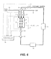
- FIG. 6 shows the construction of the fuel cell system of the third embodiment. This is essentially identical to the construction of the first embodiment, however temperature sensors 31 , 32 are formed in the cooling water passage 9 near the inlet and outlet of the fuel cell stack 1 , respectively. Also, the startup processing of the system performed by the controller 16 is also different.
- the controller 16 calculates a temperature difference ⁇ T of the cooling water between the fuel cell inlet and outlet. From this temperature difference ⁇ T, the reaction status inside the fuel cell stack 1 can be grasped, water clogging can be estimated and cooling water pressure control performed.
- the temperature difference ⁇ T can be measured by installing temperature sensors 31 , 32 at the fuel cell inlet and outlet, respectively, as shown in FIG. 6, or by installing a thermocouple in the cooling water passage 9 . In both cases, temperature measurement can be performed more easily than by measuring the internal temperature of the fuel cell stack 1 by installing sensors inside the fuel cell stack 1 .
- FIG. 7 is a flowchart showing startup processing of the fuel cell system, and is performed at a predetermined time, for example every 10 milliseconds, by the controller 16 .
- step S 31 introduction of fuel gas, air and cooling water to the fuel cell stack 1 is started.
- a step S 32 the cooling water temperatures Tin, Tout at the inlet and outlet of the fuel cell stack 1 are measured.
- step S 33 the temperature difference ⁇ T of cooling water between the inlet and outlet of the fuel cell stack 1 is computed.
- this temperature difference ⁇ T and a preset temperature difference ⁇ Tth are compared. For example, if the outside atmospheric temperature is approximately 20° C. and the running temperature of the fuel cell stack 1 is approximately 60° C.-70° C., the temperature difference ⁇ Tth is set to a value between 20° C.-50° C. When the temperature difference ⁇ T is smaller than ⁇ Tth, it is determined that warmup of the fuel cell stack 1 is not complete and water clogging due to condensation of water may occur in the fuel cell stack 1 , so the routine proceeds to a step S 35 , and the cooling water pressure Pcw is set to Plow ( ⁇ Pnormal).
- the warmup state of the fuel cell stack 1 was determined here based on temperature difference ⁇ T of cooling water at the inlet and outlet of the fuel cell stack 1
- the warmup state of the fuel cell stack 1 may be determined based on the temperature difference of fuel gas or air at the inlet and outlet of the fuel cell stack 1 .
- the sensor at the inlet may be omitted, and the warmup state of the fuel cell stack 1 may be determined from the temperature rise of fluid (cooling water, fuel gas, or air) at the outlet. For example, if it is determined that warmup of the fuel cell stack 1 is complete when the temperature of cooling water at the outlet has risen to a predetermined temperature, the system construction is simplified and control is also simplified.
- fluid cooling water, fuel gas, or air
- the humidification state of the membrane electrode of the fuel cell stack 1 may be detected from the electromotive force etc., as in the preceding embodiment, and if the humidification of the membrane electrode is not sufficient, the cooling water pressure is raised to Plow2 which is higher than the pressure Plow set in the step S 35 , movement of water into the cooling water passage 9 from the cathode 2 and anode 3 is suppressed, and humidification of the membrane electrode is assisted.
- This invention may be applied to various fuel cell systems including those of vehicles, and is useful for preventing water clogging when starting from a low temperature state, and enhancing startup of the fuel cell system.
Landscapes
- Life Sciences & Earth Sciences (AREA)
- Engineering & Computer Science (AREA)
- Manufacturing & Machinery (AREA)
- Sustainable Development (AREA)
- Sustainable Energy (AREA)
- Chemical & Material Sciences (AREA)
- Chemical Kinetics & Catalysis (AREA)
- Electrochemistry (AREA)
- General Chemical & Material Sciences (AREA)
- Fuel Cell (AREA)
Abstract
Before warmup of a fuel cell stack (1) is complete, a cooling water pressure of the fuel cell stack (1) is suppressed lower than the pressure used when the fuel cell system is run in the steady state. In this way, when the system is started from a low temperature state, water in a cathode (2) and anode (3) flows efficiently into the cooling water passage (9), and water clogging is prevented while maintaining a proper water balance in the fuel cell system.
Description
- This invention relates to a fuel cell system, and more particularly to startup control when a fuel cell system is started from a low temperature state.
- A fuel cell system transforms the energy of fuel, directly into electrical energy. In the fuel cell system disclosed by JP8-106914A published by the Japanese Patent Office in 1996, in a pair of electrodes provided on either side of a membrane electrode, fuel gas containing hydrogen is supplied to the anode and an oxidizing agent gas containing oxygen is supplied to the cathode. Electrical energy is then extracted from the electrodes, using the electrochemical reactions produced on the surface of the membrane electrode, i.e.,
- anode reaction: H2→2H++2e −
- cathode reaction: 2H++2e −+(½)O2→H2O
- The fuel gas supplied to the anode, may be supplied directly from a hydrogen storage device, or fuel containing hydrogen may be reformed, and the reformed hydrogen-containing gas supplied to the anode. The fuel containing hydrogen may be natural gas, methanol or gasoline, and the oxidizing agent gas supplied to the cathode is generally air.
- As it is necessary to keep the humidification state of the membrane electrode optimal in order to extract the performance of the membrane electrode in the fuel cell and enhance the power generation efficiency, the fuel gas and air introduced into the fuel cell is humidified. When reforming fuel gas and extracting hydrogen as mentioned above, water is used for reforming. Therefore, in order to use the fuel cell for vehicles, a water balance must be maintained within the fuel cell system including the fuel cell or reforming device. This is because the practicality of a fuel cell vehicle will fall remarkably if water runs short and it becomes necessary to supply pure water periodically.
- There are two means of supplying water to the membrane electrode. One is the method of humidifying the fuel gas or air with a humidifier, and humidifying the membrane electrode using the moisture. Another is the method of connecting a cooling water passage to the anode and cathode in the fuel cell via a bipolar plate comprising a porous material, and supplying water to the membrane electrode from the cooling water to humidify the membrane electrode. Since the latter method does not need a humidifier for fuel gas and air, there is an advantage in that the system construction is simpler.
- When starting the fuel cell system at low temperature, the water generated inside the fuel cell and the moisture in the fuel and air condense inside the fuel cell, and may block the fuel and air passage, which is called “water clogging.” Water clogging reduces the efficiency of the fuel cell, and in particular, water clogging which occurs during startup lengthens the warm-up time of the fuel cell. As the frequency of startup operations is high in vehicles, the lengthening of the warm-up time of the fuel cell system reduces the usability of the fuel cell vehicle.
- One of the methods of resolving water clogging is the blowing away of the condensed water by increasing the pressure of the fuel gas or air. However, if gas or air is delivered to the fuel cell at higher than ordinary operating pressure, the membrane electrode inside the fuel cell or the durability of the sealing will be degraded, the performance of the fuel cell will be reduced and its life will be shortened. In the fuel cell for vehicles, although there are differences in the frequency of use, startup operations may be performed from hundreds of times to thousands of times, so the above decline of performance is remarkable. Also, the ability to vary the pressure of fuel gas and air makes the system construction complicated.
- Another method is to heat the fuel cell stack itself. However, the heating of the fuel cell stack makes the system complex. If the energy required for heating becomes large, the fuel economy of the vehicle decreases. Further, the time required for heating is too long for the vehicle.
- It is therefore an object of this invention to provide a fuel cell stack wherein a cooling water passage is connected to a fuel gas passage and air passage via a porous plate, wherein the water in the anode and cathode flow out efficiently to the cooling water passage during startup from low temperature, the water balance in the fuel cell stack is maintained, and the problem of clogging is resolved.
- In order to achieve above object, this invention provides a fuel cell system, comprising a fuel cell stack wherein a cooling water passage and an electrode are connected via a porous plate through which water can pass, a pressure adjusting device which adjusts the pressure of cooling water in the cooling water passage, and a controller. The controller functions to determine whether warmup of the fuel cell stack is complete based on the running state of the fuel cell stack, and before warmup of the fuel cell stack is complete, control the pressure adjusting device to decrease the cooling water pressure lower than the cooling water pressure after warmup is complete.
- According to an aspect of this invention, this invention provides a startup method for a fuel cell system including a fuel cell stack wherein a cooling water passage and an electrode are connected via a porous plate through which water can pass and a pressure adjusting device which adjusts the pressure of cooling water in the cooling water passage, the method comprising determining whether warmup of the fuel cell stack is complete based on the running state of the fuel cell stack, and before warmup of the fuel cell stack is complete, controlling the pressure adjusting device to decrease the cooling water pressure lower than the cooling water pressure after warmup is complete.
- The details as well as other features and advantages of this invention are set forth in the remainder of the specification and are shown in the accompanying drawings.
- FIG. 1 is a block diagram of a fuel cell system relating to this invention.
- FIG. 2 is a flowchart showing the startup processing of the fuel cell system.
- FIG. 3 is a flowchart showing the startup processing taking the humidification state of a membrane electrode into consideration.
- FIG. 4 is similar to FIG. 1, but is a block diagram of a fuel cell system according to the second embodiment.
- FIG. 5 is a flowchart showing the startup processing according to the second embodiment.
- FIG. 6 is similar to FIG. 1, but is a block diagram of a fuel cell system according to the third embodiment.
- FIG. 7 is a flowchart showing the startup processing according to the third embodiment.
- Referring to FIG. 1 of the drawings, a fuel cell system relating to this invention is provided with a
fuel cell stack 1 comprising plural cells c1, c2, . . . , cn,pressure sensors cooling water pump 12, acooling water tank 13, aheat exchanger 14 and acontroller 16. Atemperature sensor 15 for measuring the internal temperature Tsin of thefuel cell stack 1 is installed inside thefuel cell stack 1. Measurement signals from these sensors are input into thecontroller 16. -
Pressure sensors air passage 8 which supplies air, acooling water passage 9 which supplies cooling water and afuel gas passage 10 which supplies fuel gas to thefuel cell stack 1, in the vicinity of the inlet to thefuel cell stack 1. - The
controller 16 comprises one, two or more microprocessors, a memory and an input/output interface. Thecontroller 16 calculates a pressure difference ΔP between thecooling water passage 9 and electrodes, acathode 2 andanode 3 at the inlet of thefuel cell stack 1, from the signals from thepressure sensors controller 16 determines a pressure Pcw of cooling water according to the internal temperature Tsin of thefuel cell stack 1 detected by thetemperature sensor 15, and controls the opening of apressure reducing valve 11 and the rotation speed of thecooling water pump 12 so that a determined cooling water pressure Pcw is realized. - Specifically, before warm-up of the
fuel cell stack 1 is complete, when the internal temperature Tsin of thefuel cell stack 1 is low and when water clogging by water condensed in thecathode 2 andanode 3 may occur, the pressure Pcw of cooling water is controlled to be lower than the pressure Pnormal used in the steady state after warmup is complete. In this way, the water condensed in thecathode 2 andanode 3 can be made to flow into thecooling water passage 9 efficiently using the pressure difference via the holes in theporous plate 4, and water clogging can be prevented. The cooling performance of thefuel cell stack 1 falls due to the lowering of the cooling water pressure Pcw. However, as this happens before warmup of thefuel cell stack 1 is completed, this does not pose a problem. Conversely, cooling of thefuel cell stack 1 can be suppressed and warmup can be promoted. As water does not flow out to the outside of the system from theair passage 8 and thefuel gas passage 10, the total amount of the water in thefuel cell stack 1 is kept constant, i.e., the water balance is maintained. - Subsequently, if the internal temperature Tsin of the
fuel cell stack 1 rises and warmup is completed, water clogging cannot occur, so the pressure Pcw of cooling water is controlled to the pressure Pnormal in the steady state, and the cooling performance of thefuel cell stack 1 is ensured. - FIG. 2 is a flowchart showing startup processing, and this is performed at a predetermined time, for example every 10 milliseconds, by the
controller 16. - First, in a step S 11, fuel gas, air and cooling water start to be introduced to the
fuel cell stack 1. - In a step S 12, the internal temperature Tsin of the
fuel cell stack 1 is measured. In a step S13, the measured internal temperature Tsin and the predetermined temperature Tth are compared. The predetermined temperature Tth is set according to the shape of the gas, air and cooling water passages, and the construction of the system. For example, it is set to the lowest temperature of the temperatures at which water clogging by the water condensed in thecathode 2 andanode 3 of thefuel cell stack 1 does not occur. The predetermined temperature Tth is set lower than the running temperature (about 60° C.-70° C.) of thefuel cell stack 1. From experiment, it was found that water clogging does not occur above 40° C., and it was possible to run the vehicle by setting the cooling water pressure Pcw to the pressure Pnormal, so the predetermined temperature Tth was set to 40° C. - It was determined that when the internal temperature Tsin is lower than the predetermined temperature Tth, water clogging occurs due to the water condensed in the
cathode 2 andanode 3, so the routine proceeds to step S14, the water pressure Pcw is controlled to a predetermined low pressure power Plow, and the water condensed in thecathode 2 andanode 3 is made to flow out to the coolingwater passage 9. - In order to increase the outflow efficiency of the condensed water, it is preferred to make the cooling water pressure Pcw as low as possible relative to the
cathode 2 andanode 3. However, if the differential pressure ΔP between the coolingwater passage 9 and theelectrodes 2, 3 (cathode 2 and anode 3) becomes too large, fuel gas or oxidizing agent gas penetrates the coolingwater passage 9. If the differential pressure ΔP is further increased, the internal structure of the membrane electrode or cell may break down. Thus, although the cooling water pressure Pcw is controlled to be as low as possible, the differential pressure ΔP between the coolingwater passage 9 and theelectrodes water passage 9. - While the internal temperature Tsin of the
fuel cell stack 1 is lower than the predetermined temperature Tth, the steps S12, S13, S14 are repeated. Subsequently, if warmup of thefuel cell stack 1 proceeds and the internal temperature Tsin exceeds the predetermined temperature Tth, it is determined that the condensation amount of the water in thefuel cell stack 1 is sufficiently small, water clogging by the condensed water does not occur, and the routine proceeds to a step S15. - When the routine proceeds to the step S 15, the cooling water pressure Pcw is controlled to the pressure Pnormal normally used in steady running. Thereafter, the cooling water pressure Pcw is controlled to this ordinary pressure Pnormal, and the cooling performance of the
fuel cell stack 1 is ensured. - Here, the differential pressure ΔP between the cooling
water passage 9 and theelectrodes 2, 3 (cathode 2 and anode 3) is calculated, and the minimum of the cooling water pressure Pcw is set based thereon. However, the pressure value for low cooling water pressure operation (fixed value) may be predefined, and the cooling water pressure Pcw changed over to this preset value immediately in the step S14 when low cooling water pressure running is performed. Thus, the system construction can be simplified and the control response can be improved. - As water may freeze when the internal temperature Tsin of the
fuel cell stack 1 is lower than 0° C., when the detected internal temperature Tsin is lower than 0° C., a routine not shown is performed, and the internal water must be thawed by heating with a heater or circulating high temperature gas to the passage in thefuel cell stack 1 beforehand, and the aforesaid processing performed afterwards. - Moreover, as it is necessary to appropriately humidify the membrane electrode of the
fuel cell stack 1, the humidification state of the membrane electrode is detected, and when the water content of the membrane electrode is smaller than a predetermined value, the pressure Pcw of the coolingwater passage 9 is controlled to a second low pressure Plow2(Plow<Plow2<Pnormal) which is lower than the normal running pressure Pnormal and higher than the pressure Plow set in the step S14. By adding such processing, even the movement of the moisture in the membrane electrode to the coolingwater passage 9 can be prevented, and the humidification state of the membrane electrode can be maintained at a satisfactory level. - FIG. 3 is a flowchart showing the startup processing when taking the humidification state of the membrane electrode into consideration. Steps S 16-S18 are added to what was shown in FIG. 2.
- The humidification state of the membrane electrode is detected in the step S 16. The humidification state of the membrane electrode can be predicted from the state change of the
fuel cell stack 1 such as the change of electromotive force and the reserved water amount in thewater tank 13. More specifically, to predict this more directly, the temperature is detected for every cell forming thefuel cell stack 1, the temperature distribution of cells is measured as shown in the embodiment described below, and the prediction is based thereon. - When it is determined in the step S 17 that humidification of the membrane electrode is not sufficient, the routine proceeds to the step S18, and the pressure Pcw of the cooling
water passage 9 is controlled to the pressure Plow2 which is lower than the normal running pressure Pnormal and higher than the pressure set in the step S14. - Next, a second embodiment of this invention will be described.
- FIG. 4 shows the construction of a fuel cell system of the second embodiment. Temperature sensors 21 are installed which measure the temperatures in each cell c1, c2, . . . , cn of the
fuel cell stack 1, which is a difference from the first embodiment. For convenience, only three sensors 21 have been shown in FIG. 3, but there may be a larger or smaller number of the sensors 21 according to the number of the cells. - Moreover, the startup processings of the system performed by the
controller 16 is also different. Thecontroller 16 predicts water clogging from the temperature distribution of the cells, and performs pressure control of cooling water. The average of the cell temperatures is calculated, and the cooling water pressure Pcw is also controlled based on the differential pressure ΔP between the cooling water and theelectrodes 2, 3 (cathode 2 and anode 3) at the inlet of the fuel cell stack, and the average Tcelave of cell temperature. - Specifically, the
controller 16 predicts water clogging from the dispersion (bias) in the distribution of the cell temperatures. For example, there is a bias in a temperature distribution such as when the temperature of some cells is low and the possibility of water clogging is predicted, the pressure Pcw of cooling water is immediately reduced to the minimum valve Plow of pressure at which penetration of fuel gas or oxidizing agent gas into the coolingwater passage 9 does not take place, and the outflow efficiency of water from thecathode 2 andanode 3 to the coolingwater passage 9 is increased to the maximum so as to rapidly eliminate any water clogging. - Even after water clogging has been resolved, before warmup of the
fuel cell stack 1 is complete, when the average temperature Tcelave of the cell is lower than the predetermined temperature Tth and there is a possibility that water clogging may occur in thefuel cell stack 1, the pressure Pcw of cooling water is controlled lower than the pressure Pnormal in steady running as in the preceding embodiment, and water in thecathode 2 andanode 3 is made to flow efficiently into the coolingwater passage 9 via the holes in theporous plate 4. - FIG. 5 is a flowchart showing startup processing of the fuel cell system, and is performed at a predetermined time, for example every 10 milliseconds, by the
controller 16. - First, in a step S 21, introduction of fuel gas, air and cooling water to the
fuel cell stack 1 is started. In a step S22, the temperatures Tcel1, Tcel2, . . . , Tceln of the cells c1, c2, . . . , cn of thefuel cell stack 1, are measured. - In a step S 23, water clogging is predicted from the distribution of cell temperature. When the temperature of only some cells is lower than the temperature of other cells, it is predicted that water clogging may occur in the cells at low temperature. When it is predicted that there is water clogging, the routine proceeds to a step S24, and the cooling water pressure Pcw is set to the minimum pressure Plow. The minimum pressure Plow is the minimum value of pressure at which penetration of fuel gas or oxidizing agent gas into the cooling
water passage 9 does not take place, and is set based on the differential pressure ΔP between the coolingwater passage 9 and theelectrodes cathode 2 andanode 3 to the coolingwater passage 9 is enhanced to the maximum, and water clogging can be eliminated at an early stage. - When it is determined that the bias of temperature distribution has disappeared and water clogging in the
fuel cell stack 1 was eliminated, the routine proceeds to a step S25 and the average temperature Tcelave of the cells is calculated. - In a step S 26, the average temperature Tcelave of the cells is compared with the predetermined temperature Tth (the minimum temperature of the temperatures at which water clogging due to the condensed water does not occur), and when the cell average temperature Tcelave is lower than the predetermined temperature Tth, the routine proceeds to a step S27, and the cooling water pressure Pcw is set lower than the pressure for steady running, Pnormal, as in the step S14 of the preceding embodiment. When the cell average temperature Tcelave subsequently reaches the predetermined temperature Tth, the routine proceeds to a step S28, and the cooling water pressure Pcw is set to the pressure used for steady running, Pnormal.
- In this embodiment, the cell temperature is measured, and the presence or absence of water clogging is determined from the temperature distribution. When it is determined that there is water clogging, the cooling water pressure Pcw is lowered to the minimum pressure Plow, and priority is given to the outflow of water from the
cathode 2 andanode 3 into the coolingwater passage 9. Thereby, water clogging in thefuel cell stack 1 can be eliminated at an early stage. After water clogging is eliminated, the same startup processing can be performed as in the preceding embodiment according to the cell average temperature Tcelave, and thereafter, the fuel cell system can be started without water clogging. - Also in this embodiment, as in the first embodiment, the humidification state of the membrane electrode of the
fuel cell stack 1 is predicted from the electromotive force etc., and if the humidification of the membrane electrode is not sufficient, the cooling water pressure Pcw is raised to Plow2 which is higher than the pressure Plow set in the step S27, movement of water into the coolingwater passage 9 from thecathode 2 andanode 3 is suppressed, and humidification of the membrane electrode is assisted as in the first embodiment. In particular, in this embodiment, as the cell temperature distribution is detected, the humidification state of the membrane electrode can be predicted with high precision from the change of cell temperature distribution and electromotive force. - Next, a third embodiment of this invention will be described.
- FIG. 6 shows the construction of the fuel cell system of the third embodiment. This is essentially identical to the construction of the first embodiment, however
temperature sensors water passage 9 near the inlet and outlet of thefuel cell stack 1, respectively. Also, the startup processing of the system performed by thecontroller 16 is also different. - The
controller 16 calculates a temperature difference ΔT of the cooling water between the fuel cell inlet and outlet. From this temperature difference ΔT, the reaction status inside thefuel cell stack 1 can be grasped, water clogging can be estimated and cooling water pressure control performed. The temperature difference ΔT can be measured by installingtemperature sensors water passage 9. In both cases, temperature measurement can be performed more easily than by measuring the internal temperature of thefuel cell stack 1 by installing sensors inside thefuel cell stack 1. - FIG. 7 is a flowchart showing startup processing of the fuel cell system, and is performed at a predetermined time, for example every 10 milliseconds, by the
controller 16. - First, in a step S 31, introduction of fuel gas, air and cooling water to the
fuel cell stack 1 is started. - In a step S 32, the cooling water temperatures Tin, Tout at the inlet and outlet of the
fuel cell stack 1 are measured. In a step S33, the temperature difference ΔT of cooling water between the inlet and outlet of thefuel cell stack 1 is computed. - In a step S 34, this temperature difference ΔT and a preset temperature difference ΔTth are compared. For example, if the outside atmospheric temperature is approximately 20° C. and the running temperature of the
fuel cell stack 1 is approximately 60° C.-70° C., the temperature difference ΔTth is set to a value between 20° C.-50° C. When the temperature difference ΔT is smaller than ΔTth, it is determined that warmup of thefuel cell stack 1 is not complete and water clogging due to condensation of water may occur in thefuel cell stack 1, so the routine proceeds to a step S35, and the cooling water pressure Pcw is set to Plow (<Pnormal). - Subsequently, if warmup of the
fuel cell stack 1 continues and the temperature difference ΔT becomes larger than ΔTth, it is assumed that warmup of thefuel cell stack 1 is complete, and the routine proceeds to a step S36. Thereafter, the cooling water pressure Pcw is controlled to the pressure Pnormal normally used for steady running. - Even if warmup completion of the
fuel cell stack 1 is determined based on the temperature difference ΔT of cooling water at the inlet and outlet of thefuel cell stack 1, the same startup processing as in the preceding embodiment is possible. - Although the warmup state of the
fuel cell stack 1 was determined here based on temperature difference ΔT of cooling water at the inlet and outlet of thefuel cell stack 1, the warmup state of thefuel cell stack 1 may be determined based on the temperature difference of fuel gas or air at the inlet and outlet of thefuel cell stack 1. - Further, the sensor at the inlet may be omitted, and the warmup state of the
fuel cell stack 1 may be determined from the temperature rise of fluid (cooling water, fuel gas, or air) at the outlet. For example, if it is determined that warmup of thefuel cell stack 1 is complete when the temperature of cooling water at the outlet has risen to a predetermined temperature, the system construction is simplified and control is also simplified. - Moreover, also in this embodiment, the humidification state of the membrane electrode of the
fuel cell stack 1 may be detected from the electromotive force etc., as in the preceding embodiment, and if the humidification of the membrane electrode is not sufficient, the cooling water pressure is raised to Plow2 which is higher than the pressure Plow set in the step S35, movement of water into the coolingwater passage 9 from thecathode 2 andanode 3 is suppressed, and humidification of the membrane electrode is assisted. - The entire contents of Japanese Patent Application P2001-342937 (filed Nov. 8, 2001) are incorporated herein by reference.
- Although the invention has been described above by reference to a certain embodiment of the invention, the invention is not limited to the embodiment described above. Modifications and variations of the embodiments described above will occur to those skilled in the art, in the light of the above teachings. The scope of the invention is defined with reference to the following claims.
- Industrial Field of Application
- This invention may be applied to various fuel cell systems including those of vehicles, and is useful for preventing water clogging when starting from a low temperature state, and enhancing startup of the fuel cell system.
Claims (13)
1. A fuel cell system, comprising:
a fuel cell stack (1) wherein a cooling water passage (9) and an electrode (2,3) are connected via a porous plate (4) through which water can pass,
a pressure adjusting device (11, 12) which adjusts the pressure of cooling water in the cooling water passage (9), and
a controller (16) which functions to:
determine whether warmup of the fuel cell stack (1) is complete based on the running state of the fuel cell stack (1), and
before warmup of the fuel cell stack (1) is complete, control the pressure adjusting device (11, 12) to decrease the cooling water pressure lower than the cooling water pressure after warmup is complete.
2. The fuel cell system as defined in claim 1 , wherein:
the controller (16) further functions, before warmup of the fuel cell stack (1) is complete, to control the pressure adjusting device (11, 12) to set the cooling water pressure to a pressure at which gas at the electrode (2, 3) does not penetrate the cooling water passage (9).
3. The fuel cell system as defined in claim 1 , wherein:
the controller (16) further functions, before warmup of the fuel cell stack (1) is complete, to control the pressure adjusting device (11, 12) to set the cooling water pressure higher than a minimum value at which gas at the electrode (2, 3) does not penetrate the cooling water passage (9).
4. The fuel cell system as defined in claim 3 , further comprising a sensor (5, 6, 7) which detects a differential pressure between the cooling water passage (9) and the electrode (2, 3) at the inlet of the fuel cell stack (1), and
the controller (16) further functions to determine the minimum value of the pressure at which gas at the electrode (2, 3) does not penetrate the cooling water passage (9) according to the measured differential pressure.
5. The fuel cell system as defined in claim 1 further comprising a sensor (15) which detects the temperature of the fuel cell stack (1), and
the controller (16) further functions to determine that warmup of the fuel cell stack (1) is complete when the temperature of the fuel cell stack (1) has risen to a predetermined temperature.
6. The fuel cell system as defined in claim 5 , wherein:
the sensor (15) which detects the temperature of the fuel cell stack (1) detects the internal temperature of the fuel cell stack (1), and
the controller (16) further functions to determine that warmup of the fuel cell stack (1) is complete when the internal temperature of the fuel cell stack (1) has risen to a predetermined temperature at which water clogging in the fuel cell stack (1) does not occur.
7. The fuel cell system as defined in claim 1 , wherein:
the fuel cell stack (1) includes plural cells (c1, c2, . . . , cn),
the system further comprises sensors (21) which detect the temperatures of the cells (c1, c2, . . . , cn), and
the controller (16) further functions to determine that warmup of the fuel cell stack (1) is complete when the average temperature of the cells (c1, c2, . . . , cn) has risen to a predetermined temperature at which water clogging in the fuel cell stack (1) does not occur.
8. The fuel cell system as defined in claim 7 , wherein:
the controller (16) further functions to predict water clogging in the fuel cell stack (1) from the cell temperature distribution, and controls the pressure of the cooling water to be higher than a minimum value at which gas at the electrode (2, 3) does not penetrate the cooling water passage (9).
9. The fuel cell system as defined in claim 1 , further comprising a sensor (32) which detects the temperature of the fluid supplied to the fuel cell stack (1) at the outlet of the fuel cell stack (1), and
the controller (16) further functions to determine that warmup of the fuel cell stack (1) is complete when the temperature of the fluid at the outlet of the fuel cell stack (1) has risen to a predetermined temperature.
10. The fuel cell system as defined in claim 1 , further comprising a sensor (31, 32) which detects a temperature difference of the fluid supplied to the fuel cell stack (1) at the inlet and outlet of the fuel cell stack (1), wherein:
the controller (16) further functions to determine that warmup of the fuel cell stack (1) is complete when the temperature difference of the fluid at the inlet and outlet of the fuel cell stack (1) has increased to a predetermined temperature.
11. The fuel cell system as defined in claim 9 or 10, wherein the fluid is one of cooling water, fuel gas and air supplied to the fuel cell stack (1).
12. The fuel cell system as defined in claim 1 , wherein the controller (16) further functions to:
determine the humidification state of the membrane electrode of the fuel cell stack (1) from the running state of the fuel cell stack (1), and
when the membrane electrode is not sufficiently humidified, the pressure of the cooling water is increased to suppress outflow of water from the electrode (2,3) to the cooling water passage (9).
13. A startup method for a fuel cell system including a fuel cell stack (1) wherein a cooling water passage (9) and an electrode (2,3) are connected via a porous plate (4) through which water can pass and a pressure adjusting device (11, 12) which adjusts the pressure of cooling water in the cooling water passage (9), the method comprising:
determining whether warmup of the fuel cell stack (1) is complete based on the running state of the fuel cell stack (1), and
before warmup of the fuel cell stack (1) is complete, controlling the pressure adjusting device (11, 12) to decrease the cooling water pressure lower than the cooling water pressure after warmup is complete.
Applications Claiming Priority (3)
| Application Number | Priority Date | Filing Date | Title |
|---|---|---|---|
| JP2001342937A JP3840956B2 (en) | 2001-11-08 | 2001-11-08 | Fuel cell system |
| JP2001-342937 | 2001-11-08 | ||
| PCT/JP2002/010740 WO2003041201A2 (en) | 2001-11-08 | 2002-10-16 | Fuel cell system and its startup control |
Publications (2)
| Publication Number | Publication Date |
|---|---|
| US20030190512A1 true US20030190512A1 (en) | 2003-10-09 |
| US7049016B2 US7049016B2 (en) | 2006-05-23 |
Family
ID=36465423
Family Applications (1)
| Application Number | Title | Priority Date | Filing Date |
|---|---|---|---|
| US10/380,432 Expired - Lifetime US7049016B2 (en) | 2001-11-08 | 2002-10-16 | Fuel cell system and its startup control |
Country Status (1)
| Country | Link |
|---|---|
| US (1) | US7049016B2 (en) |
Cited By (9)
| Publication number | Priority date | Publication date | Assignee | Title |
|---|---|---|---|---|
| US20040112568A1 (en) * | 2002-12-12 | 2004-06-17 | Min-Sheng Liu | Enhanced heat transfer device with electrodes |
| US20070128480A1 (en) * | 2005-12-05 | 2007-06-07 | Lg Electronics Inc. | Fuel cell system |
| US20070166577A1 (en) * | 2006-01-16 | 2007-07-19 | Honda Motor Co., Ltd. | Method of actuating fuel cell system and fuel cell system |
| WO2011023781A1 (en) * | 2009-08-27 | 2011-03-03 | Belenos Clean Power Holding Ag | Method for the early detection of liquid water formation in a fuel cell |
| US20140096728A1 (en) * | 2012-09-28 | 2014-04-10 | Hydrogen Injection Technology, Inc. | Anode of supplementary hydrogen fuel system |
| US20190020046A1 (en) * | 2017-07-12 | 2019-01-17 | Toyota Jidosha Kabushiki Kaisha | Fuel cell system |
| CN110729499A (en) * | 2019-10-29 | 2020-01-24 | 卢善喜 | Fuel cell stack with end plate heating |
| US10916789B2 (en) | 2016-03-21 | 2021-02-09 | Hydrolite Ltd | Alkaline exchange membrane fuel cells system having a bi-polar plate |
| CN116581338A (en) * | 2023-07-14 | 2023-08-11 | 深圳市氢蓝时代动力科技有限公司 | Fuel cell system and control method for fuel cell system |
Families Citing this family (4)
| Publication number | Priority date | Publication date | Assignee | Title |
|---|---|---|---|---|
| JP3918658B2 (en) * | 2002-07-02 | 2007-05-23 | 日産自動車株式会社 | Polymer electrolyte fuel cell |
| KR101084078B1 (en) * | 2009-03-20 | 2011-11-16 | 삼성에스디아이 주식회사 | Fuel cell system and its driving method |
| WO2014052928A1 (en) * | 2012-09-28 | 2014-04-03 | Hydrogen Injection Technology, Inc. | Supplementary hydrogen fuel system |
| KR101673360B1 (en) * | 2015-07-09 | 2016-11-07 | 현대자동차 주식회사 | Cooling system and operating method thereof |
Citations (5)
| Publication number | Priority date | Publication date | Assignee | Title |
|---|---|---|---|---|
| US5736269A (en) * | 1992-06-18 | 1998-04-07 | Honda Giken Kogyo Kabushiki Kaisha | Fuel cell stack and method of pressing together the same |
| US6562503B2 (en) * | 2001-08-22 | 2003-05-13 | Utc Fuel Cells, Llc | Freeze tolerant fuel cell power plant |
| US6596426B2 (en) * | 2001-04-05 | 2003-07-22 | Utc Fuel Cells, Llc | Method and apparatus for the operation of a cell stack assembly during subfreezing temperatures |
| US6617068B2 (en) * | 2001-08-27 | 2003-09-09 | Utc Fuel Cells, Llc | Bi-zone water transport plate for a fuel cell |
| US6794073B2 (en) * | 1999-07-22 | 2004-09-21 | International Fuel Cells, Llc | Direct antifreeze cooled fuel cell |
Family Cites Families (4)
| Publication number | Priority date | Publication date | Assignee | Title |
|---|---|---|---|---|
| JPS60241669A (en) | 1984-05-15 | 1985-11-30 | Mitsubishi Electric Corp | Fuel cell controller |
| JPS60241670A (en) | 1984-05-15 | 1985-11-30 | Mitsubishi Electric Corp | Fuel cell controller |
| JPH08106914A (en) | 1994-09-30 | 1996-04-23 | Aisin Aw Co Ltd | Fuel cell generator |
| JP4037448B2 (en) | 1995-05-25 | 2008-01-23 | 本田技研工業株式会社 | Fuel cell |
-
2002
- 2002-10-16 US US10/380,432 patent/US7049016B2/en not_active Expired - Lifetime
Patent Citations (5)
| Publication number | Priority date | Publication date | Assignee | Title |
|---|---|---|---|---|
| US5736269A (en) * | 1992-06-18 | 1998-04-07 | Honda Giken Kogyo Kabushiki Kaisha | Fuel cell stack and method of pressing together the same |
| US6794073B2 (en) * | 1999-07-22 | 2004-09-21 | International Fuel Cells, Llc | Direct antifreeze cooled fuel cell |
| US6596426B2 (en) * | 2001-04-05 | 2003-07-22 | Utc Fuel Cells, Llc | Method and apparatus for the operation of a cell stack assembly during subfreezing temperatures |
| US6562503B2 (en) * | 2001-08-22 | 2003-05-13 | Utc Fuel Cells, Llc | Freeze tolerant fuel cell power plant |
| US6617068B2 (en) * | 2001-08-27 | 2003-09-09 | Utc Fuel Cells, Llc | Bi-zone water transport plate for a fuel cell |
Cited By (13)
| Publication number | Priority date | Publication date | Assignee | Title |
|---|---|---|---|---|
| US7334627B2 (en) * | 2002-12-12 | 2008-02-26 | Industrial Technology Research Institute | Enhanced heat transfer device with electrodes |
| US20040112568A1 (en) * | 2002-12-12 | 2004-06-17 | Min-Sheng Liu | Enhanced heat transfer device with electrodes |
| US20070128480A1 (en) * | 2005-12-05 | 2007-06-07 | Lg Electronics Inc. | Fuel cell system |
| US20070166577A1 (en) * | 2006-01-16 | 2007-07-19 | Honda Motor Co., Ltd. | Method of actuating fuel cell system and fuel cell system |
| US8241803B2 (en) * | 2006-01-16 | 2012-08-14 | Honda Motor Co., Ltd. | Method of actuating fuel cell system and fuel cell system |
| US9219285B2 (en) | 2009-08-27 | 2015-12-22 | Belenos Clean Power Holding Ag | Method for the early detection of liquid water formation in a fuel cell |
| WO2011023781A1 (en) * | 2009-08-27 | 2011-03-03 | Belenos Clean Power Holding Ag | Method for the early detection of liquid water formation in a fuel cell |
| US20140096728A1 (en) * | 2012-09-28 | 2014-04-10 | Hydrogen Injection Technology, Inc. | Anode of supplementary hydrogen fuel system |
| US10916789B2 (en) | 2016-03-21 | 2021-02-09 | Hydrolite Ltd | Alkaline exchange membrane fuel cells system having a bi-polar plate |
| US20190020046A1 (en) * | 2017-07-12 | 2019-01-17 | Toyota Jidosha Kabushiki Kaisha | Fuel cell system |
| US10714774B2 (en) * | 2017-07-12 | 2020-07-14 | Toyota Jidosha Kabushiki Kaisha | Fuel cell system |
| CN110729499A (en) * | 2019-10-29 | 2020-01-24 | 卢善喜 | Fuel cell stack with end plate heating |
| CN116581338A (en) * | 2023-07-14 | 2023-08-11 | 深圳市氢蓝时代动力科技有限公司 | Fuel cell system and control method for fuel cell system |
Also Published As
| Publication number | Publication date |
|---|---|
| US7049016B2 (en) | 2006-05-23 |
Similar Documents
| Publication | Publication Date | Title |
|---|---|---|
| EP1442493B1 (en) | Fuel cell system and its startup control | |
| JP6886914B2 (en) | Fuel cell system and its control method | |
| JP5576902B2 (en) | Fuel cell system and operation method thereof | |
| US8216733B2 (en) | Fuel cell system | |
| US7049016B2 (en) | Fuel cell system and its startup control | |
| US7579097B2 (en) | Fuel cell voltage feedback control system | |
| KR101134475B1 (en) | Method for controlling fuel cell in low temperature | |
| US20080145714A1 (en) | Fuel Cell System and Related Method | |
| EP1168474A2 (en) | Method of operating a phosphoric acid fuel cell | |
| US9059438B2 (en) | Fuel cell system | |
| JP5348882B2 (en) | Fuel cell system | |
| JP5168859B2 (en) | Fuel cell system | |
| KR100967217B1 (en) | Fuel cell system and its operation stop method | |
| JP2005322527A (en) | Fuel cell system | |
| KR20040028680A (en) | Fuel cell system | |
| JP3991047B2 (en) | Humidifier for fuel cell | |
| JP2007305334A (en) | Fuel cell system | |
| JP6028347B2 (en) | Fuel cell system | |
| JP2006339103A (en) | Fuel cell system | |
| KR100786481B1 (en) | Method and Apparatus for Controlling Operation of Direct Methanol Fuel Cell System | |
| JP2007042477A (en) | Fuel cell system | |
| KR100671682B1 (en) | Heat exchanger device and method for liquid fuel type fuel cell system | |
| JP2008004431A (en) | Fuel cell system | |
| JP2006244962A (en) | Fuel cell system | |
| JP2007220527A (en) | Fuel cell system |
Legal Events
| Date | Code | Title | Description |
|---|---|---|---|
| AS | Assignment |
Owner name: NISSAN MOTOR CO., LTD., JAPAN Free format text: ASSIGNMENT OF ASSIGNORS INTEREST;ASSIGNORS:TAKAHASHI, SHINICHI;YOSHIZAWA, KOUDAI;REEL/FRAME:014188/0923;SIGNING DATES FROM 20030224 TO 20030303 |
|
| STCF | Information on status: patent grant |
Free format text: PATENTED CASE |
|
| FPAY | Fee payment |
Year of fee payment: 4 |
|
| FPAY | Fee payment |
Year of fee payment: 8 |
|
| MAFP | Maintenance fee payment |
Free format text: PAYMENT OF MAINTENANCE FEE, 12TH YEAR, LARGE ENTITY (ORIGINAL EVENT CODE: M1553) Year of fee payment: 12 |