US20030190186A1 - Connecting element for mechanically connecting components - Google Patents
Connecting element for mechanically connecting components Download PDFInfo
- Publication number
- US20030190186A1 US20030190186A1 US10/275,604 US27560403A US2003190186A1 US 20030190186 A1 US20030190186 A1 US 20030190186A1 US 27560403 A US27560403 A US 27560403A US 2003190186 A1 US2003190186 A1 US 2003190186A1
- Authority
- US
- United States
- Prior art keywords
- coupling halves
- connection element
- connection
- element according
- line
- Prior art date
- Legal status (The legal status is an assumption and is not a legal conclusion. Google has not performed a legal analysis and makes no representation as to the accuracy of the status listed.)
- Granted
Links
- 230000008878 coupling Effects 0.000 claims abstract description 145
- 238000010168 coupling process Methods 0.000 claims abstract description 145
- 238000005859 coupling reaction Methods 0.000 claims abstract description 145
- 239000007788 liquid Substances 0.000 claims abstract description 8
- 230000007613 environmental effect Effects 0.000 claims abstract description 6
- 238000005304 joining Methods 0.000 claims description 24
- 238000000429 assembly Methods 0.000 claims description 16
- 239000000853 adhesive Substances 0.000 claims description 12
- 230000001070 adhesive effect Effects 0.000 claims description 12
- 230000000903 blocking effect Effects 0.000 claims description 8
- 238000003825 pressing Methods 0.000 claims description 5
- 239000000126 substance Substances 0.000 claims description 2
- 239000012528 membrane Substances 0.000 claims 2
- XLYOFNOQVPJJNP-UHFFFAOYSA-N water Substances O XLYOFNOQVPJJNP-UHFFFAOYSA-N 0.000 description 20
- 238000009434 installation Methods 0.000 description 19
- 238000007789 sealing Methods 0.000 description 8
- 238000009435 building construction Methods 0.000 description 6
- 238000004519 manufacturing process Methods 0.000 description 5
- 238000010276 construction Methods 0.000 description 4
- 239000010408 film Substances 0.000 description 4
- 238000010438 heat treatment Methods 0.000 description 3
- 230000001681 protective effect Effects 0.000 description 3
- 238000004378 air conditioning Methods 0.000 description 2
- 230000005540 biological transmission Effects 0.000 description 2
- 230000007797 corrosion Effects 0.000 description 2
- 238000005260 corrosion Methods 0.000 description 2
- 230000007547 defect Effects 0.000 description 2
- 238000006073 displacement reaction Methods 0.000 description 2
- 230000002045 lasting effect Effects 0.000 description 2
- 230000004308 accommodation Effects 0.000 description 1
- 230000015572 biosynthetic process Effects 0.000 description 1
- 239000002775 capsule Substances 0.000 description 1
- 230000001419 dependent effect Effects 0.000 description 1
- 230000000694 effects Effects 0.000 description 1
- 230000005611 electricity Effects 0.000 description 1
- 238000007667 floating Methods 0.000 description 1
- 238000000034 method Methods 0.000 description 1
- 230000003068 static effect Effects 0.000 description 1
- 239000010409 thin film Substances 0.000 description 1
- 238000009423 ventilation Methods 0.000 description 1
Images


Classifications
-
- F—MECHANICAL ENGINEERING; LIGHTING; HEATING; WEAPONS; BLASTING
- F16—ENGINEERING ELEMENTS AND UNITS; GENERAL MEASURES FOR PRODUCING AND MAINTAINING EFFECTIVE FUNCTIONING OF MACHINES OR INSTALLATIONS; THERMAL INSULATION IN GENERAL
- F16L—PIPES; JOINTS OR FITTINGS FOR PIPES; SUPPORTS FOR PIPES, CABLES OR PROTECTIVE TUBING; MEANS FOR THERMAL INSULATION IN GENERAL
- F16L37/00—Couplings of the quick-acting type
- F16L37/56—Couplings of the quick-acting type for double-walled or multi-channel pipes or pipe assemblies
-
- E—FIXED CONSTRUCTIONS
- E04—BUILDING
- E04B—GENERAL BUILDING CONSTRUCTIONS; WALLS, e.g. PARTITIONS; ROOFS; FLOORS; CEILINGS; INSULATION OR OTHER PROTECTION OF BUILDINGS
- E04B1/00—Constructions in general; Structures which are not restricted either to walls, e.g. partitions, or floors or ceilings or roofs
- E04B1/38—Connections for building structures in general
-
- Y—GENERAL TAGGING OF NEW TECHNOLOGICAL DEVELOPMENTS; GENERAL TAGGING OF CROSS-SECTIONAL TECHNOLOGIES SPANNING OVER SEVERAL SECTIONS OF THE IPC; TECHNICAL SUBJECTS COVERED BY FORMER USPC CROSS-REFERENCE ART COLLECTIONS [XRACs] AND DIGESTS
- Y10—TECHNICAL SUBJECTS COVERED BY FORMER USPC
- Y10T—TECHNICAL SUBJECTS COVERED BY FORMER US CLASSIFICATION
- Y10T403/00—Joints and connections
- Y10T403/57—Distinct end coupler
Definitions
- connection element for connecting building components effectively, especially building components such as, for example, wall, ceiling and floor elements, as are used in prefabricated building construction.
- Prefabricated building construction is understood to mean buildings that are intended to stand for a relatively long time as well as buildings that are used only for a relatively short time such as, for example, buildings for emergency accommodation after an earthquake, for military uses, for trade fair constructions etc..
- Brackets are adequately known from the prior art so that reference is made merely by way of example to the document U.S. Pat. No. 5,284,311.
- the invention relates likewise to a device for effectively connecting sub-assemblies in a very great variety of forms to wall, ceiling and floor surfaces of buildings or frameworks.
- the following list of sub-assemblies is not exhaustive and is intended merely to illustrate the wide range of applications of the invention:
- wall radiators kitchen unit with gas or electric cooker, oven, air-conditioning unit for wall assembly, utility module having a hot water tank, hot water production unit and various additional devices such as, for example, water filters.
- modules having wash-basin, WC or shower cubicle are shown in FIG. 1 .
- the problem of the present invention is accordingly to make effective the installation of building components and sub-assemblies in the construction sector so that even less well qualified workers can carry out complicated installation work quickly and without mistakes.
- a connection element for connecting building components or sub-assemblies mechanically, the connection element having two coupling halves, which can be brought into engagement by a joining movement.
- the coupling halves can be fastened to the building components or sub-assemblies being connected, using fastening means such as, for example, screws or adhesive.
- the coupling halves and the fastening means are so dimensioned that, when forces occurring in use are applied, the mechanically stable state of the connected building components or sub-assemblies is maintained for a long period.
- Inside the coupling halves there are arranged line coupling halves.
- the line coupling halves are used for connecting liquid lines or gas lines or electrical lines or signal lines such as, for example, for telephone or video devices.
- the line coupling halves are connected to the ends of the lines.
- the lines pass through openings to the outside or pass inside the building component or sub-assembly.
- the coupling halves in the in-use connected state are in the form of housings of the line coupling halves.
- the housing comprising the pushed-together coupling halves is so formed that the line coupling halves and the end portions of the lines being connected are protected from damaging operational or environmental influences. Because the operational or environmental influences may be very varied, the person skilled in the art will, on the basis of the technical teaching imparted, have to design the coupling halves so that, with regard to the specific application, they adequately protect the line coupling halves and the end portions of the lines being connected. It may accordingly be necessary, for example under certain operational conditions, to provide a hermetically sealed housing in order to avoid corrosion on the line coupling halves.
- the line coupling halves are, in the connected state, enclosed on all sides and can have seals that, in the connected state, prevent the entry of atmospheric humidity or water.
- seals that, in the connected state, prevent the entry of atmospheric humidity or water.
- a coupling half can, for example, be open to the rear, despite a requirement for sealing, if the coupling half is arranged within a recess in the building component being connected. Covering and sealing to the rear are, in that instance, accomplished by the building component.
- the basic idea of the invention therefore consists in providing mechanical fastening elements that have couplings for energy and signal supply.
- These mechanical fastening elements are used in same manner as the conventional brackets, that is to say they are fastened using fastening means such as, for example, screws, at the locations intended for that purpose on the building components or sub-assemblies being connected.
- the mechanical fastening elements are so constructed that the line couplings for the energy and signal lines are, in the connected state, so encased that they are adequately protected against damaging influences.
- connection element according to the invention can be arranged recessed in grooves or in blind drilled holes.
- connection of the individual supply and signal lines separately, after joining the building elements together, as a result of which expensive installation time is saved. Because skilled workers are no longer required for connection of the supply and signal lines, the functional reliability of the connection locations can be substantially increased.
- the invention is found to be especially advantageous in the case of modern buildings that are controlled by a building management system. Such building management systems require, amongst other things, a large number of sensors, which are connected to electronic control devices, resulting in extensive wiring. When that wiring is already integrated into the walls, ceilings etc. and is connected automatically and without error in the course of installation of the walls, ceilings etc., costs can be reduced and quality increased.
- connection element is so arranged that the direction of the joining movement of the coupling halves is the same as the direction of the joining movement of the line coupling halves, that is to say when pushing together the mechanical coupling halves the line coupling halves are also pushed together in the same direction.
- This embodiment has a simple arrangement.
- connection element is so arranged that the direction of the joining movement of the coupling halves differs from the direction of the joining movement of the line coupling halves, that is to say the directions of the joining movements are not the same.
- This embodiment is advantageous when structural dimensions of the components being connected allow for only restricted space conditions, that not being feasible using an embodiment according to claim 2.
- connection element is so arranged that the line coupling halves are joined together at the same time as the coupling halves, that is to say when the mechanical coupling shells are completely joined together the line coupling halves are also joined together.
- connection element is so arranged that, during connection, first the coupling halves are completely connected and only thereafter are the line coupling halves joined together.
- This embodiment has particular advantages under especially tough installation conditions. For example, the line coupling halves can remain in a protected position until the coupling halves have been completely closed. Connection of the line coupling halves is performed only within a completely protected housing.
- connection element is so arranged that the line coupling halves can be connected singly or together by means of a connection mechanism.
- the connection mechanism has the following features: a slide mechanism for bringing together the line coupling halves.
- a slide mechanism in this context to be a guideway on which or in which the coupling halves can slide on a track. Such guideways or slide arrangements can be found in relevant textbooks of design theory and are therefore not further described.
- a drive mechanism is provided, the subject-matter of claims 7 and 8 comprising two possible embodiments of a drive mechanism.
- the drive mechanism has a spring mechanism, wherein a blocked, biased spring drives the slide mechanism when blocking of the spring is released automatically or manually.
- Automatic release of the blocking can be carried out, for example, as a result of displacement of a pin blocking the spring, which is brought about when the mechanical coupling halves are joined together and, as a result, blocking of the spring is removed.
- the drive mechanism is arranged to be actuated manually.
- the drive mechanism can be actuated using a key, that is to say when the coupling halves are completely connected, a key-like tool is pushed into a recess—in similar manner to a key-hole.
- the slide mechanism is actuated by rotating the tool.
- the line coupling halves can accordingly be joined together, as well as separated again.
- the person skilled in the art will be familiar with a very great variety of arrangements for solving this problem such as, for example, arrangements from the field of locks or simple arrangements having a rack and pinion, wherein the pinion is turned using the tool, resulting in movement of the rack, which is coupled to the slide mechanism.
- the person skilled in the art will likewise also be familiar with hydraulic or pneumatic solutions, wherein a piston coupled to the slide mechanism is displaced as a result of the introduction of liquid or air into a cylinder.
- connection element is so arranged that the coupling halves have grooves located on the inside and projections matched thereto, which engage with one another when the connection element is in the connected state and serve to maintain or improve the mechanical connection properties.
- Arranged inside the grooves and projections engaging with one another are electric contacts.
- connection element is so arranged that inside the coupling halves there are provided flat portions that are in a close positional relationship to one another when the coupling halves are in the connected state.
- contact elements for producing a signal connection.
- the contact elements located opposite one another touch and the contact is closed. Because the currents flowing for the signal connection are only low, the contact elements can be of small dimensions. As a result of this embodiment, the space required for the signal-related line coupling halves can be reduced.
- connection element whose coupling halves have a rectangular plinth portion, in which fastening holes are provided.
- wedge-shaped or conical engaging elements Arranged on the plinth portion are wedge-shaped or cone-shaped recesses matched thereto.
- the plinth portion can be fastened by simple means on a surface, in a recess or in a groove.
- the form of the engaging elements can be freely selected by the person skilled in the art and matched to the relevant requirements without requiring an inventive step.
- connection element wherein at least one engaging element pair is in the form of a pipe coupling that can be pushed together and that forms the connection for a liquid line.
- This embodiment is especially economical because the double function of the engaging element pair saves having a separate pipe coupling.
- connections are produced as follows: A pressure-activatable adhesive is applied in the factory to the joining press surfaces at the connection locations.
- adhesives are known to the person skilled in the art. They comprise, for example, small spherules in which adhesive is embedded. When carrying out joining under pressure, for example when pressing surfaces together, the spherules burst and release the adhesive so that the joining press surfaces are bonded to one another. A very stable connection is produced as a result of this measure.
- the contacts of the electrical connection elements are encapsulated.
- the capsules are in the form of a plug and coupling.
- a thin film Arranged over each of the areas that are pushed together is a thin film that hermetically seals the electric contacts and, as a result, prevents the entry of moisture and, consequently, corrosion.
- the films are broken when the plug and coupling are joined together. However, that occurs only once a hermetic seal has again been produced by the connection of plug and coupling.
- a specific arrangement is described in an exemplary embodiment.
- FIGS. 1 a - d show, in diagrammatic form, a first embodiment of the invention.
- FIGS. 2 a - d show, in diagrammatic form, a second embodiment of the invention.
- FIGS. 3 a - d show, in diagrammatic form, a third embodiment of the invention, having a pressure-actuated lock.
- FIGS. 4 a - c show, in diagrammatic form, a fourth embodiment of the invention, having a pressure-activatable adhesive connection.
- FIGS. 5 a, b show, in diagrammatic form, a fifth embodiment of the invention, having a protective film.
- FIGS. 6 a - d show, in diagrammatic form, a sixth embodiment of the invention, having a frictional/positive locking connection.
- FIGS. 7 a, b show, in diagrammatic form, a seventh embodiment of the invention.
- FIG. 8 shows, in diagrammatic form, an eighth embodiment of the invention.
- FIG. 9 shows, in diagrammatic form, a ninth embodiment of the invention.
- FIG. 10 shows, in diagrammatic form, a tenth embodiment of the invention.
- FIGS. 11 a, b show, in diagrammatic form, an eleventh embodiment of the invention.
- FIG. 12 shows, in diagrammatic form, a twelfth embodiment of the invention.
- FIGS. 13 - 17 show application examples of the invention.
- FIG. 1 shows, in diagrammatic form, a first embodiment of the invention, wherein reference symbols 1 a and 1 b denote wall portions in which there is arranged the line connection, which consists of a large number of plugs 2 a and a large number of couplings 2 b matched thereto.
- the plugs 2 a are held in an assembly holder 3 a and the couplings 2 b are held in an assembly holder 3 b .
- the assembly holders are fastened in corresponding recesses in the wall portions. The recesses are so constructed that the wall portions can be pushed into one another and form a closed wall portion in the pushed-together state.
- FIG. 1 shows, in diagrammatic form, a first embodiment of the invention, wherein reference symbols 1 a and 1 b denote wall portions in which there is arranged the line connection, which consists of a large number of plugs 2 a and a large number of couplings 2 b matched thereto.
- the plugs 2 a are held in an assembly
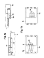
- FIG. 1 a shows, in a side view, two wall portions 1 a and 1 b having recesses, in which assembly holders 3 a and 3 b are fastened by means of screw connections. It will be clear to the person skilled in the art that the fastening of the assembly holders 3 a and 3 b can be accomplished in various ways so that further explanations in this regard can be dispensed with.
- FIG. 1 b shows the invention in a top view, wherein three line plugs 2 a and three line couplings 2 b can be seen. In the present case, sealing between the line plug 2 a and the line coupling 2 b is carried out by means of an O ring 4 .
- FIG. 1 d shows the end state, wherein the three lines are connected to one another reliably and sealed. Additional constructional measures ensure that the two wall portions 1 a and 1 b are held in the position according to FIG. 1 d.
- FIG. 2 shows, in diagrammatic form, a second embodiment of the invention, wherein assembly holders 3 a and 3 b have a centring device 5 a , 5 b , which guarantees reliable joining.
- the centring device is so dimensioned that the transverse forces that occur when the walls are joined together are reliably taken up, so that the coupling halves are not damaged by being brought together in misaligned manner.
- FIG. 2 is analogous to FIG. 1, so that the person skilled in the art will not need it to be described again.
- FIG. 3 shows, in diagrammatic form, a third embodiment of the invention, wherein there is provided a locking device 6 which reliably prevents the building components such as, for example, walls from coming apart again and, consequently, the coupling halves from becoming loose or, as a result, from being damaged in such a way that sealing is no longer ensured.
- the locking device 6 has a pressure piston and cylinder arrangement 6 a and also a locking piston and cylinder arrangement 6 b , which are connected to one another by means of a hydraulic line 6 c .
- FIG. 4 A means of producing a lasting and stable connection is shown in FIG. 4. All contacting surfaces of the centring device are coated with a special adhesive 7 . When the contacting surfaces are pressed together under strong pressure, the adhesive 7 is activated and it fixedly connects the contacting surfaces to one another.
- a pressure-activatable adhesives are known to the person skilled in the art so that a more detailed explanation thereof is not necessary.
- the coupling halves are covered with a protective film 8 according to FIG. 5.
- the protective film 8 is broken in controlled manner so that the hitherto hermetically sealed, that is to say non-corroded, elements of the coupling halves are joined together.
- sealing elements are provided which re-establish a hermetic seal after joining.
- FIG. 6 shows a simple and very effective measure for reliable and lasting connection.
- the contacting surfaces of the centring device are provided with a multi-wedge-shaped surface toothed arrangement 9 .
- the teeth of the surface toothed arrangement 9 lock in and remain in that position so that a positive and frictional connection is produced.
- the multi-toothed arrangement must be asymmetrical so that the hooking-in effect occurs in only one direction, that is to say, in the present example, on pressing together the contacting surfaces.
- FIGS. 1 to 6 show the various embodiments of the invention with reference to a substantially similar basic form of coupling.
- the various installation phases are illustrated so that it is possible, for the person skilled in the art, to dispense with repetitions in the description.
- the following examples show that it is also possible to use basic forms of coupling that are different in principle.
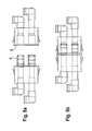
- FIG. 7 shows an embodiment of the coupling having two coupling halves 1 a , 1 b , with only a water pipe 10 being connected in this embodiment.
- the two pipe portions 10 a , 10 b are located one above the other.
- a seal arrangement 11 a , 11 b is provided for the purpose of sealing.
- FIG. 8 shows a coupling half 1 a wherein an angled water pipe 10 is movably arranged.
- the water pipe has, on its surface, a toothed arrangement 12 , which is in engagement with a pinion 13 .
- the water pipe 10 is pressed against the pinion 13 by a counter-mounting 14 .
- the pinion 13 is connected to a pin 15 which is rotatably mounted in a mounting 16 .
- the water pipe can accordingly be displaced in its longitudinal extent.
- the coupling half 1 a is placed on a coupling half matched thereto, the coupling halves of the water pipes to be connected are not yet in engagement. Only as a result of turning the tool 17 and the resulting displacement of the first water pipe towards the water pipe of the other coupling half is the connection accomplished.
- This exemplary embodiment is accordingly a practical form of the invention according to claim 5 and the claims dependent thereon.
- FIG. 9 shows a similar coupling half 1 a to FIG. 8.
- the water pipe 10 is likewise displaceably mounted and is urged in the direction of the arrow by means of a spring 18 .
- the coupling half 1 a is placed on a coupling half matched thereto, the coupling halves of the water pipes to be connected are not yet in engagement because a blocking pin 19 prevents movement of the pipe. Only by pulling out the blocking pin 19 , using a pull rope 20 , is a stop 21 released, as a result of which the pipe moves in the direction of the arrow and is coupled to its counterpart component.
- the sealing arrangements required for the purpose preferably have O rings.
- FIG. 10 shows a coupling half 1 a having an integrally formed water pipe coupling 22 .
- the integral formation saves having a separate coupling element for the water line.
- the water pipe coupling forms a sturdy central element which is also capable of taking up large mechanical forces.
- Reference symbol 23 denotes a spring-loaded blocking flap, shown in diagrammatic form, which on coupling together is pressed in the direction of the arrow by the counterpart component and in the final state snaps into a recess in the counterpart component. As a result, the coupling is effectively prevented from coming apart.
- FIG. 11 a likewise shows a first coupling half 1 a having an integrally formed water pipe coupling 22 .
- electrical contacts 24 are provided inside the engagement grooves for the transmission of electrical energy.
- FIG. 11 b shows the second coupling half matched thereto.
- FIG. 12 shows a further embodiment of the invention.
- the coupling halves are in the form of wedge-shaped profiled rods 27 , 28 , the first coupling half having a male wedge 29 and the second coupling half having a female wedge 30 .
- a positively acting connection device 31 a, b the mode of operation of which can be seen in FIG. 12.
- the connection device 31 a engages around the connection device 31 b .
- the dimensioning of this connection device 31 is not described in further detail because such click-in connection arrangements are adequately known and can be arranged as required.
- line coupling elements 32 to 35 are provided inside the connection device, which are connected to one another when the profiled rods 27 , 28 are coupled together.
- FIG. 13 shows a possible application of the invention in the field of heating and water installation.
- Various units are arranged on a baseplate 36 .
- Arranged in the wall are four couplings 37 , 38 ( 39 , 40 not shown) according to the invention, which are connected to various lines running within the wall.
- Arranged on the baseplate 36 are the counterparts matched to the couplings 37 to 40 .
- the baseplate 36 can be completely or possibly even automatically kitted out at the manufacturer's.
- the kitted-out baseplate is simply hung into place on site. It will be clear that the installation costs on site can be considerably reduced as a result. Furthermore, kitting-out is carried out in a very short time and the risk of mis-connection or incorrect wiring is ruled out.
- FIG. 14 shows a further possible application of the invention in the kitchen sector. It can be seen from the drawing, without more detailed explanation, that a complete kitchen unit consisting of a refrigerator, electric cooker and sink unit together with dishwasher can be hung onto a wall analogously to the description of FIG. 13, reference symbols 41 to 45 denoting the visible couplings.
- FIG. 15 shows a further possible application of the invention in the bathroom sector. It can be seen from the drawing, without more detailed explanation, that a complete sanitary unit block consisting of a shower cubicle, toilet, wash-basin together with a mirrored cabinet can be fastened to a wall with little outlay analogously to the description of FIG. 13, reference symbols 46 to 52 denoting the couplings.
- FIG. 16 shows a further possible application of the invention in the installation of public telephone devices.
- Arranged on the rear of the telephone device are two couplings 53 , 54 according to the invention and a locking device 55 that can be secured.
- the telephone device can accordingly be rapidly exchanged in the event of a defect and is secured against theft by means of the locking device.
- FIG. 17 shows a further possible application of the invention in the heating sector.
- a baseplate 56 fastened to a wall are couplings 57 to 60 , couplings 58 and 59 being constructed in accordance with the invention. It will be clear that, using this arrangement, panel radiators can be installed very quickly or exchanged in the event of a defect.
Landscapes
- Engineering & Computer Science (AREA)
- General Engineering & Computer Science (AREA)
- Architecture (AREA)
- Mechanical Engineering (AREA)
- Physics & Mathematics (AREA)
- Electromagnetism (AREA)
- Civil Engineering (AREA)
- Structural Engineering (AREA)
- Quick-Acting Or Multi-Walled Pipe Joints (AREA)
- Joining Of Building Structures In Genera (AREA)
- Connector Housings Or Holding Contact Members (AREA)
- Connections Effected By Soldering, Adhesion, Or Permanent Deformation (AREA)
- Piezo-Electric Or Mechanical Vibrators, Or Delay Or Filter Circuits (AREA)
- Mutual Connection Of Rods And Tubes (AREA)
- Installation Of Indoor Wiring (AREA)
- Domestic Plumbing Installations (AREA)
- Building Environments (AREA)
- Connection Of Plates (AREA)
- Clamps And Clips (AREA)
- Non-Disconnectible Joints And Screw-Threaded Joints (AREA)
Abstract
The invention relates to a connecting element for efficiently connecting components and subassemblies with the most diverse configurations to wall, ceiling and floor surfaces of buildings or frames. The connecting element has two coupling halves (1 a , 1 b) that can be interconnected by jointing and can be fixed to components or subassemblies to be connected by fixing means. The coupling halves and the fixing means are proportioned to guarantee that the connected components or subassemblies maintain a predetermined mechanically stable state during the exertion of operational forces. According to the invention, coupling halves of conduits (2 a , 2 b , 10, 22, 32, 33, 34, 35) are arranged inside the coupling halves for connecting liquid conduits, gas conduits, electrical conduits or signal conduits, whereby during operation, the conduit coupling halves are connected to the end sections of the conduits to be connected and the coupling halves (1 a , 1 b) have passages, through which the conduits are directed towards the exterior. The coupling halves are configured in the connected operational state as a housing for the conduit coupling halves (2 a , 2 b , 10, 22, 32, 33, 34, 35), said housing being designed in such a way that the conduit coupling halves (2 a , 2 b, 10, 22, 32, 33, 34, 35) and the end sections of the conduits to be connected are protected from operational or environmental damage.
Description
- The invention relates to a connection element for connecting building components effectively, especially building components such as, for example, wall, ceiling and floor elements, as are used in prefabricated building construction. Prefabricated building construction is understood to mean buildings that are intended to stand for a relatively long time as well as buildings that are used only for a relatively short time such as, for example, buildings for emergency accommodation after an earthquake, for military uses, for trade fair constructions etc..
- Various connection arrangements are known in prefabricated building construction for connecting wall, ceiling and floor elements. Frequently, for example, wall elements are push-fitted together and then the push-fit connections are bolted together. So-called brackets, which are screwed to the locations being connected, are increasingly being used in prefabricated building construction. Brackets are adequately known from the prior art so that reference is made merely by way of example to the document U.S. Pat. No. 5,284,311.
- There is, and there will also be in the future, a need to minimise work on site because work on site generally has to be carried out using local workers who may, depending on circumstances, be poorly trained or expensive. Furthermore, there are scarcely any possibilities for automating installation on site, as a result of which reduction of the costs arising on site can be achieved only with difficulty. A further problem is the construction time, which, in the case of laborious manual installation of wall elements, can be shortened only to a limited degree.
- It is accordingly problematic that, in prefabricated building construction, manufacture of the building components can be carried out with a high degree of automation and a high production quality can also be achieved, whereas, during installation of the prefabricated elements on site, the speed of installation and the quality of work can, in contrast, be influenced only to a small extent.
- There is, however, a permanent need to reduce construction costs and to improve the quality of assembled structures, the expression “assembled structures” being understood to mean any structure that is put together on site from prefabricated elements, the necessary work substantially being carried out manually by qualified workers.
- The invention relates likewise to a device for effectively connecting sub-assemblies in a very great variety of forms to wall, ceiling and floor surfaces of buildings or frameworks. The following list of sub-assemblies is not exhaustive and is intended merely to illustrate the wide range of applications of the invention:
- Sub-assemblies from the area of heating, ventilation and air-conditioning:
- wall radiators, kitchen unit with gas or electric cooker, oven, air-conditioning unit for wall assembly, utility module having a hot water tank, hot water production unit and various additional devices such as, for example, water filters.
- Sub-assemblies from the sanitary area:
- modules having wash-basin, WC or shower cubicle.
- In similar manner to the production of prefabricated buildings, there is also the problem, in the case of the sub-assemblies mentioned above, of effective and reliable installation on site, especially in cases where the sub-assemblies have a large number of connection points and connections such as, for example, for water, gas, electricity or/and telephone and data-processing devices. Because the complexity of the sub-assemblies is increasing further, highly qualified skilled workers are required for installation on site. As a result, installation costs are increasing. If qualified staff are not used there is an increase in failures, for example as a result of incorrect electrical or signal connections, the correction of which likewise gives rise to high costs.
- The problem of the present invention is accordingly to make effective the installation of building components and sub-assemblies in the construction sector so that even less well qualified workers can carry out complicated installation work quickly and without mistakes.
- The problem is solved by a device according to claim 1.
- A connection element is provided for connecting building components or sub-assemblies mechanically, the connection element having two coupling halves, which can be brought into engagement by a joining movement. The coupling halves can be fastened to the building components or sub-assemblies being connected, using fastening means such as, for example, screws or adhesive. The coupling halves and the fastening means are so dimensioned that, when forces occurring in use are applied, the mechanically stable state of the connected building components or sub-assemblies is maintained for a long period. Inside the coupling halves there are arranged line coupling halves. The line coupling halves are used for connecting liquid lines or gas lines or electrical lines or signal lines such as, for example, for telephone or video devices. The line coupling halves are connected to the ends of the lines. The lines pass through openings to the outside or pass inside the building component or sub-assembly.
- In accordance with the invention, the coupling halves in the in-use connected state are in the form of housings of the line coupling halves. The housing comprising the pushed-together coupling halves is so formed that the line coupling halves and the end portions of the lines being connected are protected from damaging operational or environmental influences. Because the operational or environmental influences may be very varied, the person skilled in the art will, on the basis of the technical teaching imparted, have to design the coupling halves so that, with regard to the specific application, they adequately protect the line coupling halves and the end portions of the lines being connected. It may accordingly be necessary, for example under certain operational conditions, to provide a hermetically sealed housing in order to avoid corrosion on the line coupling halves. In that case, the line coupling halves are, in the connected state, enclosed on all sides and can have seals that, in the connected state, prevent the entry of atmospheric humidity or water. The very great variety of forms of such seals are adequately known to the person skilled in the art, for example from the field of the installation of electric cables in wet rooms.
- It should be mentioned that the procedure for dimensioning and designing the coupling halves is as follows:
- a. dimensioning according to the mechanical operational forces to be expected, taking into account the installation situation and the space required for the line coupling halves;
- b. dimensioning according to the damaging operational and environmental influences to be expected, the specific installation conditions also having to be taken into account in this instance. Accordingly, a coupling half can, for example, be open to the rear, despite a requirement for sealing, if the coupling half is arranged within a recess in the building component being connected. Covering and sealing to the rear are, in that instance, accomplished by the building component.
- The basic idea of the invention therefore consists in providing mechanical fastening elements that have couplings for energy and signal supply. These mechanical fastening elements are used in same manner as the conventional brackets, that is to say they are fastened using fastening means such as, for example, screws, at the locations intended for that purpose on the building components or sub-assemblies being connected. The mechanical fastening elements are so constructed that the line couplings for the energy and signal lines are, in the connected state, so encased that they are adequately protected against damaging influences.
- The main advantage of the invention is that, for the first time, there is provided a connector that can be used in highly universal manner, that—depending on the requirement—can be used in the same manner as a conventional bracket for a very great variety of purposes and that can be installed with little difficulty at freely selectable locations on the building components or sub-assemblies being connected. As is usual in the case of conventional brackets, the connection element according to the invention can be arranged recessed in grooves or in blind drilled holes.
- It is accordingly no longer necessary to carry out connection of the individual supply and signal lines separately, after joining the building elements together, as a result of which expensive installation time is saved. Because skilled workers are no longer required for connection of the supply and signal lines, the functional reliability of the connection locations can be substantially increased. The invention is found to be especially advantageous in the case of modern buildings that are controlled by a building management system. Such building management systems require, amongst other things, a large number of sensors, which are connected to electronic control devices, resulting in extensive wiring. When that wiring is already integrated into the walls, ceilings etc. and is connected automatically and without error in the course of installation of the walls, ceilings etc., costs can be reduced and quality increased.
- It will be clear to the person skilled in the art that the general inventive idea can be put into practice in a great variety of arrangements. The description of embodiments of the subordinate claims and of exemplary embodiments indicates basic arrangements so that the invention is adequately disclosed to the person skilled in the art.
- According to claim 2, the connection element is so arranged that the direction of the joining movement of the coupling halves is the same as the direction of the joining movement of the line coupling halves, that is to say when pushing together the mechanical coupling halves the line coupling halves are also pushed together in the same direction. This embodiment has a simple arrangement.
- According to claim 3, the connection element is so arranged that the direction of the joining movement of the coupling halves differs from the direction of the joining movement of the line coupling halves, that is to say the directions of the joining movements are not the same. This embodiment is advantageous when structural dimensions of the components being connected allow for only restricted space conditions, that not being feasible using an embodiment according to claim 2.
- According to claim 4, the connection element is so arranged that the line coupling halves are joined together at the same time as the coupling halves, that is to say when the mechanical coupling shells are completely joined together the line coupling halves are also joined together. This embodiment makes possible a simple and economical arrangement.
- According to claim 5, the connection element is so arranged that, during connection, first the coupling halves are completely connected and only thereafter are the line coupling halves joined together. This embodiment has particular advantages under especially tough installation conditions. For example, the line coupling halves can remain in a protected position until the coupling halves have been completely closed. Connection of the line coupling halves is performed only within a completely protected housing.
- According to claim 6, the connection element is so arranged that the line coupling halves can be connected singly or together by means of a connection mechanism. The connection mechanism has the following features: a slide mechanism for bringing together the line coupling halves. The person skilled in the art will understand a slide mechanism in this context to be a guideway on which or in which the coupling halves can slide on a track. Such guideways or slide arrangements can be found in relevant textbooks of design theory and are therefore not further described. In order to drive the slide mechanism, a drive mechanism is provided, the subject-matter of
claims 7 and 8 comprising two possible embodiments of a drive mechanism. - According to
claim 7, the drive mechanism has a spring mechanism, wherein a blocked, biased spring drives the slide mechanism when blocking of the spring is released automatically or manually. Automatic release of the blocking can be carried out, for example, as a result of displacement of a pin blocking the spring, which is brought about when the mechanical coupling halves are joined together and, as a result, blocking of the spring is removed. Such arrangements may either be found complete in relevant textbooks or are part of the technical knowledge that is always at the disposal of a design engineer, who is therefore not required to act inventively. - According to claim 8, the drive mechanism is arranged to be actuated manually. For example, the drive mechanism can be actuated using a key, that is to say when the coupling halves are completely connected, a key-like tool is pushed into a recess—in similar manner to a key-hole. The slide mechanism is actuated by rotating the tool. The line coupling halves can accordingly be joined together, as well as separated again. Here too, the person skilled in the art will be familiar with a very great variety of arrangements for solving this problem such as, for example, arrangements from the field of locks or simple arrangements having a rack and pinion, wherein the pinion is turned using the tool, resulting in movement of the rack, which is coupled to the slide mechanism. The person skilled in the art will likewise also be familiar with hydraulic or pneumatic solutions, wherein a piston coupled to the slide mechanism is displaced as a result of the introduction of liquid or air into a cylinder.
- According to
claim 9, the connection element is so arranged that the coupling halves have grooves located on the inside and projections matched thereto, which engage with one another when the connection element is in the connected state and serve to maintain or improve the mechanical connection properties. Arranged inside the grooves and projections engaging with one another are electric contacts. Using this embodiment, the space required for the electric line coupling halves can be reduced because the electric contacts are integrally connected to the coupling half in question. - According to
claim 10, the connection element is so arranged that inside the coupling halves there are provided flat portions that are in a close positional relationship to one another when the coupling halves are in the connected state. Provided on those flat portions are contact elements for producing a signal connection. When the coupling halves are in the connected state, the contact elements located opposite one another touch and the contact is closed. Because the currents flowing for the signal connection are only low, the contact elements can be of small dimensions. As a result of this embodiment, the space required for the signal-related line coupling halves can be reduced. - According to claim 11, there is provided a connection element whose coupling halves have a rectangular plinth portion, in which fastening holes are provided. Arranged on the plinth portion are wedge-shaped or conical engaging elements and wedge-shaped or cone-shaped recesses matched thereto. The plinth portion can be fastened by simple means on a surface, in a recess or in a groove. The form of the engaging elements can be freely selected by the person skilled in the art and matched to the relevant requirements without requiring an inventive step.
- According to
claim 12, there is provided a connection element wherein at least one engaging element pair is in the form of a pipe coupling that can be pushed together and that forms the connection for a liquid line. This embodiment is especially economical because the double function of the engaging element pair saves having a separate pipe coupling. - According to
claim 13, in the case of the media supply connection elements in pipe form, there is provided a pressure-actuatable internal lock and internal seal which bring about locking and sealing of the connection when it is subjected to pressure by means of liquid or gas. The advantage of this embodiment is that, after all media connection locations have been completely installed, they can be sealed in a single operation by the propagation of pressure. - According to
claim 14, the connections are produced as follows: A pressure-activatable adhesive is applied in the factory to the joining press surfaces at the connection locations. Such adhesives are known to the person skilled in the art. They comprise, for example, small spherules in which adhesive is embedded. When carrying out joining under pressure, for example when pressing surfaces together, the spherules burst and release the adhesive so that the joining press surfaces are bonded to one another. A very stable connection is produced as a result of this measure. - According to
claim 15, there is provided on the joining press surfaces, which are in pressing contact on being joined together, an asymmetrical surface toothed arrangement, which forms a unilaterally acting frictional and positive connection after pressing together. - It is left to the person skilled in the art to select suitable locations for arranging the adhesive connection or the surface toothed arrangement because it is only necessary, for that purpose, to have knowledge of the strength or static characteristics of the specific building construction.
- According to
claim 16, the contacts of the electrical connection elements are encapsulated. The capsules are in the form of a plug and coupling. Arranged over each of the areas that are pushed together is a thin film that hermetically seals the electric contacts and, as a result, prevents the entry of moisture and, consequently, corrosion. The films are broken when the plug and coupling are joined together. However, that occurs only once a hermetic seal has again been produced by the connection of plug and coupling. A specific arrangement is described in an exemplary embodiment. - According to
claim 17, there is introduced into the plug and the coupling a moisture-binding substance which lastingly absorbs environmental moisture that may still enter when the plug and coupling are joined together. - The invention will be described below in greater detail with reference to exemplary embodiments and selected application examples in conjunction with the accompanying diagrammatic drawings.
- FIGS. 1 a-d show, in diagrammatic form, a first embodiment of the invention.
- FIGS. 2 a-d show, in diagrammatic form, a second embodiment of the invention.
- FIGS. 3 a-d show, in diagrammatic form, a third embodiment of the invention, having a pressure-actuated lock.
- FIGS. 4 a-c show, in diagrammatic form, a fourth embodiment of the invention, having a pressure-activatable adhesive connection.
- FIGS. 5 a, b show, in diagrammatic form, a fifth embodiment of the invention, having a protective film.
- FIGS. 6 a-d show, in diagrammatic form, a sixth embodiment of the invention, having a frictional/positive locking connection.
- FIGS. 7 a, b show, in diagrammatic form, a seventh embodiment of the invention.
- FIG. 8 shows, in diagrammatic form, an eighth embodiment of the invention.
- FIG. 9 shows, in diagrammatic form, a ninth embodiment of the invention.
- FIG. 10 shows, in diagrammatic form, a tenth embodiment of the invention.
- FIGS. 11 a, b show, in diagrammatic form, an eleventh embodiment of the invention.
- FIG. 12 shows, in diagrammatic form, a twelfth embodiment of the invention.
- FIGS. 13-17 show application examples of the invention.
- FIG. 1 shows, in diagrammatic form, a first embodiment of the invention, wherein
reference symbols plugs 2 a and a large number ofcouplings 2 b matched thereto. Theplugs 2 a are held in anassembly holder 3 a and thecouplings 2 b are held in anassembly holder 3 b. The assembly holders are fastened in corresponding recesses in the wall portions. The recesses are so constructed that the wall portions can be pushed into one another and form a closed wall portion in the pushed-together state. FIG. 1a shows, in a side view, twowall portions assembly holders assembly holders line couplings 2 b can be seen. In the present case, sealing between theline plug 2 a and theline coupling 2 b is carried out by means of an O ring 4. When the twowall portions line couplings 2 b come into engagement. In order to compensate for manufacturing tolerances, the line plugs 2 a and/or theline couplings 2 b are mounted in floating (i.e. laterally displaceable) manner. This measure guarantees a constraint-free and reliable connection. FIG. 1d shows the end state, wherein the three lines are connected to one another reliably and sealed. Additional constructional measures ensure that the twowall portions - FIG. 2 shows, in diagrammatic form, a second embodiment of the invention, wherein
assembly holders centring device - FIG. 3 shows, in diagrammatic form, a third embodiment of the invention, wherein there is provided a locking device 6 which reliably prevents the building components such as, for example, walls from coming apart again and, consequently, the coupling halves from becoming loose or, as a result, from being damaged in such a way that sealing is no longer ensured. In the present example, the locking device 6 has a pressure piston and
cylinder arrangement 6 a and also a locking piston andcylinder arrangement 6 b, which are connected to one another by means of ahydraulic line 6 c. When the building components and the coupling halves are reliably connected, there is exerted on the pressure piston of the pressure piston andcylinder arrangement 6 a a force that displaces the piston, as a result of which the locking piston of the locking piston andcylinder arrangement 6 b is pressed, by means of thehydraulic line 6 c, into arecess 6 d, as a result of which the building components are firmly and reliably connected to one another. The application of force to the pressure piston can be accomplished, for example, by utilising the force exerted on joining the building components together. In FIG. 3d it can be seen that the locking piston has engaged in therecess 6 d. - A means of producing a lasting and stable connection is shown in FIG. 4. All contacting surfaces of the centring device are coated with a
special adhesive 7. When the contacting surfaces are pressed together under strong pressure, the adhesive 7 is activated and it fixedly connects the contacting surfaces to one another. Such pressure-activatable adhesives are known to the person skilled in the art so that a more detailed explanation thereof is not necessary. - In order to prevent the coupling halves from corroding, which is especially disadvantageous, for example, in the case of electrical connections, the coupling halves are covered with a protective film 8 according to FIG. 5. On joining, the protective film 8 is broken in controlled manner so that the hitherto hermetically sealed, that is to say non-corroded, elements of the coupling halves are joined together. In a further embodiment, sealing elements are provided which re-establish a hermetic seal after joining.
- FIG. 6 shows a simple and very effective measure for reliable and lasting connection. The contacting surfaces of the centring device are provided with a multi-wedge-shaped surface
toothed arrangement 9. When the contacting surfaces are pressed against one another in the course of joining, the teeth of the surfacetoothed arrangement 9 lock in and remain in that position so that a positive and frictional connection is produced. The person skilled in the art will know that, for this purpose, the multi-toothed arrangement must be asymmetrical so that the hooking-in effect occurs in only one direction, that is to say, in the present example, on pressing together the contacting surfaces. - FIGS. 1 to 6 show the various embodiments of the invention with reference to a substantially similar basic form of coupling. The various installation phases are illustrated so that it is possible, for the person skilled in the art, to dispense with repetitions in the description. The following examples show that it is also possible to use basic forms of coupling that are different in principle.
- FIG. 7 shows an embodiment of the coupling having two
coupling halves water pipe 10 being connected in this embodiment. When the coupling halves are pushed together, the twopipe portions seal arrangement - FIG. 8 shows a
coupling half 1 a wherein anangled water pipe 10 is movably arranged. The water pipe has, on its surface, atoothed arrangement 12, which is in engagement with apinion 13. Thewater pipe 10 is pressed against thepinion 13 by a counter-mounting 14. Thepinion 13 is connected to apin 15 which is rotatably mounted in a mounting 16. By means of atool 17, the water pipe can accordingly be displaced in its longitudinal extent. When thecoupling half 1 a is placed on a coupling half matched thereto, the coupling halves of the water pipes to be connected are not yet in engagement. Only as a result of turning thetool 17 and the resulting displacement of the first water pipe towards the water pipe of the other coupling half is the connection accomplished. This exemplary embodiment is accordingly a practical form of the invention according to claim 5 and the claims dependent thereon. - FIG. 9 shows a
similar coupling half 1 a to FIG. 8. Thewater pipe 10 is likewise displaceably mounted and is urged in the direction of the arrow by means of aspring 18. When thecoupling half 1 a is placed on a coupling half matched thereto, the coupling halves of the water pipes to be connected are not yet in engagement because a blockingpin 19 prevents movement of the pipe. Only by pulling out the blockingpin 19, using apull rope 20, is astop 21 released, as a result of which the pipe moves in the direction of the arrow and is coupled to its counterpart component. The sealing arrangements required for the purpose preferably have O rings. - FIG. 10 shows a
coupling half 1 a having an integrally formedwater pipe coupling 22. The integral formation saves having a separate coupling element for the water line. As can be seen from the illustration, the water pipe coupling forms a sturdy central element which is also capable of taking up large mechanical forces.Reference symbol 23 denotes a spring-loaded blocking flap, shown in diagrammatic form, which on coupling together is pressed in the direction of the arrow by the counterpart component and in the final state snaps into a recess in the counterpart component. As a result, the coupling is effectively prevented from coming apart. - FIG. 11 a likewise shows a
first coupling half 1 a having an integrally formedwater pipe coupling 22. In addition,electrical contacts 24 are provided inside the engagement grooves for the transmission of electrical energy. Furthermore, there are arranged on the rectangular plinth element 25 a row ofsmall contact elements 26, which may be used, for example, for the transmission of sensor signals such as, for example, temperature. FIG. 11b shows the second coupling half matched thereto. - FIG. 12 shows a further embodiment of the invention. The coupling halves are in the form of wedge-shaped profiled
rods male wedge 29 and the second coupling half having afemale wedge 30. There is furthermore provided a positively actingconnection device 31 a, b, the mode of operation of which can be seen in FIG. 12. When both profiled rods are brought into engagement, theconnection device 31 a engages around theconnection device 31 b. The dimensioning of this connection device 31 is not described in further detail because such click-in connection arrangements are adequately known and can be arranged as required. Provided inside the connection device areline coupling elements 32 to 35, which are connected to one another when the profiledrods - FIG. 13 shows a possible application of the invention in the field of heating and water installation. Various units are arranged on a
baseplate 36. Arranged in the wall are fourcouplings 37, 38 (39, 40 not shown) according to the invention, which are connected to various lines running within the wall. Arranged on thebaseplate 36 are the counterparts matched to thecouplings 37 to 40. As a result, thebaseplate 36 can be completely or possibly even automatically kitted out at the manufacturer's. The kitted-out baseplate is simply hung into place on site. It will be clear that the installation costs on site can be considerably reduced as a result. Furthermore, kitting-out is carried out in a very short time and the risk of mis-connection or incorrect wiring is ruled out. - FIG. 14 shows a further possible application of the invention in the kitchen sector. It can be seen from the drawing, without more detailed explanation, that a complete kitchen unit consisting of a refrigerator, electric cooker and sink unit together with dishwasher can be hung onto a wall analogously to the description of FIG. 13,
reference symbols 41 to 45 denoting the visible couplings. - FIG. 15 shows a further possible application of the invention in the bathroom sector. It can be seen from the drawing, without more detailed explanation, that a complete sanitary unit block consisting of a shower cubicle, toilet, wash-basin together with a mirrored cabinet can be fastened to a wall with little outlay analogously to the description of FIG. 13,
reference symbols 46 to 52 denoting the couplings. - FIG. 16 shows a further possible application of the invention in the installation of public telephone devices. Arranged on the rear of the telephone device are two
couplings locking device 55 that can be secured. The telephone device can accordingly be rapidly exchanged in the event of a defect and is secured against theft by means of the locking device. - FIG. 17 shows a further possible application of the invention in the heating sector. Provided on a
baseplate 56 fastened to a wall arecouplings 57 to 60,couplings - Finally, it should be emphasised that the technical teaching of the invention, as disclosed by the features disclosed in the description and the exemplary embodiments, is very wide-ranging. With knowledge of this technical teaching, the person skilled in the art will be able at any time to develop the invention or adapt it to particular requirements without, for the purpose, having to act inventively.
Claims (17)
1. Connection element for connecting building components or sub-assemblies mechanically, the connection element having two coupling halves (1 a, 1 b) which can be brought into engagement by a joining movement, which coupling halves are arranged to be fastened to the building components or sub-assemblies being connected, using fastening means, the coupling halves (1 a, 1 b) and the fastening means being so dimensioned that, when forces occurring in use are applied, a predetermined mechanically stable state of the connected building components or sub-assemblies is maintained, characterised in that
inside the coupling halves (1 a, 1 b) there are arranged line coupling halves (2 a, 2 b, 10, 22, 32, 33, 34, 35) for connecting liquid lines or gas lines or electrical lines or signal lines, the line coupling halves in the in-use state being connected to the end portions of the lines being connected and the coupling halves having openings through which the lines pass to the outside; and
the coupling halves in the in-use connected state are in the form of housings for the line coupling halves (2 a, 2 b, 10, 22, 32, 33, 34, 35), the housing being so formed that the line coupling halves and the end portions of the lines being connected are protected from damaging operational or environmental influences.
2. Connection element according to claim 1 , characterised in that the connection element is so arranged that the direction of the joining movement of the coupling halves is the same as the direction of the joining movement for connecting the line coupling halves (2 a, 2 b , 32, 33, 34, 35).
3. Connection element according to claim 1 , characterised in that the connection element is so arranged that the direction of the joining movement of the coupling halves is not the same as the direction of the joining movement for connecting the line coupling halves.
4. Connection element according to claim 2 , characterised in that the connection element is so arranged that the line coupling halves are joined together at the same time as the coupling halves.
5. Connection element according to claim 2 or 3, characterised in that the connection element is so arranged that that, during connection, first the coupling halves are completely connected and thereafter the line coupling halves are joined together.
6. Connection element according to claim 5 , characterised in that the connection element is so arranged that the line coupling halves can be connected singly or together by means of a connection mechanism, the connection mechanism having the following features:
a slide mechanism (14) for bringing together the line coupling halves, and
a drive mechanism (13,14, 15,16) to drive the slide mechanism.
7. Connection element according to claim 6 , characterised in that the drive mechanism has a spring mechanism, wherein a blocked, biased spring (18) actuates the slide mechanism after blocking (19) of the spring (18) has been released automatically or manually.
8. Connection element according to claim 6 , characterised in that the drive mechanism (17) is arranged to be actuated manually.
9. Connection element according to claim 4 , characterised in that the coupling halves have grooves arranged on the inside and projections matched thereto, which engage with one another when the connection element is in the connected state, predetermined portions of the grooves and projections being in a close positional relationship to one another and contact elements (24) being provided at the predetermined portions to produce an electrical connection.
10. Connection element according to claim 4 , characterised in that inside the coupling halves there are arranged flat portions, which are in a close positional relationship to one another when the coupling halves are in the connected state, contact elements (26) being provided on those flat portions to produce a signal connection, the contact elements located opposite one another touching one another when the coupling halves are in the connected state.
11. Connection element according to one of the preceding claims, characterised in that the coupling halves
have a rectangular plinth portion, in which fastening holes are provided for fastening of the coupling half on a surface or in a rectangular recess or in a groove of the building component being connected, and on the plinth portion
there are provided a large number of wedge-shaped or conical engaging elements (5 a) and wedge-shaped or cone-shaped recesses (5 b) matched thereto.
12. Connection element according to claim 4 and claim 11 , characterised in that at least one engaging element pair is in the form of a pipe coupling (10) that can be pushed together and that forms the connection for a liquid or gas line.
13. Connection element according to one of the preceding claims, characterised in that there is provided a pressure-actuatable locking device (6), which brings about locking of the connection when it is subjected to pressure by means of a work liquid or gas.
14. Connection element according to one of the preceding claims, characterised in that on the coupling halves there are provided joining press surfaces, to which pressure-activatable adhesive (7) is applied so that, when the coupling halves (1 a, 1 b) are joined together, the adhesive (7) is activated and the joining press surfaces are lastingly bonded to one another.
15. Connection arrangement according to claim 1 to 13, characterised in that on the coupling halves there are provided joining press surfaces, on which there is provided an asymmetrical surface toothed arrangement (9), which forms a unilaterally acting frictional and positive connection on pressing together.
16. Connection arrangement according to one of the preceding claims, characterised in that the contacts of the electrical line coupling halves are hermetically encapsulated by means of a membrane (8), the membrane (8) being broken when the line coupling halves are joined together.
17. Connection arrangement according to claim 16 , characterised in that in the hermetically encapsulated line coupling half there is introduced a moisture-binding substance.
Applications Claiming Priority (3)
| Application Number | Priority Date | Filing Date | Title |
|---|---|---|---|
| DE10026769.6 | 2000-06-04 | ||
| DE10026769A DE10026769C2 (en) | 2000-06-04 | 2000-06-04 | Connection construction for connecting components |
| PCT/DE2001/002166 WO2001096776A1 (en) | 2000-06-04 | 2001-06-04 | Connecting element for mechanically connecting components |
Publications (2)
| Publication Number | Publication Date |
|---|---|
| US20030190186A1 true US20030190186A1 (en) | 2003-10-09 |
| US7175207B2 US7175207B2 (en) | 2007-02-13 |
Family
ID=7644086
Family Applications (1)
| Application Number | Title | Priority Date | Filing Date |
|---|---|---|---|
| US10/275,604 Expired - Fee Related US7175207B2 (en) | 2000-06-04 | 2001-06-04 | Connecting element for mechanically connecting components |
Country Status (23)
| Country | Link |
|---|---|
| US (1) | US7175207B2 (en) |
| EP (1) | EP1287283B1 (en) |
| JP (1) | JP3780255B2 (en) |
| KR (1) | KR100504037B1 (en) |
| CN (1) | CN1267670C (en) |
| AT (1) | ATE276477T1 (en) |
| AU (2) | AU2001268950B2 (en) |
| BR (1) | BR0111408A (en) |
| CA (1) | CA2411770C (en) |
| CZ (1) | CZ299103B6 (en) |
| DE (2) | DE10026769C2 (en) |
| DK (1) | DK1287283T3 (en) |
| ES (1) | ES2227227T3 (en) |
| HR (1) | HRP20020901A2 (en) |
| HU (1) | HU225324B1 (en) |
| NO (1) | NO20025632L (en) |
| PL (1) | PL359329A1 (en) |
| PT (1) | PT1287283E (en) |
| RU (1) | RU2241168C2 (en) |
| SK (1) | SK286866B6 (en) |
| WO (1) | WO2001096776A1 (en) |
| YU (1) | YU91102A (en) |
| ZA (1) | ZA200209633B (en) |
Families Citing this family (18)
| Publication number | Priority date | Publication date | Assignee | Title |
|---|---|---|---|---|
| DE20211288U1 (en) * | 2002-07-26 | 2003-12-04 | Fischerwerke Artur Fischer Gmbh & Co. Kg | connecting element |
| DE10234808A1 (en) * | 2002-07-31 | 2004-02-19 | Fischerwerke Artur Fischer Gmbh & Co. Kg | Connector for walls of prefabricated house comprises telescopic tubes with rectangular cross-section, one of which is screwed to each wall, tubes being mounted at angle to walls, e.g. using plastic wedges |
| DE10251339A1 (en) * | 2002-11-05 | 2004-05-19 | Fischerwerke Artur Fischer Gmbh & Co. Kg | Connecting element for electricity, water and gas lines, has receptacles each radially movably mounted relative to base part via spring element |
| DE10326196B3 (en) * | 2003-06-07 | 2004-11-25 | Frank Prochiner | Building wall coupling element for pre-fabricated house construction provided by plug plate and complementary socket plate |
| DE102004018654A1 (en) * | 2004-04-06 | 2005-10-27 | Fischerwerke Artur Fischer Gmbh & Co. Kg | Connecting arrangement for connecting two wall elements in the prefabricated building |
| DE102004024974A1 (en) * | 2004-05-21 | 2005-12-08 | Fischerwerke Artur Fischer Gmbh & Co. Kg | Connecting arrangement for coupling two wall components of prefabricated building has assembly components connectable to plug connectors and fastenable to vertical edges of impact of wall components |
| DE102004030815B4 (en) * | 2004-06-25 | 2009-11-05 | First Vandalia Luxembourg Holding S.A. | Connection system for mechanical connection of components |
| JP4546915B2 (en) * | 2005-11-14 | 2010-09-22 | 有限会社グランドフォーム | Metal fittings for wooden construction |
| DE102010031807A1 (en) | 2010-07-20 | 2012-01-26 | Frank Prochiner | Cast steel connector for fastening and aligning components in e.g. timber prefabricated building, has connector halves whose two inter-engaging parts are laterally and/or vertically displaceable to accept tolerance in all axial directions |
| PL2630983T3 (en) * | 2012-02-22 | 2017-04-28 | Erbe Elektromedizin Gmbh | Fluid connector with multiple radially shiftable connector elements |
| US8641099B2 (en) * | 2012-07-05 | 2014-02-04 | United Technologies Corporation | Coupling with one-piece plural nipples |
| ES2443083B1 (en) * | 2012-07-17 | 2014-09-10 | Bnstar Innovations, S. L. | EMPOTRABLE HYDRAULIC CONNECTION ASSEMBLY |
| WO2014120028A1 (en) | 2013-01-29 | 2014-08-07 | Ux2 Centrum Technologiczne Sp. Z.O.O. | The lock of the connection set for structural elements, the connection set with locks and the method of joining constructional elements with the use of the connection set |
| DE102013016874A1 (en) * | 2013-10-11 | 2015-04-30 | Rwe Ag | Floor element for electrical installations and system with floor elements |
| PL236094B1 (en) * | 2017-07-13 | 2020-11-30 | Mariusz Olszewski | Building guide block |
| IT201700118921A1 (en) * | 2017-10-20 | 2019-04-20 | Travaglini S P A | STRUCTURE FOR CULTIVATION AND HANDLING OF AGRICULTURAL PRODUCTS, PARTICULARLY FOR VERTICAL FARM |
| CN108413158B (en) * | 2018-04-10 | 2019-06-28 | 东北大学 | A gas (liquid) electric integrated quick connection device and method for high current |
| CN113503403B (en) * | 2021-07-14 | 2022-12-09 | 季华实验室 | Pipe joint assembly, defecation device and bed-chair integrated structure |
Citations (25)
| Publication number | Priority date | Publication date | Assignee | Title |
|---|---|---|---|---|
| US2178931A (en) * | 1937-04-03 | 1939-11-07 | Phillips Petroleum Co | Combination fluid conduit and electrical conductor |
| US2510125A (en) * | 1946-07-30 | 1950-06-06 | Lawrence W Meakin | Connector for fluid or electrical lines or both |
| US2634311A (en) * | 1950-01-31 | 1953-04-07 | Ralph E Darling | Composite fluid and electrical connector |
| US2689611A (en) * | 1953-06-19 | 1954-09-21 | Milton B Martinson | Means for extracting the liquid from a cased well below the top end of the casing |
| US2857576A (en) * | 1956-06-02 | 1958-10-21 | Knorr Bremse Gmbh | Coupling devices |
| US2897763A (en) * | 1957-06-17 | 1959-08-04 | Tokheim Corp | Separable motor-pump connector |
| US3227475A (en) * | 1963-05-22 | 1966-01-04 | North American Aviation Inc | Conduit construction |
| US3624585A (en) * | 1970-03-27 | 1971-11-30 | Bendix Corp | Dual electrical and fluidic connector assembly |
| US3673541A (en) * | 1970-08-06 | 1972-06-27 | Amp Inc | Composite electrical and fluid or air connector |
| US3766574A (en) * | 1970-10-22 | 1973-10-23 | Smid H Plumbing & Heating Co I | Prefabricated plumbing partition |
| US3869000A (en) * | 1973-08-31 | 1975-03-04 | Donald Hugh English | Well coupling and method of attaching the coupling of a well casing |
| US3888518A (en) * | 1971-01-21 | 1975-06-10 | Corobit Anstalt Soc | Fluid conduit connecting device |
| US4142255A (en) * | 1975-03-28 | 1979-03-06 | Salvarani S.P.A | Prefabricated hygienic-sanitary components for bath-room and toilet outfit |
| US4321715A (en) * | 1979-03-27 | 1982-03-30 | Baus Heinz Georg | Water closet sprayer |
| US4533476A (en) * | 1984-05-25 | 1985-08-06 | Watkins Manufacturing Co. | Spa filter installation method and means |
| US4652064A (en) * | 1985-11-25 | 1987-03-24 | Vincent Cetrone | Composite electronic and fluid connector |
| US4654900A (en) * | 1985-11-21 | 1987-04-07 | Mcghee Charles M | Bathtub valve fixture module |
| US4886426A (en) * | 1988-01-25 | 1989-12-12 | Surinak John J | Submergible pump connecting ejector adapter and guide rail assembly |
| US5405269A (en) * | 1991-05-10 | 1995-04-11 | Stupecky; Josef J. | Disposable electro-fluidic connector with data storage |
| US5417459A (en) * | 1994-02-24 | 1995-05-23 | Sonsub, Inc. | Subsea umbilical connector |
| US5566708A (en) * | 1995-11-14 | 1996-10-22 | Lsp Products Group, Inc. | Valve connector system for plastic pipe |
| US5637006A (en) * | 1993-11-19 | 1997-06-10 | Sextant Avionique | Electrofluidic mixed connector |
| US5746273A (en) * | 1996-05-09 | 1998-05-05 | Surinak; John J. | Pitless well adapter |
| US6017065A (en) * | 1997-12-15 | 2000-01-25 | Hellesoee; Bernt H. | Remotely operable underwater connector assembly and method |
| US6234193B1 (en) * | 1999-04-12 | 2001-05-22 | Billy J. Hobbs | Dual drain outlet box |
Family Cites Families (11)
| Publication number | Priority date | Publication date | Assignee | Title |
|---|---|---|---|---|
| CH419873A (en) * | 1964-04-10 | 1966-08-31 | Motsch Alfons | Transportable compressed air tank for filling vehicle tires |
| US3977703A (en) * | 1974-12-18 | 1976-08-31 | Curtis John S | Multiple duct underground conduit |
| FR2528477A1 (en) * | 1982-06-15 | 1983-12-16 | Sermondadaz Jean | Prefabricated block for building services shaft - has projections bearing on each storey floor slab and duct sections for connection to service pipes |
| GB2180903B (en) * | 1985-09-23 | 1989-09-13 | Vetco Offshore Ind Inc | Bi-directional metal-to-metal seal |
| US4993564A (en) * | 1989-05-17 | 1991-02-19 | Blatt John A | Quick disconnect tooling mount |
| US5284311A (en) | 1990-10-29 | 1994-02-08 | Newco, Inc. | Hook bracket and kit for storage structure |
| RU2024419C1 (en) * | 1992-07-03 | 1994-12-15 | Научно-исследовательский институт стандартизации и унификации | Joint unit for flight vehicle air mains |
| JPH0688362A (en) * | 1992-09-07 | 1994-03-29 | Takenaka Komuten Co Ltd | Piping unit |
| JPH0688364A (en) * | 1992-09-08 | 1994-03-29 | Inax Corp | Waterproof pan and unit bath room |
| JP3419184B2 (en) | 1995-11-21 | 2003-06-23 | 東陶機器株式会社 | Hot water mixer tap |
| GB2361274A (en) * | 2000-03-02 | 2001-10-17 | Subsea Offshore Ltd | Connector with recessed fixing device |
-
2000
- 2000-06-04 DE DE10026769A patent/DE10026769C2/en not_active Expired - Fee Related
-
2001
- 2001-06-04 CN CNB018106609A patent/CN1267670C/en not_active Expired - Fee Related
- 2001-06-04 KR KR10-2002-7016210A patent/KR100504037B1/en not_active Expired - Fee Related
- 2001-06-04 AT AT01947201T patent/ATE276477T1/en active
- 2001-06-04 EP EP01947201A patent/EP1287283B1/en not_active Expired - Lifetime
- 2001-06-04 AU AU2001268950A patent/AU2001268950B2/en not_active Ceased
- 2001-06-04 RU RU2002135309/06A patent/RU2241168C2/en not_active IP Right Cessation
- 2001-06-04 HR HR20020901A patent/HRP20020901A2/en not_active Application Discontinuation
- 2001-06-04 HU HU0302083A patent/HU225324B1/en not_active IP Right Cessation
- 2001-06-04 WO PCT/DE2001/002166 patent/WO2001096776A1/en not_active Ceased
- 2001-06-04 CA CA002411770A patent/CA2411770C/en not_active Expired - Fee Related
- 2001-06-04 YU YU91102A patent/YU91102A/en unknown
- 2001-06-04 DE DE50103640T patent/DE50103640D1/en not_active Expired - Lifetime
- 2001-06-04 CZ CZ20023975A patent/CZ299103B6/en not_active IP Right Cessation
- 2001-06-04 DK DK01947201T patent/DK1287283T3/en active
- 2001-06-04 ES ES01947201T patent/ES2227227T3/en not_active Expired - Lifetime
- 2001-06-04 US US10/275,604 patent/US7175207B2/en not_active Expired - Fee Related
- 2001-06-04 JP JP2002510865A patent/JP3780255B2/en not_active Expired - Fee Related
- 2001-06-04 BR BR0111408-5A patent/BR0111408A/en active Search and Examination
- 2001-06-04 SK SK1666-2002A patent/SK286866B6/en not_active IP Right Cessation
- 2001-06-04 PL PL01359329A patent/PL359329A1/en not_active Application Discontinuation
- 2001-06-04 PT PT01947201T patent/PT1287283E/en unknown
- 2001-06-11 AU AU6895001A patent/AU6895001A/en not_active Withdrawn
-
2002
- 2002-11-22 NO NO20025632A patent/NO20025632L/en not_active Application Discontinuation
- 2002-11-27 ZA ZA200209633A patent/ZA200209633B/en unknown
Patent Citations (25)
| Publication number | Priority date | Publication date | Assignee | Title |
|---|---|---|---|---|
| US2178931A (en) * | 1937-04-03 | 1939-11-07 | Phillips Petroleum Co | Combination fluid conduit and electrical conductor |
| US2510125A (en) * | 1946-07-30 | 1950-06-06 | Lawrence W Meakin | Connector for fluid or electrical lines or both |
| US2634311A (en) * | 1950-01-31 | 1953-04-07 | Ralph E Darling | Composite fluid and electrical connector |
| US2689611A (en) * | 1953-06-19 | 1954-09-21 | Milton B Martinson | Means for extracting the liquid from a cased well below the top end of the casing |
| US2857576A (en) * | 1956-06-02 | 1958-10-21 | Knorr Bremse Gmbh | Coupling devices |
| US2897763A (en) * | 1957-06-17 | 1959-08-04 | Tokheim Corp | Separable motor-pump connector |
| US3227475A (en) * | 1963-05-22 | 1966-01-04 | North American Aviation Inc | Conduit construction |
| US3624585A (en) * | 1970-03-27 | 1971-11-30 | Bendix Corp | Dual electrical and fluidic connector assembly |
| US3673541A (en) * | 1970-08-06 | 1972-06-27 | Amp Inc | Composite electrical and fluid or air connector |
| US3766574A (en) * | 1970-10-22 | 1973-10-23 | Smid H Plumbing & Heating Co I | Prefabricated plumbing partition |
| US3888518A (en) * | 1971-01-21 | 1975-06-10 | Corobit Anstalt Soc | Fluid conduit connecting device |
| US3869000A (en) * | 1973-08-31 | 1975-03-04 | Donald Hugh English | Well coupling and method of attaching the coupling of a well casing |
| US4142255A (en) * | 1975-03-28 | 1979-03-06 | Salvarani S.P.A | Prefabricated hygienic-sanitary components for bath-room and toilet outfit |
| US4321715A (en) * | 1979-03-27 | 1982-03-30 | Baus Heinz Georg | Water closet sprayer |
| US4533476A (en) * | 1984-05-25 | 1985-08-06 | Watkins Manufacturing Co. | Spa filter installation method and means |
| US4654900A (en) * | 1985-11-21 | 1987-04-07 | Mcghee Charles M | Bathtub valve fixture module |
| US4652064A (en) * | 1985-11-25 | 1987-03-24 | Vincent Cetrone | Composite electronic and fluid connector |
| US4886426A (en) * | 1988-01-25 | 1989-12-12 | Surinak John J | Submergible pump connecting ejector adapter and guide rail assembly |
| US5405269A (en) * | 1991-05-10 | 1995-04-11 | Stupecky; Josef J. | Disposable electro-fluidic connector with data storage |
| US5637006A (en) * | 1993-11-19 | 1997-06-10 | Sextant Avionique | Electrofluidic mixed connector |
| US5417459A (en) * | 1994-02-24 | 1995-05-23 | Sonsub, Inc. | Subsea umbilical connector |
| US5566708A (en) * | 1995-11-14 | 1996-10-22 | Lsp Products Group, Inc. | Valve connector system for plastic pipe |
| US5746273A (en) * | 1996-05-09 | 1998-05-05 | Surinak; John J. | Pitless well adapter |
| US6017065A (en) * | 1997-12-15 | 2000-01-25 | Hellesoee; Bernt H. | Remotely operable underwater connector assembly and method |
| US6234193B1 (en) * | 1999-04-12 | 2001-05-22 | Billy J. Hobbs | Dual drain outlet box |
Also Published As
Similar Documents
| Publication | Publication Date | Title |
|---|---|---|
| US7175207B2 (en) | Connecting element for mechanically connecting components | |
| RU2714746C2 (en) | Building panel intended for production of heating and/or cooling walls of buildings | |
| EP0351155B1 (en) | Expandable manifold for water delivery system | |
| US20100000614A1 (en) | Plumbing supply boxes | |
| JP2975300B2 (en) | Splash-proof enclosure for electric faucets | |
| CN212203553U (en) | PE pipe capable of increasing pipeline connection sealing performance | |
| HK1057598B (en) | Connecting element for mechanically connecting components | |
| KR102291393B1 (en) | An apartment house for Electric piping apparatus for water leakage prevention | |
| CN212643676U (en) | Special grille-type smoke damper for underwater passage | |
| JP5226418B2 (en) | Closure device for fireproof double-layer collecting pipe joints | |
| CN110086133B (en) | A high temperature bus duct | |
| CN222667190U (en) | Assembled building wallboard for connecting beam and column | |
| CN113737719B (en) | Quick emergency flood control device and protective connecting structure | |
| CN215710983U (en) | A kind of waterproof structure and heat insulation type fire door | |
| KR200347411Y1 (en) | Insulation material door frame | |
| JP4312576B2 (en) | Water stop material | |
| JP2972450B2 (en) | Dishwasher | |
| AU2009222434A1 (en) | Plumbing Assembly | |
| JPH07292734A (en) | Panel penetrating metal fitting for piping and piping construction using the metal fitting | |
| JPH10311608A (en) | Re-heating pipeline structure in unit bath | |
| IE85819B1 (en) | A structural insulated panel | |
| KR20110114361A (en) | Hinge with slip ring | |
| TH8183B (en) | Faucets of sanitary ware for surface mounting | |
| JPH0419415B2 (en) | ||
| NO167346B (en) | ROER spigot. |
Legal Events
| Date | Code | Title | Description |
|---|---|---|---|
| REMI | Maintenance fee reminder mailed | ||
| FPAY | Fee payment |
Year of fee payment: 4 |
|
| SULP | Surcharge for late payment | ||
| FPAY | Fee payment |
Year of fee payment: 8 |
|
| FEPP | Fee payment procedure |
Free format text: MAINTENANCE FEE REMINDER MAILED (ORIGINAL EVENT CODE: REM.); ENTITY STATUS OF PATENT OWNER: SMALL ENTITY |
|
| LAPS | Lapse for failure to pay maintenance fees |
Free format text: PATENT EXPIRED FOR FAILURE TO PAY MAINTENANCE FEES (ORIGINAL EVENT CODE: EXP.); ENTITY STATUS OF PATENT OWNER: SMALL ENTITY |
|
| STCH | Information on status: patent discontinuation |
Free format text: PATENT EXPIRED DUE TO NONPAYMENT OF MAINTENANCE FEES UNDER 37 CFR 1.362 |
|
| FP | Lapsed due to failure to pay maintenance fee |
Effective date: 20190213 |