US20030190125A1 - Optical fiber cord and manufacturing method thereof - Google Patents
Optical fiber cord and manufacturing method thereof Download PDFInfo
- Publication number
- US20030190125A1 US20030190125A1 US10/406,291 US40629103A US2003190125A1 US 20030190125 A1 US20030190125 A1 US 20030190125A1 US 40629103 A US40629103 A US 40629103A US 2003190125 A1 US2003190125 A1 US 2003190125A1
- Authority
- US
- United States
- Prior art keywords
- fiber ribbon
- tendency
- optical fiber
- providers
- cord
- Prior art date
- Legal status (The legal status is an assumption and is not a legal conclusion. Google has not performed a legal analysis and makes no representation as to the accuracy of the status listed.)
- Granted
Links
- 239000013307 optical fiber Substances 0.000 title claims abstract description 183
- 238000004519 manufacturing process Methods 0.000 title claims description 50
- 239000000835 fiber Substances 0.000 claims abstract description 237
- 229920005989 resin Polymers 0.000 claims abstract description 64
- 239000011347 resin Substances 0.000 claims abstract description 64
- 239000000853 adhesive Substances 0.000 claims description 22
- 230000001070 adhesive effect Effects 0.000 claims description 22
- 238000000034 method Methods 0.000 claims description 19
- 230000002787 reinforcement Effects 0.000 claims description 14
- 239000011248 coating agent Substances 0.000 claims description 4
- 238000000576 coating method Methods 0.000 claims description 4
- 238000007765 extrusion coating Methods 0.000 claims description 4
- 238000005452 bending Methods 0.000 description 20
- 238000010586 diagram Methods 0.000 description 16
- 230000008569 process Effects 0.000 description 12
- XEEYBQQBJWHFJM-UHFFFAOYSA-N Iron Chemical compound [Fe] XEEYBQQBJWHFJM-UHFFFAOYSA-N 0.000 description 10
- 239000000463 material Substances 0.000 description 10
- 238000005259 measurement Methods 0.000 description 10
- 229920005672 polyolefin resin Polymers 0.000 description 7
- 229920002635 polyurethane Polymers 0.000 description 6
- 239000004814 polyurethane Substances 0.000 description 6
- 230000004927 fusion Effects 0.000 description 5
- 229910052742 iron Inorganic materials 0.000 description 5
- 238000001125 extrusion Methods 0.000 description 4
- -1 polypropylene Polymers 0.000 description 4
- 239000004800 polyvinyl chloride Substances 0.000 description 4
- 229920000915 polyvinyl chloride Polymers 0.000 description 4
- 239000004593 Epoxy Substances 0.000 description 3
- 239000004743 Polypropylene Substances 0.000 description 3
- XTXRWKRVRITETP-UHFFFAOYSA-N Vinyl acetate Chemical compound CC(=O)OC=C XTXRWKRVRITETP-UHFFFAOYSA-N 0.000 description 3
- 229920003023 plastic Polymers 0.000 description 3
- 239000004033 plastic Substances 0.000 description 3
- 229920001084 poly(chloroprene) Polymers 0.000 description 3
- 229920006122 polyamide resin Polymers 0.000 description 3
- 229920001155 polypropylene Polymers 0.000 description 3
- 230000008901 benefit Effects 0.000 description 2
- 230000005540 biological transmission Effects 0.000 description 2
- 230000002708 enhancing effect Effects 0.000 description 2
- 239000004744 fabric Substances 0.000 description 2
- 239000002184 metal Substances 0.000 description 2
- 229910052751 metal Inorganic materials 0.000 description 2
- 229920000742 Cotton Polymers 0.000 description 1
- 239000004698 Polyethylene Substances 0.000 description 1
- 239000004642 Polyimide Substances 0.000 description 1
- 230000009471 action Effects 0.000 description 1
- 230000015572 biosynthetic process Effects 0.000 description 1
- 238000004891 communication Methods 0.000 description 1
- 238000011143 downstream manufacturing Methods 0.000 description 1
- 238000002474 experimental method Methods 0.000 description 1
- 238000005755 formation reaction Methods 0.000 description 1
- 238000003780 insertion Methods 0.000 description 1
- 230000037431 insertion Effects 0.000 description 1
- 238000002844 melting Methods 0.000 description 1
- 230000008018 melting Effects 0.000 description 1
- 238000012986 modification Methods 0.000 description 1
- 230000004048 modification Effects 0.000 description 1
- 229920000573 polyethylene Polymers 0.000 description 1
- 229920000139 polyethylene terephthalate Polymers 0.000 description 1
- 239000005020 polyethylene terephthalate Substances 0.000 description 1
- 229920001721 polyimide Polymers 0.000 description 1
- 230000002265 prevention Effects 0.000 description 1
- 230000008054 signal transmission Effects 0.000 description 1
Images


Classifications
-
- G—PHYSICS
- G02—OPTICS
- G02B—OPTICAL ELEMENTS, SYSTEMS OR APPARATUS
- G02B6/00—Light guides; Structural details of arrangements comprising light guides and other optical elements, e.g. couplings
- G02B6/44—Mechanical structures for providing tensile strength and external protection for fibres, e.g. optical transmission cables
- G02B6/4479—Manufacturing methods of optical cables
- G02B6/448—Ribbon cables
-
- G—PHYSICS
- G02—OPTICS
- G02B—OPTICAL ELEMENTS, SYSTEMS OR APPARATUS
- G02B6/00—Light guides; Structural details of arrangements comprising light guides and other optical elements, e.g. couplings
- G02B6/44—Mechanical structures for providing tensile strength and external protection for fibres, e.g. optical transmission cables
- G02B6/4401—Optical cables
- G02B6/4403—Optical cables with ribbon structure
-
- G—PHYSICS
- G02—OPTICS
- G02B—OPTICAL ELEMENTS, SYSTEMS OR APPARATUS
- G02B6/00—Light guides; Structural details of arrangements comprising light guides and other optical elements, e.g. couplings
- G02B6/44—Mechanical structures for providing tensile strength and external protection for fibres, e.g. optical transmission cables
- G02B6/4401—Optical cables
- G02B6/4429—Means specially adapted for strengthening or protecting the cables
- G02B6/443—Protective covering
- G02B6/4432—Protective covering with fibre reinforcements
Definitions
- the present invention relates to a method of manufacturing an optical fiber cord comprising a plurality of tension fibers juxtaposed longitudinally along about an optical fiber ribbon and a sheath composed of a resin covering all the exteriors thereof.
- FIG. 1A and FIG. 1B are the cross-sectional views of the conventional optical fiber ribbon cord at rest just as manufactured and of the optical fiber ribbon cord in operation, respectively.
- FIG. 1A and FIG. 1B are the cross-sectional views of the conventional optical fiber ribbon cord at rest just as manufactured and of the optical fiber ribbon cord in operation, respectively.
- the optical fiber ribbon cord 1 comprises a fiber ribbon 2 disposed in the center with multi-fibers (12 fibers), tension fibers 3 juxtaposed longitudinally (Z-direction) along about the fiber ribbon 2 in order to supply tensile strength, and a sheath 4 covering them.
- the tension fibers 3 carry out the functions of a cushion for preventing external force from direct application via the sheath 4 onto the fiber ribbon 2 , since the tension fibers 3 are located between the fiber ribbon 2 and the sheath 4 .
- the fiber ribbon 2 when external force is applied from the direction of the major axis, the fiber ribbon 2 directly contacts the sheath 4 to generate large bending of fibers a, b, which are located at both ends of a plurality of fibers in the fiber ribbon 2 , resulting in increase in attenuation or occasional interruption of signal transmission with breaking of the fibers.
- the present invention has been made in consideration of such circumstances, and according to the present invention provided are an optical fiber ribbon cord and a method of manufacturing the same, wherein enhancement of the transmission characteristics, especially, prevention of increase in attenuation at low temperature has been attempted by preventing external force from being applied directly to an optical fiber ribbon keeping the fiber ribbon from bending even when the external force is applied to a sheath.
- an optical fiber ribbon cord comprises a fiber ribbon including a plurality of optical fibers, the fiber ribbon having a cross-section which is flat in the first direction, a plurality of the first tendency providers juxtaposed along about the optical fiber ribbon, a sheath covering the exteriors of the fiber ribbon and the first tendency providers, and at least one second tendency provider inserted in the sheath, wherein the second tendency provider provides rigidity at least in the direction crossing the first direction.
- the second tendency provider is disposed by the side of an end portion in the first direction of the fiber ribbon.
- the second tendency provider is a cushion member and disposed by the side of an end portion in the first direction of the fiber ribbon.
- the first tendency providers adhere firmly to the interior of the sheath at least by the side of an end portion in the first direction of the fiber ribbon.
- the optical fiber ribbon cord further comprises reinforcement tapes which are stuck together in order to surround the fiber ribbon.
- a method of manufacturing optical fiber ribbon cords comprises steps of introducing a optical fiber cord, including both a fiber ribbon with a cross-section flat in the first direction having a plurality of optical fibers and a plurality of first tendency providers juxtaposed along about the optical fiber ribbon, into an extruder; introducing at least one second tendency provider into the extruder so as to be juxtaposed along the optical fiber ribbon cord in the direction crossing the first direction; and extruding sheathing resin through the extruder, and coating the optical fiber ribbon cord and the first tendency providers with the sheathing resin.
- the second tendency provider in the step of introducing the second tendency provider in the sixth technical aspect into the extruder, is introduced into the extruder so as to be juxtaposed by the side of an end portion in the first direction of the fiber ribbon.
- a method of manufacturing optical fiber ribbon cords comprises a step of juxtaposing a plurality of first tendency providers along about a fiber ribbon which has a cross-section flat in the first direction and a plurality of optical fibers, and introducing them into an extruder; a step of juxtaposing at least one cushion member along the fiber ribbon and the first tendency providers to introduce them into the extruder; and a step of extruding sheathing resin through the extruder to thermally fusion-bond the fiber ribbon, the first tendency providers and the cushion member.
- a method of manufacturing optical fiber ribbon cords comprises a step of juxtaposing a plurality of first tendency providers along about an optical fiber ribbon which has a cross-section flat in the first direction and a plurality of optical fibers, the first tendency providers being disposed at least by the side of an end portion in the first direction of the fiber ribbon; s step of applying adhesive to portions, which will contact to the interior of a sheath, of the first tendency providers disposed by the side of the end portion in the first direction of the fiber ribbon; and a step of extrusion-coating the exteriors of the fiber ribbon and a plurality of the first tendency providers with sheathing resin.
- a method of manufacturing optical fiber ribbon cords comprises a step of sticking reinforcement tapes together in order to surround a fiber ribbon which has a cross-section flat in the first direction and a plurality of optical fibers; a step of juxtaposing a plurality of first tendency providers along about the fiber ribbon; and a step of extrusion-coating the exteriors of the fiber ribbon, the reinforcement tape and a plurality of the first tendency providers with sheathing resin.
- FIG. 1A and FIG. 1B are the cross-sectional views of the conventional optical fiber ribbon cord at rest just as manufactured and of the optical fiber ribbon cord in operation, respectively.
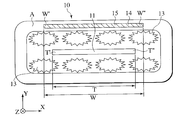
- FIG. 2 is a cross-sectional view of an optical fiber cord on the basis of a first embodiment of the present invention.
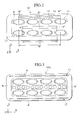
- FIG. 3 is a cross-sectional view of an optical fiber cord on the basis of a first changed embodiment of the first embodiment of the present invention.
- FIG. 4 is a cross-sectional view of an optical fiber ribbon cord on the basis of a second changed embodiment of the first embodiment of the present invention.
- FIG. 5 is an illustrative diagram showing a first method of manufacturing an optical fiber ribbon cord of the present invention.
- FIG. 6A is an illustrative diagram showing a second method of manufacturing an optical fiber ribbon cord of the present invention
- FIG. 6B is a partially enlarged cross-sectional view of the optical fiber ribbon cord extruded from a preceding extruder
- FIG. 6C is a partially enlarged cross-sectional view of the optical fiber ribbon cord extruded from a following extruder.
- FIG. 7A is an illustrative diagram showing a third method of manufacturing an optical fiber cord of the present invention
- FIG. 7B is a partially enlarged cross-sectional view of the optical fiber cord extruded from an extruder.
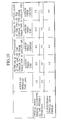
- FIG. 8 shows the measured results about force applied to the optical fiber cord pertaining to the first and second embodiments and a conventional one in the direction of the major axis and those about attenuation.
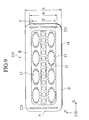
- FIG. 9 is a cross-sectional view of an optical fiber cord pertaining to a third embodiment of the present invention.
- FIG. 10 shows the measured results about force applied to the optical fiber cord pertaining to the second and third embodiments and the conventional one in the direction of the major axis and those about attenuation.
- FIGS. 11A and 11B are each cross-sectional view of an optical fiber cord pertaining to a fifth embodiment of the present invention.
- FIG. 11A shows an example with a cushion disposed in the direction of the major axis and
- FIG. 11B shows that with a cushion disposed all over the internal circumference of a sheath.
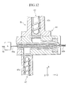
- FIG. 12 is a process diagram showing a first manufacturing method of an optical fiber cord pertaining to a sixth embodiment of the present invention.
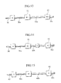
- FIG. 13 is a schematic process diagram showing a second manufacturing method of an optical fiber cord pertaining to the sixth embodiment of the present invention.
- FIG. 14 is a schematic process diagram showing a third manufacturing method of an optical fiber cord pertaining to the sixth embodiment of the present invention.
- FIG. 15 is a schematic process diagram showing a fourth manufacturing method of an optical fiber cord pertaining to the sixth embodiment of the present invention.
- FIG. 16 shows the measured results about force applied to the optical fiber cord pertaining to the fifth and sixth embodiments and the conventional one in the direction of the major axis, and also shows those about attenuation.
- FIG. 17 is a cross-sectional view of an optical fiber cord pertaining to a seventh embodiment of the present invention.
- FIG. 18 is a schematic process diagram showing a manufacturing method of an optical fiber cord pertaining to the eighth embodiment of the present invention.
- FIG. 19 shows the measured results about force applied to the optical fiber cord pertaining to the seventh and eighth embodiments and the conventional one in the direction of the major axis, and also shows those about attenuation.
- FIG. 20 is a cross-sectional view of an optical fiber cord pertaining to a ninth embodiment of the present invention.
- FIG. 21 is a schematic process diagram showing a manufacturing method of an optical fiber cord pertaining to the tenth embodiment of the present invention.
- FIG. 22 shows the measured results about attenuation in an optical fiber cord with inserted tape bodies according to the ninth and tenth embodiments, and in the conventional one.
- FIG. 2 is a cross-sectional view of an optical fiber ribbon cord on the basis of a first embodiment of the present invention.
- an optical fiber ribbon cord is depicted as 10 , in the center of which a multi-core fiber ribbon (hereafter referred to “fiber ribbon”) 11 having 12 fibers therein is disposed.
- a cross-section of the fiber ribbon 11 has an asymmetrical shape flat in the X-direction (first direction).
- Tension fibers 13 as a first tendency provider surround the exterior of the fiber ribbon 11 on both sides of the fiber ribbon 11 in order to provide rigidity such as tensile strength in the Y-direction (second direction) crossing X-direction of the fiber ribbon 11 , and further the exterior of them are covered with a sheath 14 .
- a tape body 15 As a second tendency provider in at least one side wall A.
- Young's modulus of the tape body 15 is selected to be higher than that of the sheath 14 , the tape body 15 having a flat cross-section, and preferably a larger thickness for enhancing the rigidity.
- the second tendency provider provides rigidity for its surroundings and itself performs elastic or buffer action. When the tape body 15 is disposed within the sheath, it can provide rigidity in its vicinity in the direction of the plane of the tape body 15 .
- the tape body 15 provides rigidity mainly in the Y-direction and reinforces the Y-directional rigidity of the fiber ribbon 11 .
- the material for the tape body 15 employed is a metal worked into the shape of a tape or a plastic formed into the shape of a tape. Even paper or unwoven cloth can be used if only rigidity can be obtained.
- length W in the direction of width of the tape body 15 is wider than length T in the direction of width of the fiber ribbon 11 , moreover both end portions W′, W′′ of the tape body 15 in the width direction are inserted in such a state that they extend farther than both end portions T′, T′′ of the fiber ribbon 11 .
- the fiber ribbon 11 is more resistant to bending and the rigidity can be obtained.
- FIG. 3 shows first changed embodiment of the first embodiment, and both end portions of a tape body 17 in its width direction (X-direction) extend even to side walls B, B′ of the sheath 18 in the direction of the major axis. And, since the tape bodies 17 are inserted in both side walls A, A′ of the sheath 18 in the direction of the minor axis (Y-direction), an optical fiber cord having higher bending rigidity compared with that of the first embodiment can be obtained.
- FIG. 4 shows second changed embodiment of the first embodiment, and a plurality of tape bodies with small width, for example 3 pieces, 20 , 21 , 22 are inserted. Even in the tape members small in width like this, if only the distance W between end portions 20 ′ and 22 ′ of the tape bodies 20 , 22 is made larger than the width T of a fiber ribbon 23 , bending rigidity against external force in the direction of the major axis of a sheath.
- variables may be appropriately selected from suitable ones on the basis of kind of the fiber ribbons, rigidity of sheath material, or sort of manufacturing methods, etc.
- the rigidity against bending is enhanced by the tape body with higher Young's modulus than that of the sheath, the force cannot be applied directly to the fiber ribbon even if external force is applied to the sheath especially in the direction of the major axis. Moreover, even if force making the sheath shrink longitudinally is applied at low temperature, increase in attenuation can be prevented because of uneasiness of bending by means of the tape body. Further, when external force is applied to the sheath in the direction of the major axis, rigidity can be obtained due to uneasiness of bending of the fiber ribbon.
- FIG. 5 is an illustrative diagram showing a method of manufacturing an optical fiber ribbon cord of the present invention.
- the optical fiber ribbon cord 25 comprises a plurality of tension fibers as first tendency provider juxtaposed longitudinally along about an optical fiber ribbon.
- the optical fiber ribbon cord 25 the exterior of which is covered with the sheath composed of a resin, is introduced into the center of an extruder 26 .
- the tape bodies 27 , 27 so as to be juxtaposed longitudinally (Z-direction) along about the exterior of the cord 25 .
- the cross-section of the fiber ribbon has the shape of an asymmetrically flat in the X-direction (first direction).
- the extruder 26 includes an inlet 26 a , and by passing the two tape bodies 27 , 27 as second tendency providers juxtaposed along about a ready-made optical fiber ribbon cord through a die 28 , the optical fiber ribbon cord 29 as shown in the first embodiment having the two tape bodies 27 , 27 inserted in the internal side walls in the direction of the minor axis (Y-direction) can be obtained.
- an optical fiber ribbon cord 29 which has high rigidity and is able to protect the optical fiber ribbon against the external force applied in the direction of the major axis of the sheath, can be easily manufactured using the ready-made optical fiber ribbon cord.
- FIG. 6 shows a first changed embodiment of the second embodiment
- FIG. 6A shows a part of manufacturing process where two extruders 30 , 31 are disposed in communication with each other.
- an optical fiber ribbon 32 is introduced in to the center of the extruder 30
- tension fibers 33 as first tendency providers are introduced longitudinally along about its exterior on both sides in the Y-direction.
- the extruder 30 includes an inlet 30 a for introducing a sheathing resin, and an optical fiber ribbon cord 35 is molded by being covered with the sheathing resin while passing through a die 34 .
- the optical fiber ribbon cord 35 is, at the downstream manufacturing line, introduced into the extruder 31 , and at the same time tape bodies 37 as second tendency providers are introduced being juxtaposed longitudinally along about the exterior thereof.
- the extruder 31 includes an inlet 31 a for introducing a sheathing resin, and an optical fiber ribbon cord 40 is molded by being covered with the sheathing resin 39 while passing through a die 38 .
- FIG. 7A shows a second changed embodiment of the second embodiment, and an extruder 42 includes 2 inlets, 42 a , 42 b for introducing sheathing resin.
- an optical fiber ribbon 43 In the middle level of the extruder 42 introduced is an optical fiber ribbon 43 , and along about the exterior and on both sides thereof introduced are tension fibers 44 as first tendency providers juxtaposed longitudinally in Y-direction, further about the exterior of them introduced is one tape body 45 as a tendency provider being juxtaposed longitudinally along about them.
- the same resin is introduced from the resin inlets 42 a , 42 b .
- the resin introduced from the resin inlet 42 a prevents the tension fibers 44 from integrating into one body with the tape body 45 by means of forming a resin layer outside of the tension fibers 44 at a die portion 47 .
- an optical fiber ribbon cord 48 as shown in FIG. 2 in the first embodiment can be obtained at the die portion 47 .
- FIG. 8 shows the measured results about attenuation of an optical fiber ribbon cord with an inserted tape body of the present invention and of a conventional one without any inserted tape body, when force is applied thereto in the direction of the major axis.
- the positions at which measurement has been made are an end of a fiber ribbon and the center of the fiber ribbon, and the force applied in the direction of the major axis were two kinds of force, 250N and 500N via an iron plate with width of 100 mm.
- wavelength of a light source for attenuation measurement was 1.55 ⁇ m.
- a fiber ribbon in the type of SM single mode with 12 fibers; tension fibers composed of 8 polyaramide fibers with 1420 deniers; tape bodies made of polypropylene with thickness of 30 ⁇ m, 4.2 mm in width, Young's modulus of 2000N/mm 2 , each one being inserted in both the side walls in the direction of the minor axis of a sheath.
- sheathing material used was a nonflammable polyolefin resin with a size of 2.5 mm ⁇ 5 mm on the outside, 1.5 mm ⁇ 4 mm on the inside, and Young's modulus of 200N/mm 2 .
- an optical fiber cord which has high bending rigidity, and where the optical fiber ribbon are protected against the external force applied in the direction of the major axis to a sheath, can be easily obtained using a ready-made conventional optical fiber ribbon cord. Further, since the two extruders are installed in the one manufacturing process, an optical fiber ribbon cord in which the optical fiber ribbon is kept undamaged can be manufactured continuously with ease. Still further, an optical fiber ribbon cord in which the optical fiber ribbon is kept undamaged can be manufactured continuously with ease by means of only one extruder.
- the optical fiber ribbon cord 210 pertaining to the present embodiment has the same structure as that of the first embodiment except for a tape body 225 , the explanation of common features is omitted.
- Each of tape bodies 225 , 225 is inserted in each of two opposing side walls A, A′ respectively in the direction of the major axis X of a sheath 14 .
- Young's modulus of the tape body 225 is selected to be higher than that of the sheath 14 , the tape body 225 having preferably a larger thickness for enhancing the rigidity.
- the material of the tape body 225 employed is a metal worked into the shape of a tape or a plastic formed into the shape of a tape. Even paper or unwoven cloth can be used if at least rigidity can be obtained.
- the length W in the width direction of the tape body 225 is longer than the internal distance T between the side walls B, B′ in the direction of the minor axis Y of the sheath and shorter than the thickness S of the cord.
- the rigidity against bending is enhanced by the tape body with higher Young's modulus than that of the sheath, the force cannot be applied directly to the fiber ribbon even if external force is applied to the sheath especially in the direction of the major axis. Even if force making the sheath shrink longitudinally is applied at low temperature, increase in attenuation can be prevented because of uneasiness of bending by means of the tape body.
- an optical fiber ribbon cord which has high bending rigidity, and where the optical fiber ribbon are protected against the external force applied in the direction of the major axis to a sheath, can be easily obtained using an optical fiber ribbon cord manufactured by prior art.
- an optical fiber ribbon cord which has high bending rigidity, and where the optical fiber ribbon are protected against the external force applied in the direction of the major axis X to a sheath, can be easily obtained using a ready-made optical fiber ribbon cord.
- an optical fiber ribbon cord 48 in which the optical fiber ribbon 43 is kept undamaged can be manufactured continuously with ease using only one extruder 42 .
- FIG. 10 shows the measured results about attenuation of an optical fiber ribbon cord with an inserted tape body of the present invention and of a conventional one without any inserted tape body, when force is applied thereto in the direction of the major axis X.
- the positions at which measurement has been made are an end of a fiber ribbon and the center of the fiber ribbon, and the force applied in the direction of the major axis were two kinds of force, 250N and 500N via an iron plate with width of 100 mm.
- wavelength of a light source for attenuation measurement was chosen to be 1.55 ⁇ m.
- the various dimensions of the optical fiber ribbon cord, which was used in the measurement, according to the present invention were: a fiber ribbon in the type of SM (single mode) with 12 fibers; tension fibers composed of 8 polyaramide fibers with 1420 deniers; tape bodies made of polypropylene with thickness of 30 ⁇ m, 11.0 mm and 2.0 mm in width, Young's modulus of 2000N/mm 2 , each one being inserted in both the side walls in the direction of the minor axis of a sheath.
- sheathing material used was a nonflammable polyolefin resin with a size of 2.5 mm ⁇ 5 mm on the outside, 1.5 mm ⁇ 4 mm on the inside, and Young's modulus of 200N/mm 2 .
- the optical fiber ribbon cords according to the present invention generated no attenuation as for the one with an inserted tape with 2.0 mm in width.
- attenuation remains as low as 0.05 dB in said experiment (measurement about attenuation), and it was recognized that increase in attenuation due to external force far hardly occurs than in conventional optical fiber ribbon cords.
- an optical fiber ribbon cord in which the optical fiber ribbon is kept undamaged can be manufactured continuously with ease.
- an optical fiber ribbon cord in which the optical fiber ribbon is kept undamaged can be manufactured continuously with ease using only one extruder.
- FIG. 11A An optical fiber ribbon cord pertaining to the present embodiment has across-sectional structure as shown in FIG. 11A.
- an optical fiber ribbon cord is depicted by numeral 310 ; in the center a multi-core fiber ribbon 11 having 12 fibers therein being disposed; tension fibers 13 for providing tensile strength in the direction of the minor axis surrounding the exterior of the fiber ribbon 11 ; cushion members 336 , 336 being disposed at both ends in the direction of the major axis (X-direction) of the fiber ribbon 11 also surrounding the fiber ribbon 11 ; and the exterior of them are covered with a sheath 14 .
- the cushion members 336 , 336 are fixed immovably to both ends 14 a , 14 a in the direction of the major axis X of the sheath 14 .
- the ends of the fiber ribbon 11 would always be protected by the cushion members 336 , 336 .
- FIG. 11B is a changed example of an optical fiber ribbon cord
- the optical fiber ribbon cord 315 is the same in structure as the optical fiber ribbon cord 310 in the fact that in the center disposed is a multimode fiber ribbon 11 having 12 fibers therein, and on both sides of the fiber ribbon also disposed ate tension fibers 13 in the direction of the minor axis Y upside and downside of the fiber ribbon, however, different in the fact that a cushion member 338 surrounds entirely the exterior of both the fiber ribbon 11 and the tension fibers 13 . Thereby, since the cushion member is effective against external force from all directions, the fiber ribbon can surely be protected against it.
- the cushion members 336 ( 338 ) have preferably lower hardness than that of the sheath 14 , and soft foamed plastic such as polyurethane, polyethylene, polyvinyl chloride are suitably used, but formations of cotton or fibers can also be usable. Besides, PVC, polyolefin resin, and polyamide resin are preferably used as the sheath material.
- the cushion members are fixed immovably to the longitudinal side walls in the interior of the sheath, the fiber ribbon can always be protected by the cushion members when external force is applied in the direction of the major axis Y of the sheath.
- a method of manufacturing an optical fiber ribbon cord of the fifth Embodiment of the present invention will be described on the basis of the process diagram shown in FIG. 12.
- a fiber ribbon 40 has been accomplished being juxtaposed longitudinally (Z-direction) with tension fibers as first tendency providers in the step A, and the fiber ribbon 40 a having the tension fibers is introduced into an extruder B.
- the extruder B includes a body 44 having an inlet 42 a for introducing sheathing resin 42 and an inlet 43 a for introducing cushion resin 43 , and simultaneously extruded are cushion resin 43 around the exterior of the fiber ribbon 40 a and sheathing resin 42 around the further exterior of them, and both are then thermally fusion-bonded to yield an optical fiber ribbon cord 40 b . Since the cushion member and the sheath are thermally fusion-bonded, there will be no chance for both to dislocate with each other after production.
- the simultaneous thermal fusion bonding shown in FIG. 12 is a method for manufacturing the optical fiber ribbon cord in which cushion resin 43 surrounds entirely the exterior of the fiber ribbon 40 a , on the other hand when the optical fiber ribbon cord in FIG. 11B is manufactured, such a die shaped as to extrude the cushion resin 43 only at both ends in the direction of the major axis of the fiber ribbon 40 a.
- a second method of manufacturing an optical fiber ribbon cord of the fifth Embodiment of the present invention will be described on the basis of the schematic process diagram shown in FIG. 13.
- a fiber ribbon 50 has been accomplished being juxtaposed longitudinally with tension fibers as first tendency providers in the step A, and the fiber ribbon 50 a having the tension fibers is introduced into an extruder B 1 .
- the extruder B 1 is a preceding extruder in the production lines, through which the cushion resin 51 is extruded.
- a fiber ribbon 50 b where the cushion member is fixed to the required position is then introduced into a following extruder B 2 .
- An optical fiber ribbon cord 50 c is manufactured by means of extruding the sheathing resin 52 through the following extruder B 2 . Since the cushion member and the sheath are thermally fusion-bonded, there will be no chance for both to dislocate with each other after production. Moreover, since observation of molded states such as dislocation of the molded cushion members is possible before extruding the sheathing resin through the extruder, the cushion members can be placed in the accurate position.
- manufacturing can be done while observing the molded states such as the dislocation of the molded cushion members before extruding the sheathing resin through the extruder.
- a third method of manufacturing an optical fiber ribbon cord of the fifth Embodiment of the present invention will be described on the basis of the schematic process diagram shown in FIG. 14. That is to say, even though a cushion member difficult for thermal fusion-bonding to a sheath is employed, adding a step C, where adhesive is applied on the portion of the cushion member having been extruded by the preceding extruder B 1 to be contacted to the inner surface of the sheath, after extruding cushion resin 51 through the preceding extruder B 1 , and before extruding sheathing resin 52 through the following extruder B 2 as shown in FIG. 14, will be able to make the cushion members fixed to the prescribed positions of the sheath.
- the cushion members can be fixed using adhesive to the prescribed positions of the sheath.
- a fourth method of manufacturing an optical fiber ribbon cord of the fifth embodiment of the present invention will be described on the basis of the schematic process diagram shown in FIG. 15.
- a fiber ribbon 60 has been accomplished being juxtaposed longitudinally with tension fibers in the step A, and the fiber ribbon 60 a having the tension fibers is then accomplished being juxtaposed longitudinally with fiber-like cushion members so as to be disposed at least in the major axis of the fiber ribbon in the interior of the sheath in the step D, and a fiber ribbon 60 b surrounded with the tension fibers and the cushion members can be obtained.
- the cushion members are thermally fusion-bonded with the sheath to yield an optical fiber ribbon cord 60 c .
- the cushion member is difficult for thermal fusion bonding with a sheath, it is preferable to use a cushion member on which adhesive is applied beforehand in the step D or to add a step in the lines for applying adhesive between the step D and the step B.
- the cushion member even if the cushion member is composed of fiber-like material unsuitable to extrusion molding, manufacturing an optical fiber ribbon cord in which external force can be always relieved will be possible. Moreover, even if the cushion member is unsuitable to extrusion molding, and even when the cushion member is difficult for thermal fusion bonding with the sheath, the cushion member will be fixed using adhesive to the predetermined position of the sheath. Further, even if the cushion member is unsuitable to extrusion molding, and even when the cushion member is difficult for thermal fusion bonding with the sheath, the cushion member will be securely fixed to the sheath by means of applying adhesive efficiently in a series of production flow.
- adhesive used in the present invention preferably used are polyurethane series, vinyl acetate resin series, epoxy series, chloroprene rubber series, etc.
- FIG. 16 shows the measured results about attenuation of the product according to the present invention and of a conventional one, when force is applied thereto in the direction of the major axis.
- the positions at which measurement has been made are an end of a fiber ribbon and the center of the fiber ribbon, and the force applied were two kinds of force, 250N and 500N via an iron plate with width of 100 mm.
- the increase by 0.2 dB in attenuation occurred at the end of the fiber ribbon, when 500N was applied to the conventional optical fiber ribbon cord.
- a seventh embodiment of the present invention will be described on the basis of FIG. 17.
- 410 is an optical fiber ribbon cord, in the center of which a multi-core fiber ribbon (hereafter referred to “fiber ribbon”) 11 having 12 fibers therein is disposed, and tension fibers 13 surround the fiber ribbon 11 on both sides of the fiber ribbon 11 in order to supply tensile strength in the direction of minor axis (Y-direction), and tension fibers 413 , 413 surround the fiber ribbon 11 at both ends in the direction of major axis (X-direction) of the fiber ribbon 11 , and further the exterior of them are covered with a sheath 14 .
- fiber ribbon multi-core fiber ribbon
- tension fibers 13 surround the fiber ribbon 11 on both sides of the fiber ribbon 11 in order to supply tensile strength in the direction of minor axis (Y-direction)
- tension fibers 413 , 413 surround the fiber ribbon 11 at both ends in the direction of major axis (X-direction) of the fiber ribbon 11 , and further the exterior of them are covered with a sheath 14 .
- the tension fibers 413 , 413 disposed at both ends in the direction of the major axis is applied with adhesive 415 on their surfaces to be contacted the inner surface of the sheath so as to be fixed immovably to both ends 14 a , 14 a in the direction of the major axis of the sheath 14 .
- the end portions of the fiber ribbon 11 will always be protected by the tension fibers 413 , 413 even when external force is applied in the direction of the major axis (in the direction of the arrows) of the sheath 14 .
- the external force in the direction of minor axis of the sheath 14 can be supported by the tension fibers 13 .
- adhesive 415 used are polyurethane series, vinyl acetate resin series, epoxy series, chloroprene rubber series, etc. and besides, PVC, polyolefin resin, and polyamide resin are preferably used as the sheath material.
- a method of manufacturing an optical fiber ribbon cord pertaining to the seventh Embodiment of the present invention will be described on the basis of the schematic process diagram shown in FIG. 18.
- a fiber ribbon 40 has been accomplished being juxtaposed longitudinally with tension fibers 13 , 413 in the step A. Then, in the step B, the tension fibers 413 are applied with adhesive 415 on their surfaces to be contacted the inner surface of the sheath.
- a fiber ribbon 40 a about which tension fibers 13 , 413 has been thus juxtaposed longitudinally is introduced into an extruder C.
- the extruder C includes a body 44 having an inlet 42 a for introducing sheathing resin 42 , and the sheathing resin 42 is extruded about the exterior of fiber ribbon 40 a to yield an optical fiber ribbon cord 40 b.
- FIG. 19 shows the measured results about attenuation of the product according to the present invention and of a conventional one, when force is applied thereto in the direction of the major axis, and the positions at which measurement has been made are an end of a fiber ribbon and the center of the fiber ribbon, and the force applied were two kinds of force, 250N and 500N via an iron plate with width of 100 mm.
- the increase by 0.2 dB in attenuation occurred at the end of the fiber ribbon, when 500N was applied to the conventional optical fiber ribbon cord.
- an optical fiber ribbon cord where the optical fiber ribbon are protected against the external force applied in the direction of the major axis to a sheath, can be easily obtained.
- an optical fiber ribbon cord is depicted by numeral 510 , in the center of which a multi-core fiber ribbon 11 having 12 fibers therein is disposed, and 2 sheets of reinforcement tape surrounding the fiber ribbon 11 are stuck on each other at both ends in X-direction.
- Tension fibers 13 surround the exterior of the fiber ribbon 11 on both sides of the fiber ribbon 11 in order to supply tensile strength in the direction of minor axis (Y-direction), and further the exterior of them are covered with a sheath 14 .
- stuck portions 512 a of the reinforcement tape 512 become rigid in such a constitution, rigidity against bending is increased, and external force applied in the direction of the major axis (in the direction of arrows) of the sheath 14 does not directly work on the fiber ribbon 11 because of cushioning function of the stuck portions 512 a.
- the reinforcement tape 512 has preferably the thickness larger than or equal to 10 ⁇ m in order to increase its rigidity, and further a material with a comparatively high melting point is suitable in order to endure the heat during extrusion preferably using polypropylene, polyethylene-terephthalate, polyimide, etc. Further, width of the reinforcement tape may be 1 mm to 2 mm larger than that of the fiber ribbon and width of the stuck portions 512 a may preferably be 0.5 mm to 1 mm.
- adhesive for sticking the reinforcement tape together used are polyurethane series, vinyl acetate resin series, epoxy series, chloroprene rubber series, etc. and PVC, polyolefin resin, and polyamide resin are used as the sheath material.
- a method of manufacturing an optical fiber ribbon cord pertaining to the ninth Embodiment of the present invention will be described on the basis of the schematic process diagram in FIG. 21.
- a fiber ribbon 40 is stuck to reinforcement tape 512 with adhesive in the step A to yield a fiber ribbon 40 a .
- a plurality of tension fibers 13 is juxtaposed longitudinally along about it in the step B.
- a fiber ribbon 40 b along about which tension fibers 13 are juxtaposed longitudinally is introduced into an extruder C.
- the extruder C includes a body 44 having an inlet 42 a for introducing sheathing resin 42 , and the sheathing resin 42 is extruded about the exterior of fiber ribbon 40 a to yield an optical fiber ribbon cord 40 c.
- FIG. 22 shows the measured results about attenuation of the product according to the present invention and of a conventional one, when force is applied thereto in the direction of the major axis, and the positions at which measurement has been made are an end of a fiber ribbon and the center of the fiber ribbon, and the force applied were two kinds of force, 250N and 500N via an iron plate with width of 100 mm.
- the increase by 0.2 dB in attenuation occurred at the end of the fiber ribbon, when 500N was applied to the conventional optical fiber ribbon cord.
- Fiber ribbon 12 fibers, SM fiber ribbon
- an optical fiber ribbon cord which has high rigidity against bending, and where the optical fiber ribbon are protected against the external force applied in the direction of the major axis to a sheath, can be easily obtained.
Landscapes
- Physics & Mathematics (AREA)
- General Physics & Mathematics (AREA)
- Optics & Photonics (AREA)
- Engineering & Computer Science (AREA)
- Manufacturing & Machinery (AREA)
- Surface Treatment Of Glass Fibres Or Filaments (AREA)
- Extrusion Moulding Of Plastics Or The Like (AREA)
Abstract
An optical fiber ribbon cord 10 comprising a plurality of tension fibers 13 juxtaposed along about an optical fiber ribbon 11 and a sheath 14 composed of a resin covering all the exteriors thereof, wherein at least one tape body 15 with higher Young's modulus than that of the sheath is inserted within the interior A of a side wall in the minor axis of the sheath.
Description
- 1. Field of the Invention
- The present invention relates to a method of manufacturing an optical fiber cord comprising a plurality of tension fibers juxtaposed longitudinally along about an optical fiber ribbon and a sheath composed of a resin covering all the exteriors thereof.
- 2. Description of the Related Art
- Known in the art is an optical fiber ribbon cord comprising a plurality of optical fibers bound in the shape of a tape and all the exteriors thereof are covered with a sheath in the shape of a rectangle or an oval, because of easy joining with a connector and the advantage of equalizing every transmission line length of optical fibers. FIG. 1A and FIG. 1B are the cross-sectional views of the conventional optical fiber ribbon cord at rest just as manufactured and of the optical fiber ribbon cord in operation, respectively. In FIG. 1A, the optical
fiber ribbon cord 1 comprises afiber ribbon 2 disposed in the center with multi-fibers (12 fibers),tension fibers 3 juxtaposed longitudinally (Z-direction) along about thefiber ribbon 2 in order to supply tensile strength, and asheath 4 covering them. - The
tension fibers 3 carry out the functions of a cushion for preventing external force from direct application via thesheath 4 onto thefiber ribbon 2, since thetension fibers 3 are located between thefiber ribbon 2 and thesheath 4. - However, in the conventional optical
fiber ribbon cord 1, it is difficult to keep thetension fibers 3 staying stably in the direction of the major axis (X-direction) of thefiber ribbon 2 during operation, since the tension fibers are liable to move upward or downward in the direction of the minor axis (Y-direction) of the cord from thefiber ribbon 2 as a borderline, as shown in FIG. 1B. - Thus, when external force is applied from the direction of the major axis, the
fiber ribbon 2 directly contacts thesheath 4 to generate large bending of fibers a, b, which are located at both ends of a plurality of fibers in thefiber ribbon 2, resulting in increase in attenuation or occasional interruption of signal transmission with breaking of the fibers. - In order to overcome such a situation, it was considered that the distance from the edge of the fiber ribbon to the fiber at the end would be longer, but there has still remained such a problem for practical use that enlargement of the tape width results in being mismatched with the size of a fiber ribbon insertion portion of a connector.
- The present invention has been made in consideration of such circumstances, and according to the present invention provided are an optical fiber ribbon cord and a method of manufacturing the same, wherein enhancement of the transmission characteristics, especially, prevention of increase in attenuation at low temperature has been attempted by preventing external force from being applied directly to an optical fiber ribbon keeping the fiber ribbon from bending even when the external force is applied to a sheath.
- According to a first technical aspect of the present invention, an optical fiber ribbon cord comprises a fiber ribbon including a plurality of optical fibers, the fiber ribbon having a cross-section which is flat in the first direction, a plurality of the first tendency providers juxtaposed along about the optical fiber ribbon, a sheath covering the exteriors of the fiber ribbon and the first tendency providers, and at least one second tendency provider inserted in the sheath, wherein the second tendency provider provides rigidity at least in the direction crossing the first direction.
- According to a second technical aspect of the present invention, the second tendency provider is disposed by the side of an end portion in the first direction of the fiber ribbon.
- According to a third technical aspect of the present invention, in the first technical aspect, the second tendency provider is a cushion member and disposed by the side of an end portion in the first direction of the fiber ribbon.
- According to a fourth technical aspect of the present invention, in the first technical aspect, the first tendency providers adhere firmly to the interior of the sheath at least by the side of an end portion in the first direction of the fiber ribbon.
- According to a fifth technical aspect of the present invention, in the first technical aspect, the optical fiber ribbon cord further comprises reinforcement tapes which are stuck together in order to surround the fiber ribbon.
- According to a sixth technical aspect of the present invention, a method of manufacturing optical fiber ribbon cords comprises steps of introducing a optical fiber cord, including both a fiber ribbon with a cross-section flat in the first direction having a plurality of optical fibers and a plurality of first tendency providers juxtaposed along about the optical fiber ribbon, into an extruder; introducing at least one second tendency provider into the extruder so as to be juxtaposed along the optical fiber ribbon cord in the direction crossing the first direction; and extruding sheathing resin through the extruder, and coating the optical fiber ribbon cord and the first tendency providers with the sheathing resin.
- According to a seventh technical aspect of the present invention, in the step of introducing the second tendency provider in the sixth technical aspect into the extruder, the second tendency provider is introduced into the extruder so as to be juxtaposed by the side of an end portion in the first direction of the fiber ribbon.
- According to a eighth technical aspect of the present invention, a method of manufacturing optical fiber ribbon cords comprises a step of juxtaposing a plurality of first tendency providers along about a fiber ribbon which has a cross-section flat in the first direction and a plurality of optical fibers, and introducing them into an extruder; a step of juxtaposing at least one cushion member along the fiber ribbon and the first tendency providers to introduce them into the extruder; and a step of extruding sheathing resin through the extruder to thermally fusion-bond the fiber ribbon, the first tendency providers and the cushion member.
- According to a ninth technical aspect of the present invention, a method of manufacturing optical fiber ribbon cords comprises a step of juxtaposing a plurality of first tendency providers along about an optical fiber ribbon which has a cross-section flat in the first direction and a plurality of optical fibers, the first tendency providers being disposed at least by the side of an end portion in the first direction of the fiber ribbon; s step of applying adhesive to portions, which will contact to the interior of a sheath, of the first tendency providers disposed by the side of the end portion in the first direction of the fiber ribbon; and a step of extrusion-coating the exteriors of the fiber ribbon and a plurality of the first tendency providers with sheathing resin.
- According to a tenth technical aspect of the present invention, a method of manufacturing optical fiber ribbon cords comprises a step of sticking reinforcement tapes together in order to surround a fiber ribbon which has a cross-section flat in the first direction and a plurality of optical fibers; a step of juxtaposing a plurality of first tendency providers along about the fiber ribbon; and a step of extrusion-coating the exteriors of the fiber ribbon, the reinforcement tape and a plurality of the first tendency providers with sheathing resin.
- FIG. 1A and FIG. 1B are the cross-sectional views of the conventional optical fiber ribbon cord at rest just as manufactured and of the optical fiber ribbon cord in operation, respectively.
- FIG. 2 is a cross-sectional view of an optical fiber cord on the basis of a first embodiment of the present invention.
- FIG. 3 is a cross-sectional view of an optical fiber cord on the basis of a first changed embodiment of the first embodiment of the present invention.
- FIG. 4 is a cross-sectional view of an optical fiber ribbon cord on the basis of a second changed embodiment of the first embodiment of the present invention.
- FIG. 5 is an illustrative diagram showing a first method of manufacturing an optical fiber ribbon cord of the present invention.
- FIG. 6A is an illustrative diagram showing a second method of manufacturing an optical fiber ribbon cord of the present invention; FIG. 6B is a partially enlarged cross-sectional view of the optical fiber ribbon cord extruded from a preceding extruder; FIG. 6C is a partially enlarged cross-sectional view of the optical fiber ribbon cord extruded from a following extruder.
- FIG. 7A is an illustrative diagram showing a third method of manufacturing an optical fiber cord of the present invention; FIG. 7B is a partially enlarged cross-sectional view of the optical fiber cord extruded from an extruder.
- FIG. 8 shows the measured results about force applied to the optical fiber cord pertaining to the first and second embodiments and a conventional one in the direction of the major axis and those about attenuation.
- FIG. 9 is a cross-sectional view of an optical fiber cord pertaining to a third embodiment of the present invention.
- FIG. 10 shows the measured results about force applied to the optical fiber cord pertaining to the second and third embodiments and the conventional one in the direction of the major axis and those about attenuation.
- FIGS. 11A and 11B are each cross-sectional view of an optical fiber cord pertaining to a fifth embodiment of the present invention; FIG. 11A shows an example with a cushion disposed in the direction of the major axis and FIG. 11B shows that with a cushion disposed all over the internal circumference of a sheath.
- FIG. 12 is a process diagram showing a first manufacturing method of an optical fiber cord pertaining to a sixth embodiment of the present invention.
- FIG. 13 is a schematic process diagram showing a second manufacturing method of an optical fiber cord pertaining to the sixth embodiment of the present invention.
- FIG. 14 is a schematic process diagram showing a third manufacturing method of an optical fiber cord pertaining to the sixth embodiment of the present invention.
- FIG. 15 is a schematic process diagram showing a fourth manufacturing method of an optical fiber cord pertaining to the sixth embodiment of the present invention.
- FIG. 16 shows the measured results about force applied to the optical fiber cord pertaining to the fifth and sixth embodiments and the conventional one in the direction of the major axis, and also shows those about attenuation.
- FIG. 17 is a cross-sectional view of an optical fiber cord pertaining to a seventh embodiment of the present invention.
- FIG. 18 is a schematic process diagram showing a manufacturing method of an optical fiber cord pertaining to the eighth embodiment of the present invention.
- FIG. 19 shows the measured results about force applied to the optical fiber cord pertaining to the seventh and eighth embodiments and the conventional one in the direction of the major axis, and also shows those about attenuation.
- FIG. 20 is a cross-sectional view of an optical fiber cord pertaining to a ninth embodiment of the present invention.
- FIG. 21 is a schematic process diagram showing a manufacturing method of an optical fiber cord pertaining to the tenth embodiment of the present invention.
- FIG. 22 shows the measured results about attenuation in an optical fiber cord with inserted tape bodies according to the ninth and tenth embodiments, and in the conventional one.
- First Embodiment
- The structure of an optical fiber cord of the present invention will be described on the basis of FIG. 2 to FIG. 4. FIG. 2 is a cross-sectional view of an optical fiber ribbon cord on the basis of a first embodiment of the present invention. In FIG. 2, an optical fiber ribbon cord is depicted as 10, in the center of which a multi-core fiber ribbon (hereafter referred to “fiber ribbon”) 11 having 12 fibers therein is disposed. A cross-section of the
fiber ribbon 11 has an asymmetrical shape flat in the X-direction (first direction).Tension fibers 13 as a first tendency provider surround the exterior of thefiber ribbon 11 on both sides of thefiber ribbon 11 in order to provide rigidity such as tensile strength in the Y-direction (second direction) crossing X-direction of thefiber ribbon 11, and further the exterior of them are covered with asheath 14. - In the Y-direction of the fiber ribbon, that is to say, in the direction of the minor axis (Y-direction) of the
sheath 14, inserted is atape body 15 as a second tendency provider in at least one side wall A. Young's modulus of thetape body 15 is selected to be higher than that of thesheath 14, thetape body 15 having a flat cross-section, and preferably a larger thickness for enhancing the rigidity. In the present invention, the second tendency provider provides rigidity for its surroundings and itself performs elastic or buffer action. When thetape body 15 is disposed within the sheath, it can provide rigidity in its vicinity in the direction of the plane of thetape body 15. In the present embodiment, thetape body 15 provides rigidity mainly in the Y-direction and reinforces the Y-directional rigidity of thefiber ribbon 11. As the material for thetape body 15 employed is a metal worked into the shape of a tape or a plastic formed into the shape of a tape. Even paper or unwoven cloth can be used if only rigidity can be obtained. - By inserting the
tape body 15 like this into thesheath 14, bending of thefiber ribbon 11 can be reduced when external force is applied directly to thecord 10 in the direction of the major axis X, and the direct application of stress to the fiber ribbon can be avoided. Further, since the sheath has also turned difficult to shrink by means of the tape body, increase in attenuation due to bending of the fiber ribbon owing to shrinkage of the sheath at a low temperature can be avoided, even though such a force as to make the sheath shrink longitudinally may be applied thereon at the low temperature. - Further, length W in the direction of width of the
tape body 15 is wider than length T in the direction of width of thefiber ribbon 11, moreover both end portions W′, W″ of thetape body 15 in the width direction are inserted in such a state that they extend farther than both end portions T′, T″ of thefiber ribbon 11. Thereby, when external force is applied in the direction of major axis X, thefiber ribbon 11 is more resistant to bending and the rigidity can be obtained. - First Changed Embodiment
- FIG. 3 shows first changed embodiment of the first embodiment, and both end portions of a
tape body 17 in its width direction (X-direction) extend even to side walls B, B′ of the sheath 18 in the direction of the major axis. And, since thetape bodies 17 are inserted in both side walls A, A′ of the sheath 18 in the direction of the minor axis (Y-direction), an optical fiber cord having higher bending rigidity compared with that of the first embodiment can be obtained. - Second Changed Embodiment
- FIG. 4 shows second changed embodiment of the first embodiment, and a plurality of tape bodies with small width, for example 3 pieces, 20, 21, 22 are inserted. Even in the tape members small in width like this, if only the distance W between
end portions 20′ and 22′ of thetape bodies fiber ribbon 23, bending rigidity against external force in the direction of the major axis of a sheath. - As mentioned above, although there can be thought of various changes in length of the tape bodies in the direction of width, the number of inserted tape bodies, or the location of disposition, variables may be appropriately selected from suitable ones on the basis of kind of the fiber ribbons, rigidity of sheath material, or sort of manufacturing methods, etc.
- According to the first Embodiment of the present invention, since the rigidity against bending is enhanced by the tape body with higher Young's modulus than that of the sheath, the force cannot be applied directly to the fiber ribbon even if external force is applied to the sheath especially in the direction of the major axis. Moreover, even if force making the sheath shrink longitudinally is applied at low temperature, increase in attenuation can be prevented because of uneasiness of bending by means of the tape body. Further, when external force is applied to the sheath in the direction of the major axis, rigidity can be obtained due to uneasiness of bending of the fiber ribbon.
- Second Embodiment
- A method of manufacturing an optical fiber cord pertaining to the first Embodiment of the present invention will be described on the basis of FIG. 5-FIG. 7. FIG. 5 is an illustrative diagram showing a method of manufacturing an optical fiber ribbon cord of the present invention.
- In FIG. 5, the optical
fiber ribbon cord 25 comprises a plurality of tension fibers as first tendency provider juxtaposed longitudinally along about an optical fiber ribbon. The opticalfiber ribbon cord 25, the exterior of which is covered with the sheath composed of a resin, is introduced into the center of anextruder 26. Also introduced are thetape bodies cord 25. Besides, the cross-section of the fiber ribbon has the shape of an asymmetrically flat in the X-direction (first direction). - The
extruder 26 includes aninlet 26 a, and by passing the twotape bodies die 28, the opticalfiber ribbon cord 29 as shown in the first embodiment having the twotape bodies - Thereby, an optical
fiber ribbon cord 29, which has high rigidity and is able to protect the optical fiber ribbon against the external force applied in the direction of the major axis of the sheath, can be easily manufactured using the ready-made optical fiber ribbon cord. - First Changed Embodiment
- FIG. 6 shows a first changed embodiment of the second embodiment, and FIG. 6A shows a part of manufacturing process where two
extruders optical fiber ribbon 32 is introduced in to the center of theextruder 30, andtension fibers 33 as first tendency providers are introduced longitudinally along about its exterior on both sides in the Y-direction. Theextruder 30 includes aninlet 30 a for introducing a sheathing resin, and an opticalfiber ribbon cord 35 is molded by being covered with the sheathing resin while passing through adie 34. - In the cross-section of the optical
fiber ribbon cord 35 at the time after having passed though thedie 34, as shown in FIG. 6B, there are formed anoptical fiber ribbon 32 in the middle,tension fibers 33 outside thereof, asheathing resin 36 further outside of them all. - The optical
fiber ribbon cord 35 is, at the downstream manufacturing line, introduced into theextruder 31, and at the sametime tape bodies 37 as second tendency providers are introduced being juxtaposed longitudinally along about the exterior thereof. Theextruder 31 includes aninlet 31 a for introducing a sheathing resin, and an opticalfiber ribbon cord 40 is molded by being covered with thesheathing resin 39 while passing through adie 38. - In the cross-section of the optical
fiber ribbon cord 40 after having passed though thedie 38, as shown in FIG. 6C, there are formed in a multi-layered form anoptical fiber ribbon 32 in the center,tension fibers 33 outside thereof, asheathing resin 36, atape body 37, asheathing resin 39 further outside of them all. - Since the two
extruders fiber ribbon cord 40 in which theoptical fiber ribbon 32 is kept undamaged can be manufactured continuously with ease. - Second Changed Embodiment
- FIG. 7A shows a second changed embodiment of the second embodiment, and an
extruder 42 includes 2 inlets, 42 a, 42 b for introducing sheathing resin. In the middle level of theextruder 42 introduced is anoptical fiber ribbon 43, and along about the exterior and on both sides thereof introduced aretension fibers 44 as first tendency providers juxtaposed longitudinally in Y-direction, further about the exterior of them introduced is onetape body 45 as a tendency provider being juxtaposed longitudinally along about them. - The same resin is introduced from the
resin inlets resin inlet 42 a prevents thetension fibers 44 from integrating into one body with thetape body 45 by means of forming a resin layer outside of thetension fibers 44 at adie portion 47. Then, by introducingresin 46 from theresin inlet 42 b, an opticalfiber ribbon cord 48 as shown in FIG. 2 in the first embodiment can be obtained at thedie portion 47. - In the cross-section of the optical
fiber ribbon cord 48 after having passed though thedie 47, as shown in FIG. 7B, there are formed in a multi-layered form anoptical fiber ribbon 43 in the middle layer,tension fibers 44 on both the outsides thereof, atape body 45 and asheathing resin 46 further outside of them all. Thereby, an opticalfiber ribbon cord 48, in which theoptical fiber ribbon 43 is kept undamaged can be easily manufactured by the only oneextruder 42. - FIG. 8 shows the measured results about attenuation of an optical fiber ribbon cord with an inserted tape body of the present invention and of a conventional one without any inserted tape body, when force is applied thereto in the direction of the major axis. In the table, the positions at which measurement has been made are an end of a fiber ribbon and the center of the fiber ribbon, and the force applied in the direction of the major axis were two kinds of force, 250N and 500N via an iron plate with width of 100 mm. Besides, wavelength of a light source for attenuation measurement was 1.55 μm.
- Conditions used in the measurement according to the present invention were as follows:
- a fiber ribbon in the type of SM (single mode) with 12 fibers; tension fibers composed of 8 polyaramide fibers with 1420 deniers; tape bodies made of polypropylene with thickness of 30 μm, 4.2 mm in width, Young's modulus of 2000N/mm 2, each one being inserted in both the side walls in the direction of the minor axis of a sheath.
- As sheathing material used was a nonflammable polyolefin resin with a size of 2.5 mm×5 mm on the outside, 1.5 mm×4 mm on the inside, and Young's modulus of 200N/mm 2.
- As seen in FIG. 8, the increase by 0.2 dB in attenuation occurred at the end of the fiber ribbon, when 500N was applied to the conventional optical fiber ribbon cord. However, in the optical fiber ribbon cord according to the present invention generated no attenuation at the end of the fiber ribbon even on the same conditions.
- According to the present embodiment, an optical fiber cord, which has high bending rigidity, and where the optical fiber ribbon are protected against the external force applied in the direction of the major axis to a sheath, can be easily obtained using a ready-made conventional optical fiber ribbon cord. Further, since the two extruders are installed in the one manufacturing process, an optical fiber ribbon cord in which the optical fiber ribbon is kept undamaged can be manufactured continuously with ease. Still further, an optical fiber ribbon cord in which the optical fiber ribbon is kept undamaged can be manufactured continuously with ease by means of only one extruder.
- Third Embodiment
- A structure of an optical fiber ribbon cord will be described on the basis of FIG. 9.
- Since, the optical
fiber ribbon cord 210 pertaining to the present embodiment has the same structure as that of the first embodiment except for atape body 225, the explanation of common features is omitted. - Each of
tape bodies sheath 14. Young's modulus of thetape body 225 is selected to be higher than that of thesheath 14, thetape body 225 having preferably a larger thickness for enhancing the rigidity. And as the material of thetape body 225 employed is a metal worked into the shape of a tape or a plastic formed into the shape of a tape. Even paper or unwoven cloth can be used if at least rigidity can be obtained. - By inserting the
tape body 225 like this into thesheath 14, bending of thefiber ribbon 11 can be reduced when external force in the direction of the major axis is applied directly to thecord 210, and the direct application of the force to the fiber ribbon can be avoided. Since the sheath does not shrink by means of the tape body and the fiber ribbon has turned difficult to bend, increase in attenuation at a low temperature can be avoided, even though such a force as to make the sheath shrink longitudinally may be applied thereon at the low temperature. - Further, the length W in the width direction of the
tape body 225 is longer than the internal distance T between the side walls B, B′ in the direction of the minor axis Y of the sheath and shorter than the thickness S of the cord. Thereby, when external force is applied in the direction of major axis, thefiber ribbon 11 is more resistant to bending and the rigidity can be obtained. - Namely, according to the present embodiment, since the rigidity against bending is enhanced by the tape body with higher Young's modulus than that of the sheath, the force cannot be applied directly to the fiber ribbon even if external force is applied to the sheath especially in the direction of the major axis. Even if force making the sheath shrink longitudinally is applied at low temperature, increase in attenuation can be prevented because of uneasiness of bending by means of the tape body.
- Moreover, an optical fiber ribbon cord, which has high bending rigidity, and where the optical fiber ribbon are protected against the external force applied in the direction of the major axis to a sheath, can be easily obtained using an optical fiber ribbon cord manufactured by prior art.
- Fourth Embodiment
- Since a method of manufacturing an optical fiber ribbon cord pertaining to the third Embodiment of the present invention is the same as those in the second Embodiment shown in FIG. 5-FIG. 7, the explanation about the common features will be omitted.
- According to the manufacturing method shown in FIG. 5, an optical fiber ribbon cord, which has high bending rigidity, and where the optical fiber ribbon are protected against the external force applied in the direction of the major axis X to a sheath, can be easily obtained using a ready-made optical fiber ribbon cord.
- According to the manufacturing method shown in FIG. 6, since the two
extruders fiber ribbon cord 40 in which theoptical fiber ribbon 32 is kept undamaged can be manufactured continuously with ease. - According to the manufacturing method shown in FIG. 7, an optical
fiber ribbon cord 48 in which theoptical fiber ribbon 43 is kept undamaged can be manufactured continuously with ease using only oneextruder 42. - FIG. 10 shows the measured results about attenuation of an optical fiber ribbon cord with an inserted tape body of the present invention and of a conventional one without any inserted tape body, when force is applied thereto in the direction of the major axis X. In the figure, the positions at which measurement has been made are an end of a fiber ribbon and the center of the fiber ribbon, and the force applied in the direction of the major axis were two kinds of force, 250N and 500N via an iron plate with width of 100 mm. Besides, wavelength of a light source for attenuation measurement was chosen to be 1.55 μm.
- The various dimensions of the optical fiber ribbon cord, which was used in the measurement, according to the present invention were: a fiber ribbon in the type of SM (single mode) with 12 fibers; tension fibers composed of 8 polyaramide fibers with 1420 deniers; tape bodies made of polypropylene with thickness of 30 μm, 11.0 mm and 2.0 mm in width, Young's modulus of 2000N/mm 2, each one being inserted in both the side walls in the direction of the minor axis of a sheath. Moreover, as sheathing material used was a nonflammable polyolefin resin with a size of 2.5 mm×5 mm on the outside, 1.5 mm×4 mm on the inside, and Young's modulus of 200N/mm2.
- As seen in FIG. 10, the increase by 0.2 dB in attenuation occurred at the end of the fiber ribbon as a force of 500 N was applied to the conventional optical fiber ribbon cord. However, in the optical fiber ribbon cords according to the present invention generated no attenuation as for the one with an inserted tape with 2.0 mm in width. Further, even as for the one with an inserted tape with 1.0 mm in width narrower than the width (1.5 mm) on the inside of the cord in the direction of the minor axis, attenuation remains as low as 0.05 dB in said experiment (measurement about attenuation), and it was recognized that increase in attenuation due to external force far hardly occurs than in conventional optical fiber ribbon cords.
- According to the present embodiment, since the two extruders are installed in the one manufacturing lines, an optical fiber ribbon cord in which the optical fiber ribbon is kept undamaged can be manufactured continuously with ease.
- And, an optical fiber ribbon cord in which the optical fiber ribbon is kept undamaged can be manufactured continuously with ease using only one extruder.
- Fifth Embodiment
- A fifth embodiment of the present invention will be described. An optical fiber ribbon cord pertaining to the present embodiment has across-sectional structure as shown in FIG. 11A. In the figure, an optical fiber ribbon cord is depicted by
numeral 310; in the center amulti-core fiber ribbon 11 having 12 fibers therein being disposed;tension fibers 13 for providing tensile strength in the direction of the minor axis surrounding the exterior of thefiber ribbon 11;cushion members fiber ribbon 11 also surrounding thefiber ribbon 11; and the exterior of them are covered with asheath 14. - The
cushion members sheath 14. Thus, even if external force is applied in the direction of the major axis (X-direction shown by arrows) to thesheath 14, the ends of thefiber ribbon 11 would always be protected by thecushion members - FIG. 11B is a changed example of an optical fiber ribbon cord, and the optical
fiber ribbon cord 315 is the same in structure as the opticalfiber ribbon cord 310 in the fact that in the center disposed is amultimode fiber ribbon 11 having 12 fibers therein, and on both sides of the fiber ribbon also disposed atetension fibers 13 in the direction of the minor axis Y upside and downside of the fiber ribbon, however, different in the fact that acushion member 338 surrounds entirely the exterior of both thefiber ribbon 11 and thetension fibers 13. Thereby, since the cushion member is effective against external force from all directions, the fiber ribbon can surely be protected against it. - The cushion members 336 (338) have preferably lower hardness than that of the
sheath 14, and soft foamed plastic such as polyurethane, polyethylene, polyvinyl chloride are suitably used, but formations of cotton or fibers can also be usable. Besides, PVC, polyolefin resin, and polyamide resin are preferably used as the sheath material. - According to the present embodiment, since the cushion members are fixed immovably to the longitudinal side walls in the interior of the sheath, the fiber ribbon can always be protected by the cushion members when external force is applied in the direction of the major axis Y of the sheath.
- Sixth Embodiment
- A method of manufacturing an optical fiber ribbon cord of the fifth Embodiment of the present invention will be described on the basis of the process diagram shown in FIG. 12. A
fiber ribbon 40 has been accomplished being juxtaposed longitudinally (Z-direction) with tension fibers as first tendency providers in the step A, and thefiber ribbon 40 a having the tension fibers is introduced into an extruder B. The extruder B includes abody 44 having aninlet 42 a for introducingsheathing resin 42 and aninlet 43 a for introducingcushion resin 43, and simultaneously extruded arecushion resin 43 around the exterior of thefiber ribbon 40 a andsheathing resin 42 around the further exterior of them, and both are then thermally fusion-bonded to yield an opticalfiber ribbon cord 40 b. Since the cushion member and the sheath are thermally fusion-bonded, there will be no chance for both to dislocate with each other after production. - The simultaneous thermal fusion bonding shown in FIG. 12 is a method for manufacturing the optical fiber ribbon cord in which
cushion resin 43 surrounds entirely the exterior of thefiber ribbon 40 a, on the other hand when the optical fiber ribbon cord in FIG. 11B is manufactured, such a die shaped as to extrude thecushion resin 43 only at both ends in the direction of the major axis of thefiber ribbon 40 a. - Since the cushion member and the sheath can be extruded at the same time to be fusion-bonded with each other, manufacturing processes are never complicated.
- A second method of manufacturing an optical fiber ribbon cord of the fifth Embodiment of the present invention will be described on the basis of the schematic process diagram shown in FIG. 13. A
fiber ribbon 50 has been accomplished being juxtaposed longitudinally with tension fibers as first tendency providers in the step A, and thefiber ribbon 50 a having the tension fibers is introduced into an extruder B1. The extruder B1 is a preceding extruder in the production lines, through which thecushion resin 51 is extruded. - A
fiber ribbon 50 b where the cushion member is fixed to the required position is then introduced into a following extruder B2. An opticalfiber ribbon cord 50 c is manufactured by means of extruding thesheathing resin 52 through the following extruder B2. Since the cushion member and the sheath are thermally fusion-bonded, there will be no chance for both to dislocate with each other after production. Moreover, since observation of molded states such as dislocation of the molded cushion members is possible before extruding the sheathing resin through the extruder, the cushion members can be placed in the accurate position. - According to the present embodiment, manufacturing can be done while observing the molded states such as the dislocation of the molded cushion members before extruding the sheathing resin through the extruder.
- A third method of manufacturing an optical fiber ribbon cord of the fifth Embodiment of the present invention will be described on the basis of the schematic process diagram shown in FIG. 14. That is to say, even though a cushion member difficult for thermal fusion-bonding to a sheath is employed, adding a step C, where adhesive is applied on the portion of the cushion member having been extruded by the preceding extruder B 1 to be contacted to the inner surface of the sheath, after extruding
cushion resin 51 through the preceding extruder B1, and before extrudingsheathing resin 52 through the following extruder B2 as shown in FIG. 14, will be able to make the cushion members fixed to the prescribed positions of the sheath. - Therefore, according to the present embodiment, even though a cushion member difficult for thermal fusion bonding to a sheath is employed, the cushion members can be fixed using adhesive to the prescribed positions of the sheath.
- A fourth method of manufacturing an optical fiber ribbon cord of the fifth embodiment of the present invention will be described on the basis of the schematic process diagram shown in FIG. 15. A
fiber ribbon 60 has been accomplished being juxtaposed longitudinally with tension fibers in the step A, and thefiber ribbon 60 a having the tension fibers is then accomplished being juxtaposed longitudinally with fiber-like cushion members so as to be disposed at least in the major axis of the fiber ribbon in the interior of the sheath in the step D, and afiber ribbon 60 b surrounded with the tension fibers and the cushion members can be obtained. - By extruding
sheathing resin 61 is extruded through an extruder B, the cushion members are thermally fusion-bonded with the sheath to yield an opticalfiber ribbon cord 60 c. When the cushion member is difficult for thermal fusion bonding with a sheath, it is preferable to use a cushion member on which adhesive is applied beforehand in the step D or to add a step in the lines for applying adhesive between the step D and the step B. - According to the present embodiment, even if the cushion member is composed of fiber-like material unsuitable to extrusion molding, manufacturing an optical fiber ribbon cord in which external force can be always relieved will be possible. Moreover, even if the cushion member is unsuitable to extrusion molding, and even when the cushion member is difficult for thermal fusion bonding with the sheath, the cushion member will be fixed using adhesive to the predetermined position of the sheath. Further, even if the cushion member is unsuitable to extrusion molding, and even when the cushion member is difficult for thermal fusion bonding with the sheath, the cushion member will be securely fixed to the sheath by means of applying adhesive efficiently in a series of production flow.
- As adhesive used in the present invention, preferably used are polyurethane series, vinyl acetate resin series, epoxy series, chloroprene rubber series, etc.
- FIG. 16 shows the measured results about attenuation of the product according to the present invention and of a conventional one, when force is applied thereto in the direction of the major axis. The positions at which measurement has been made are an end of a fiber ribbon and the center of the fiber ribbon, and the force applied were two kinds of force, 250N and 500N via an iron plate with width of 100 mm. As seen in this FIG. 16, the increase by 0.2 dB in attenuation occurred at the end of the fiber ribbon, when 500N was applied to the conventional optical fiber ribbon cord.
- Seventh Embodiment
- A seventh embodiment of the present invention will be described on the basis of FIG. 17.
- In FIG. 17, 410 is an optical fiber ribbon cord, in the center of which a multi-core fiber ribbon (hereafter referred to “fiber ribbon”) 11 having 12 fibers therein is disposed, and
tension fibers 13 surround thefiber ribbon 11 on both sides of thefiber ribbon 11 in order to supply tensile strength in the direction of minor axis (Y-direction), andtension fibers fiber ribbon 11 at both ends in the direction of major axis (X-direction) of thefiber ribbon 11, and further the exterior of them are covered with asheath 14. - The
tension fibers sheath 14. Thus, the end portions of thefiber ribbon 11 will always be protected by thetension fibers sheath 14. It is noted that the external force in the direction of minor axis of thesheath 14 can be supported by thetension fibers 13. - As
adhesive 415 used are polyurethane series, vinyl acetate resin series, epoxy series, chloroprene rubber series, etc. and besides, PVC, polyolefin resin, and polyamide resin are preferably used as the sheath material. - Thus, since tension fibers are fixed with adhesive to both longitudinal side walls in the interior of the sheath, the fiber ribbon will always be protected by the tension fibers even when external force is applied in the direction of the major axis of the sheath.
- Eighth Embodiment
- A method of manufacturing an optical fiber ribbon cord pertaining to the seventh Embodiment of the present invention will be described on the basis of the schematic process diagram shown in FIG. 18. A
fiber ribbon 40 has been accomplished being juxtaposed longitudinally withtension fibers tension fibers 413 are applied with adhesive 415 on their surfaces to be contacted the inner surface of the sheath. - A
fiber ribbon 40 a about whichtension fibers body 44 having aninlet 42 a for introducingsheathing resin 42, and thesheathing resin 42 is extruded about the exterior offiber ribbon 40 a to yield an opticalfiber ribbon cord 40 b. - FIG. 19 shows the measured results about attenuation of the product according to the present invention and of a conventional one, when force is applied thereto in the direction of the major axis, and the positions at which measurement has been made are an end of a fiber ribbon and the center of the fiber ribbon, and the force applied were two kinds of force, 250N and 500N via an iron plate with width of 100 mm. As seen in FIG. 19, the increase by 0.2 dB in attenuation occurred at the end of the fiber ribbon, when 500N was applied to the conventional optical fiber ribbon cord.
- Besides, the dimensions of a cord manufactured for trial are as follows:
- Fiber ribbon; 12 fibers, SM fiber ribbon
- Tension fibers; polyaramide fibers (1420 denier), 10 fibers
- Sheath; nonflammable polyolefin resin, 2.5 mm×5 mm on the outside
- Adhesive; polyurethane series adhesive
- According to the present embodiment as described above, an optical fiber ribbon cord where the optical fiber ribbon are protected against the external force applied in the direction of the major axis to a sheath, can be easily obtained.
- Ninth Embodiment
- A ninth embodiment of the present invention will be described on the basis of FIG. 20.
- In FIG. 20, an optical fiber ribbon cord is depicted by
numeral 510, in the center of which amulti-core fiber ribbon 11 having 12 fibers therein is disposed, and 2 sheets of reinforcement tape surrounding thefiber ribbon 11 are stuck on each other at both ends in X-direction.Tension fibers 13 surround the exterior of thefiber ribbon 11 on both sides of thefiber ribbon 11 in order to supply tensile strength in the direction of minor axis (Y-direction), and further the exterior of them are covered with asheath 14. - Since stuck
portions 512 a of thereinforcement tape 512 become rigid in such a constitution, rigidity against bending is increased, and external force applied in the direction of the major axis (in the direction of arrows) of thesheath 14 does not directly work on thefiber ribbon 11 because of cushioning function of thestuck portions 512 a. - It is noted that external force in the direction of minor axis of the
sheath 14 can be supported by thetension fibers 13, and buckling is also difficult to occur due to enhancement of the rigidity. After all, the fibers can be protected by means of sticking thereinforcement tape 512 with each other and enhancement of reliability of the optical fiber cord can be achieved by lessening increase in attenuation or wire breaks. - The
reinforcement tape 512 has preferably the thickness larger than or equal to 10 μm in order to increase its rigidity, and further a material with a comparatively high melting point is suitable in order to endure the heat during extrusion preferably using polypropylene, polyethylene-terephthalate, polyimide, etc. Further, width of the reinforcement tape may be 1 mm to 2 mm larger than that of the fiber ribbon and width of thestuck portions 512 a may preferably be 0.5 mm to 1 mm. - As adhesive for sticking the reinforcement tape together used are polyurethane series, vinyl acetate resin series, epoxy series, chloroprene rubber series, etc. and PVC, polyolefin resin, and polyamide resin are used as the sheath material.
- According to the present embodiment, since stuck portions of the reinforcement tape become rigid, rigidity against bending is increased, and external force applied in the direction of the major axis of the sheath does not directly work on the fiber ribbon because of cushioning function of the
stuck portions 512 a. - Tenth Embodiment
- A method of manufacturing an optical fiber ribbon cord pertaining to the ninth Embodiment of the present invention will be described on the basis of the schematic process diagram in FIG. 21. A
fiber ribbon 40 is stuck toreinforcement tape 512 with adhesive in the step A to yield afiber ribbon 40 a. Then, a plurality oftension fibers 13 is juxtaposed longitudinally along about it in the step B. - A
fiber ribbon 40 b along about whichtension fibers 13 are juxtaposed longitudinally is introduced into an extruder C. The extruder C includes abody 44 having aninlet 42 a for introducingsheathing resin 42, and thesheathing resin 42 is extruded about the exterior offiber ribbon 40 a to yield an opticalfiber ribbon cord 40 c. - FIG. 22 shows the measured results about attenuation of the product according to the present invention and of a conventional one, when force is applied thereto in the direction of the major axis, and the positions at which measurement has been made are an end of a fiber ribbon and the center of the fiber ribbon, and the force applied were two kinds of force, 250N and 500N via an iron plate with width of 100 mm. As seen in FIG. 22, the increase by 0.2 dB in attenuation occurred at the end of the fiber ribbon, when 500N was applied to the conventional optical fiber ribbon cord.
- Besides, the dimensions of a cord manufactured for trial are as follows:
- Fiber ribbon; 12 fibers, SM fiber ribbon
- Tension fibers; polyaramide fibers (1420 denier), 10 fibers
- Sheath; nonflammable polyolefin resin, 2.5 mm×5 mm on the outside
- Adhesive; polyurethane series adhesive
- According to the present embodiment as described above, an optical fiber ribbon cord, which has high rigidity against bending, and where the optical fiber ribbon are protected against the external force applied in the direction of the major axis to a sheath, can be easily obtained.
- This application claims benefit of priority under 35USC §119 to Japanese Patent Applications No. 2002-104463 filed on Apr. 5, 2002, No. 2002-162574 filed on Jun. 4, 2002, No. 2002-162575 filed on Jun. 4, 2002, No. 2002-289194 filed on Oct. 1, 2002, and No. 2002-289195 filed on Oct. 1, 2002, the entire contents of which are incorporated by reference herein. Although the invention has been described above by reference to certain embodiments of the invention, the invention is not limited to the embodiments described above. Modifications and variations of the embodiments described above will occur to those skilled in the art, in light of the teachings. The scope of the invention is defined with reference to the following claims.
Claims (23)
1. An optical fiber cord comprising:
a fiber ribbon including a plurality of optical fibers, a cross-section of the fiber ribbon being flat in a first direction;
a plurality of a first tendency providers juxtaposed along about the fiber ribbon;
a sheath covering the exteriors of the fiber ribbon and the first tendency providers; and
at least one second tendency provider inserted in the sheath, wherein the second tendency provider provides rigidity at least in the direction crossing the first direction.
2. The optical fiber ribbon cord of claim 1 , wherein the second tendency provider is fixed in a direction crossing the first direction of the fiber ribbon.
3. The optical fiber ribbon cord of claim 1 , wherein the second tendency provider is a tape body with a Young's modulus higher than a Young's modulus of the sheath.
4. The optical fiber ribbon cord of claim 1 , wherein the first tendency provider is a tension fiber.
5. The optical fiber ribbon cord of claim 2 , wherein the second tendency provider extends longer in the first direction than the fiber ribbon.
6. A method of manufacturing optical fiber cords comprising steps of:
introducing a optical fiber cord into an extruder, the optical fiber cord including a fiber ribbon with a cross-section flat in a first direction having a plurality of optical fibers and including a plurality of first tendency providers juxtaposed along about the optical fiber ribbon;
introducing at least one second tendency provider into the extruder so as to be juxtaposed along the optical fiber ribbon cord in the direction crossing the first direction; and
extruding sheathing resin through the extruder, and coating the optical fiber ribbon cord and the first tendency providers with the sheathing resin.
7. A method of manufacturing optical fiber cords comprising steps of:
juxtaposing a plurality of first tendency providers along a fiber ribbon, the fiber ribbon having a cross-section flat in the first direction and a plurality of optical fibers;
introducing the fiber ribbon and the first tendency providers placed in juxtaposition with each other into an extruder;
extruding sheathing resin to coat the fiber ribbon and the first tendency providers with the sheathing resin and yielding a molded optical fiber ribbon cord;
introducing the optical fiber ribbon cord and at least one second tendency provider to be juxtaposed along the optical fiber ribbon cord into a second extruder; and
extruding sheathing resin to coat the optical fiber ribbon cord and the second tendency provider with the sheathing resin.
8. A method of manufacturing optical fiber cords comprising steps of:
juxtaposing a plurality of first tendency providers along about a fiber ribbon, the fiber ribbon having a cross-section flat in the first direction and a plurality of optical fibers;
introducing the fiber ribbon and the first tendency providers placed in juxtaposition with each other into an extruder;
introducing at least one second tendency provider into the extruder so as to be juxtaposed along the fiber ribbon and first tendency providers; and
extruding sheathing resin through the extruder, coating the fiber ribbon and the first tendency providers with the resin, and coating the second tendency provider with the resin.
9. The method of any one of claims 6-8, wherein the second tendency provider provides rigidity at least in the direction crossing the first direction.
10. The method of any one of claims 6-8, wherein in the step of introducing the second tendency provider into the extruder, the second tendency provider is introduced into the extruder so as to be juxtaposed along the side of the fiber ribbon in the direction crossing the first direction.
11. The optical fiber ribbon cord of claim 1 , wherein the two tendency provider is disposed by the side of an end portion in the first direction of the fiber ribbon.
12. The method of any one of claims 6-8, wherein in the step of introducing the second tendency provider into the extruder, the second tendency provider is introduced into the extruder so as to be juxtaposed by the side of an end portion in the first direction of the fiber ribbon.
13. The optical fiber of claim 1 , wherein the second tendency provider is a cushion member and disposed by the side of an end portion in the first direction of the fiber ribbon.
14. A method of manufacturing optical fiber cords comprising steps of:
juxtaposing a plurality of first tendency providers along about a fiber ribbon, the fiber ribbon having a cross-section flat in a first direction and a plurality of optical fibers;
introducing the fiber ribbon and the first tendency providers placed in juxtaposition with each other into an extruder;
introducing cushioning resin into the extruder so that a cushion member may be disposed by the side of an end portion in the first direction of the fiber ribbon; and
extruding sheathing resin through the extruder to coat the fiber ribbon and the first tendency providers with the resin, in a state where the cushion member is thermally fusion-bonded to the resin.
15. A method of manufacturing optical fiber cords comprising steps of:
juxtaposing a plurality of first tendency providers along a fiber ribbon, the fiber ribbon having a cross-section flat in the first direction and a plurality of optical fibers;
introducing the fiber ribbon and the first tendency providers placed in juxtaposition with each other into a first extruder;
extruding cushioning resin through the first extruder so that a cushion member may be disposed by the side of an end portion in the first direction of the fiber ribbon and yielding a molded fiber ribbon spliced with the cushion member; and
introducing the fiber ribbon spliced with the cushion member into a second extruder to thermally fusion-bond sheathing resin thereon.
16. The method of claim 15 , wherein the step of yielding a molded fiber ribbon spliced with the cushion member is followed by a step of applying adhesive on the portion of the cushion member which will contact the sheathing resin.
17. A method of manufacturing optical fiber cords comprising steps of:
juxtaposing a plurality of first tendency providers along about a fiber ribbon, the fiber ribbon having a cross-section flat in the first direction and a plurality of optical fibers, and introducing them into an extruder;
juxtaposing at least one cushion member along the fiber ribbon and the first tendency providers to introduce them into the extruder; and
extruding sheathing resin through the extruder to thermally fusion-bond the fiber ribbon, the first tendency providers and the cushion member.
18. The method of claim 17 , wherein the step of juxtaposing at least one cushion member along the fiber ribbon and the first tendency providers further includes a step of applying beforehand adhesive on the portion of the cushion member which will contact the sheathing resin.
19. The method of claim 17 , wherein the step of introducing the cushion member, the fiber ribbon and the first tendency providers into the extruder is followed by a step of applying adhesive on the portion of the cushion member which will contact the interior of the sheath.
20. The optical fiber cord of claim 1 , wherein the first tendency providers adhere firmly to the interior of the sheath at least by the side of an end portion in the first direction of the fiber ribbon.
21. A method of manufacturing optical fiber cords comprising steps of:
juxtaposing a plurality of first tendency providers along about an fiber ribbon, the fiber ribbon having a cross-section flat in the first direction and a plurality of optical fibers, and the first tendency providers being disposed at least by the side of an end portion in the first direction of the fiber ribbon;
applying adhesive to the first tendency providers at portions which will contact to the interior of a sheath, the first tendency providers being disposed by the side of the end portion in the first direction of the fiber ribbon; and
extrusion-coating the exteriors of the fiber ribbon and a plurality of the first tendency providers with sheathing resin.
22. The optical fiber cord of claim 1 further comprising reinforcement tapes being stuck together so as to surround the fiber ribbon.
23. A method of manufacturing optical fiber cords comprising steps of:
sticking reinforcement tapes together in order to surround a fiber ribbon, the fiber ribbon having a cross-section flat in the first direction and including a plurality of optical fibers;
juxtaposing a plurality of first tendency providers along about the fiber ribbon; and
extrusion-coating the exteriors of the fiber ribbon, the reinforcement tape and a plurality of the first tendency providers with sheathing resin.
Applications Claiming Priority (10)
| Application Number | Priority Date | Filing Date | Title |
|---|---|---|---|
| JP2002-104463 | 2002-04-05 | ||
| JP2002104463A JP2003295015A (en) | 2002-04-05 | 2002-04-05 | Flat optical fiber cord and method of manufacturing the same |
| JP2002-162575 | 2002-06-04 | ||
| JP2002-162574 | 2002-06-04 | ||
| JP2002162574A JP2004012572A (en) | 2002-06-04 | 2002-06-04 | Flat optical fiber cord and method of manufacturing the same |
| JP2002162575A JP2004012573A (en) | 2002-06-04 | 2002-06-04 | Flat optical fiber cord and method of manufacturing the same |
| JP2002-289194 | 2002-10-01 | ||
| JP2002289194A JP2004126164A (en) | 2002-10-01 | 2002-10-01 | Flat optical fiber cord and method of manufacturing the same |
| JP2002-289195 | 2002-10-01 | ||
| JP2002289195A JP2004126165A (en) | 2002-10-01 | 2002-10-01 | Flat optical fiber cord and method of manufacturing the same |
Publications (2)
| Publication Number | Publication Date |
|---|---|
| US20030190125A1 true US20030190125A1 (en) | 2003-10-09 |
| US6834148B2 US6834148B2 (en) | 2004-12-21 |
Family
ID=28679123
Family Applications (1)
| Application Number | Title | Priority Date | Filing Date |
|---|---|---|---|
| US10/406,291 Expired - Fee Related US6834148B2 (en) | 2002-04-05 | 2003-04-04 | Optical fiber cord and manufacturing method thereof |
Country Status (1)
| Country | Link |
|---|---|
| US (1) | US6834148B2 (en) |
Families Citing this family (1)
| Publication number | Priority date | Publication date | Assignee | Title |
|---|---|---|---|---|
| US20050189880A1 (en) * | 2004-03-01 | 2005-09-01 | Mitsubishi Chemical America. Inc. | Gas-slip prepared reduced surface defect optical photoconductor aluminum alloy tube |
Citations (2)
| Publication number | Priority date | Publication date | Assignee | Title |
|---|---|---|---|---|
| US5566266A (en) * | 1995-01-26 | 1996-10-15 | Siecor Corporation | Optical fiber service cable |
| US5802231A (en) * | 1996-03-12 | 1998-09-01 | Nippon Telegraph And Telephone Corporation | Flat optical fiber cable |
-
2003
- 2003-04-04 US US10/406,291 patent/US6834148B2/en not_active Expired - Fee Related
Patent Citations (2)
| Publication number | Priority date | Publication date | Assignee | Title |
|---|---|---|---|---|
| US5566266A (en) * | 1995-01-26 | 1996-10-15 | Siecor Corporation | Optical fiber service cable |
| US5802231A (en) * | 1996-03-12 | 1998-09-01 | Nippon Telegraph And Telephone Corporation | Flat optical fiber cable |
Also Published As
| Publication number | Publication date |
|---|---|
| US6834148B2 (en) | 2004-12-21 |
Similar Documents
| Publication | Publication Date | Title |
|---|---|---|
| US20230064370A1 (en) | Fiber optic cable | |
| EP0945746B1 (en) | Optical-fiber cable and method of manufacturing the same | |
| US6728455B2 (en) | Optical fiber drop cable and manufacturing method thereof | |
| US20160085040A1 (en) | Fiber optic cable for connectorization and method | |
| US5420955A (en) | Optical cables having U-shaped carriers exhibiting enhanced crush performance | |
| US6834148B2 (en) | Optical fiber cord and manufacturing method thereof | |
| WO2019139018A1 (en) | Optical fiber cable and method for manufacturing optical fiber cable | |
| US11217367B2 (en) | Wiring member | |
| EP4361692A1 (en) | Optical fiber cable and manufacturing method for optical fiber cable | |
| JP3592569B2 (en) | Optical cable | |
| US7369717B1 (en) | Optical interconnection harness | |
| JP2001249259A (en) | Optical cable | |
| JP2001154075A (en) | Optical cable manufacturing method | |
| EP0926524A1 (en) | Optical-fiber cable and manufacturing method thereof | |
| US12131842B2 (en) | Wiring member | |
| WO2026029098A1 (en) | Optical fiber cable and method for manufacturing optical fiber cable | |
| JP2004012573A (en) | Flat optical fiber cord and method of manufacturing the same | |
| JP4431071B2 (en) | Optical cable and manufacturing method thereof | |
| JP2008065238A (en) | Manufacturing method of optical cable | |
| JP2003295015A (en) | Flat optical fiber cord and method of manufacturing the same | |
| JP2003207700A (en) | Optical cable | |
| NZ754093B2 (en) | High density optical cables | |
| JP2004144821A (en) | Optical fiber cable and manufacturing method thereof | |
| JP2004132997A (en) | Optical fiber cable and manufacturing method thereof | |
| JP2004126165A (en) | Flat optical fiber cord and method of manufacturing the same |
Legal Events
| Date | Code | Title | Description |
|---|---|---|---|
| AS | Assignment |
Owner name: FUJIKURA LTD., JAPAN Free format text: ASSIGNMENT OF ASSIGNORS INTEREST;ASSIGNORS:HONJYOU, TAKESHI;KUSAKARI, MASAHIRO;OHSATO, KEN;AND OTHERS;REEL/FRAME:014631/0253 Effective date: 20030401 |
|
| FEPP | Fee payment procedure |
Free format text: PAYOR NUMBER ASSIGNED (ORIGINAL EVENT CODE: ASPN); ENTITY STATUS OF PATENT OWNER: LARGE ENTITY |
|
| REMI | Maintenance fee reminder mailed | ||
| FPAY | Fee payment |
Year of fee payment: 4 |
|
| SULP | Surcharge for late payment | ||
| REMI | Maintenance fee reminder mailed | ||
| LAPS | Lapse for failure to pay maintenance fees | ||
| STCH | Information on status: patent discontinuation |
Free format text: PATENT EXPIRED DUE TO NONPAYMENT OF MAINTENANCE FEES UNDER 37 CFR 1.362 |
|
| FP | Lapsed due to failure to pay maintenance fee |
Effective date: 20121221 |