US20030190117A1 - Optical switch assembly - Google Patents
Optical switch assembly Download PDFInfo
- Publication number
- US20030190117A1 US20030190117A1 US10/304,574 US30457402A US2003190117A1 US 20030190117 A1 US20030190117 A1 US 20030190117A1 US 30457402 A US30457402 A US 30457402A US 2003190117 A1 US2003190117 A1 US 2003190117A1
- Authority
- US
- United States
- Prior art keywords
- collimating lens
- output
- input
- light beams
- core
- Prior art date
- Legal status (The legal status is an assumption and is not a legal conclusion. Google has not performed a legal analysis and makes no representation as to the accuracy of the status listed.)
- Abandoned
Links
- 230000003287 optical effect Effects 0.000 title claims abstract description 49
- 239000000835 fiber Substances 0.000 claims abstract description 52
- 239000000758 substrate Substances 0.000 claims description 5
- 239000003822 epoxy resin Substances 0.000 description 4
- 229920000647 polyepoxide Polymers 0.000 description 4
- 238000000034 method Methods 0.000 description 3
- 238000000465 moulding Methods 0.000 description 3
- 238000010586 diagram Methods 0.000 description 2
- 238000004519 manufacturing process Methods 0.000 description 2
- 239000013307 optical fiber Substances 0.000 description 2
- 238000010276 construction Methods 0.000 description 1
- 238000012986 modification Methods 0.000 description 1
- 230000004048 modification Effects 0.000 description 1
- 230000001681 protective effect Effects 0.000 description 1
- 230000000717 retained effect Effects 0.000 description 1
Images


Classifications
-
- G—PHYSICS
- G02—OPTICS
- G02B—OPTICAL ELEMENTS, SYSTEMS OR APPARATUS
- G02B6/00—Light guides; Structural details of arrangements comprising light guides and other optical elements, e.g. couplings
- G02B6/24—Coupling light guides
- G02B6/26—Optical coupling means
- G02B6/35—Optical coupling means having switching means
- G02B6/351—Optical coupling means having switching means involving stationary waveguides with moving interposed optical elements
- G02B6/3524—Optical coupling means having switching means involving stationary waveguides with moving interposed optical elements the optical element being refractive
-
- G—PHYSICS
- G02—OPTICS
- G02B—OPTICAL ELEMENTS, SYSTEMS OR APPARATUS
- G02B6/00—Light guides; Structural details of arrangements comprising light guides and other optical elements, e.g. couplings
- G02B6/24—Coupling light guides
- G02B6/26—Optical coupling means
- G02B6/35—Optical coupling means having switching means
- G02B6/351—Optical coupling means having switching means involving stationary waveguides with moving interposed optical elements
- G02B6/3524—Optical coupling means having switching means involving stationary waveguides with moving interposed optical elements the optical element being refractive
- G02B6/3526—Optical coupling means having switching means involving stationary waveguides with moving interposed optical elements the optical element being refractive the optical element being a lens
-
- G—PHYSICS
- G02—OPTICS
- G02B—OPTICAL ELEMENTS, SYSTEMS OR APPARATUS
- G02B6/00—Light guides; Structural details of arrangements comprising light guides and other optical elements, e.g. couplings
- G02B6/24—Coupling light guides
- G02B6/26—Optical coupling means
- G02B6/35—Optical coupling means having switching means
- G02B6/354—Switching arrangements, i.e. number of input/output ports and interconnection types
- G02B6/3554—3D constellations, i.e. with switching elements and switched beams located in a volume
- G02B6/3558—1xN switch, i.e. one input and a selectable single output of N possible outputs
-
- G—PHYSICS
- G02—OPTICS
- G02B—OPTICAL ELEMENTS, SYSTEMS OR APPARATUS
- G02B6/00—Light guides; Structural details of arrangements comprising light guides and other optical elements, e.g. couplings
- G02B6/24—Coupling light guides
- G02B6/26—Optical coupling means
- G02B6/35—Optical coupling means having switching means
- G02B6/3564—Mechanical details of the actuation mechanism associated with the moving element or mounting mechanism details
- G02B6/3568—Mechanical details of the actuation mechanism associated with the moving element or mounting mechanism details characterised by the actuating force
- G02B6/3574—Mechanical force, e.g. pressure variations
-
- G—PHYSICS
- G02—OPTICS
- G02B—OPTICAL ELEMENTS, SYSTEMS OR APPARATUS
- G02B6/00—Light guides; Structural details of arrangements comprising light guides and other optical elements, e.g. couplings
- G02B6/24—Coupling light guides
- G02B6/26—Optical coupling means
- G02B6/35—Optical coupling means having switching means
- G02B6/3564—Mechanical details of the actuation mechanism associated with the moving element or mounting mechanism details
- G02B6/3582—Housing means or package or arranging details of the switching elements, e.g. for thermal isolation
Definitions
- the present invention relates to an optical switch assembly, and more particularly to a mechanical optical switch assembly.
- optical switches A variety of optical switches have been developed, including mechanical optical switches, electrical optical switches and laser diode optical switches. Mechanical optical switches have better performance, and are widely used in optical systems.
- U.S. Pat. No. 5,420,946 discloses a mechanical optical switch comprising an input port 610 , a reflection assembly 630 and a plurality of output ports 620 .
- the input port 610 includes an input fiber 611 and a gradient index (GRIN) lens 612 .
- the GRIN lens 612 is for collimating light beams input from the input fiber 611 .
- the reflection assembly 630 includes a curved reflector 631 (which is preferably a front surface coated mirror) and a mounting base 632 , which defines a mounting hole 633 connecting with a motor (not shown).
- the output ports 620 each comprise an output fiber 621 and a GRIN lens 622 .
- the output fibers 621 and the GRIN lenses 622 are disposed in a circular fashion. They are arranged such that they are in optical alignment with a reflection point on the curved reflector 631 .
- the reflection point is the point where light beams transmitted from input fiber 611 strike the reflector 631 and reflect in a predetermined direction. When aligned with light beams reflected at the reflection point, the output fibers 621 receive the reflected light beams.
- the output fibers 621 and the GRIN lenses 622 are arranged in a circular fashion, so that aligning the output fibers 621 and the GRIN lenses 622 with the reflection point is involved and makes assembling the switch inefficient.
- an object of the present invention is to provide an optical switch assembly which can be assembled easily and efficiently.
- Another object of the present invention is to provide an optical switch assembly which has a low manufacturing cost.
- the present invention provides an optical switch assembly including an input port, an output port, a switching device and a driving device.
- the input port includes an input fiber, a capillary retaining the input fiber therein, and a first collimating lens.
- the first collimating lens is for collimating light beams emitted from the input fiber into parallel light beams.
- the switching device is located between the input port and the output port, and includes a plurality of second collimating lenses mounted in a connection plate. One end of the connection plate retains the second collimating lenses therein, and a second end of the connection plate connects to the driving device.
- the output port is aligned with the input port and includes a plurality of output fibers and a holder retaining the output fibers therein.
- FIG. 1 is a perspective view of an optical switch assembly in accordance with the present invention
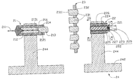
- FIG. 2 is a cross-sectional view of the optical switch assembly of FIG. 1, taken along line II-II;
- FIG. 3 is a cross-sectional view of a holder of FIG. 2, taken along line III-III
- FIG. 4 is a cross-sectional view of a holder of FIG. 2, taken along line IV-IV
- FIG. 5 is an essential optical paths diagram of the optical switch assembly of FIG. 1;
- FIG. 6 is another essential optical paths diagram of the optical switch assembly of FIG. 1;
- FIG. 7 is a perspective view of a conventional optical switch.
- an optical switch assembly in accordance with the present invention comprises an input port 21 , a switching device 23 , an output port 22 , a driving device 25 connecting with the switching device 23 , and a base 24 .
- the input port 21 comprises an input fiber 211 , a capillary 212 , a first collimating lens 213 , a first sleeve 214 and a first outer sleeve 216 .
- the input fiber 211 is fixed in the capillary 212 using epoxy resin (not labeled).
- the capillary 212 has an oblique forward end face 2121 which inclines at an angle preferably between 6 and 8 degrees.
- the first collimating lens 213 has an oblique rearward end face 2131 and an aspherical forward end face (not labeled) at opposite end thereof.
- the oblique rearward end face 2131 inclines at an angle matching that of the oblique forward end face 2121 of the capillary 212 .
- the aspherical forward end face is designed to collimate light beams emitted from the input fiber 211 into parallel light beams.
- the first collimating lens 213 is made using a molding method.
- the first inner sleeve 214 encloses the capillary 212 and the first collimating lens 213 , with the forward end face 2121 of the capillary 212 being spaced from and parallel to the rearward end face 2131 of the first collimating lens 213 .
- the first outer sleeve 216 encloses the first inner sleeve 214 .
- the switching device 23 comprises a plurality of second collimating lenses 231 fixed in a connection plate 232 .
- the connection plate 232 is oblong in shape, having a first end and a second end (not labeled).
- the second collimating lenses 231 are retained in the first end of the connection plate 232 , arranged in an arc.
- the second end connects to the driving device 25 .
- Each of the second collimating lenses 231 has an oblique rearward end face 2311 and an aspherical forward end face (not labeled).
- the oblique rearward end faces 2311 are inclined at a same angle relative to a longitudinal axis of the lens 231 , but are each oriented in a different direction.
- the second collimating lenses 231 are made using a molding method.
- the connection plate 232 is driven to rotate by the driving device 25 , whereby each of the second lenses 231 can be precisely moved into an optical path between the input and output ports 21 , 22 .
- the output port 22 comprises a plurality of output fibers 221 , a holder 222 , a second inner sleeve 224 , and a second outer sleeve 226 .
- the holder 222 comprises a core 223 , a core sleeve 225 , a support portion 229 and a ring 227 .
- the core 223 forms a plurality of longitudinally-oriented V-shaped grooves 228 in an outer surface thereof.
- Protective jackets (not labeled) are stripped from ends of the output fibers 221 , to expose a bare output optical fiber core.
- Each of the output fiber cores is fixed in a corresponding V-shaped groove 228 using epoxy resin 2200 .
- the core sleeve 225 encloses the core 223 and the output optical fiber cores therein.
- the second inner sleeve 224 encloses the core sleeve 225 .
- the second outer sleeve 226 encloses the second inner sleeve 224 .
- the support portion 229 is attached to an end (not labeled) of the core 223 using epoxy resin (not labeled).
- the ring 227 surrounds the support portion 229 . Unstripped portions of the output fibers 221 are sandwiched between the support portion 229 and the ring 227 and are fixed therein using epoxy resin 2200 .
- the base 24 comprises a substrate 242 , two supporting arms 244 extending upwardly from the substrate 242 and a bracket 245 .
- the two supporting arms 244 are for holding the input and output ports 21 , 22 .
- An opening 246 is defined through one side of the substrate 242 , for rotation of the connection plate 232 therein.
- the driving device 25 comprises a shaft (not separately labeled) which connects to the second end (not labeled) of the connection plate 232 .
- the shaft is supported in the bracket 245 and connects to a remainder of the driving device (not shown).
- one specific second collimating lens 2312 is positioned in the optical path between the input and output ports 21 , 22 .
- Light beams (not labeled) emitting from the input fiber 211 are transmitted through the first collimating lens 213 .
- the aspherical forward end face of the first collimating lens 213 transmits the light beams as parallel light beams (not labeled).
- Said parallel light beams are then refracted an angle by the oblique rearward end face 2311 , and are transmitted through the second collimating lens 2312 .
- the refracted parallel light beams are focused by the aspherical forward end face of the second collimating lens 2312 and pass through an end of a predetermined output fiber 2211 and are transmitted through the predetermined output fiber 2211 .
- another second collimating lens 2313 is positioned in the optical path between the first and second ports 21 , 22 . Since an angular orientation of the oblique rearward end face 2314 of the second collimating lens 2313 is different from that of the oblique rearward end face 2311 of the second collimating lens 2312 , the light beams are focused on an end of a different output fiber 2212 and are transmitted through the output fiber 2212 . For each different second collimating lens 231 placed in the optical path between the input and output ports 21 , 22 , the light beams are focused on a different output fiber 221 , whereby optical switching of the light path is achieved.
- the optical switch assembly of the present invention can be assembled more easily. Furthermore, the collimating lenses 213 , 231 are made by a molding method and have low manufacturing cost.
Landscapes
- Physics & Mathematics (AREA)
- General Physics & Mathematics (AREA)
- Optics & Photonics (AREA)
- Optical Couplings Of Light Guides (AREA)
- Mechanical Light Control Or Optical Switches (AREA)
Abstract
An optical switch assembly includes an input port (21), an output port (22), a switching device (23)′ and a driving device (25). The input port includes an input fiber (211), a capillary (212) retaining the input fiber and a first collimating lens (213) fixed at a front end of the capillary. The switching device locates between the input and output ports and includes a number of second collimating lenses (231) fixed in a connection plate (232). One end of the connection plate retains the second collimating lenses and a second end connects with the driving device. The output port is aligned with the input port and includes a number of output fibers (221) and a holder (222) retaining the output fibers. The driving device drives the switching device to position a second collimating lens in a light path between the input and output ports thereby effecting a switching between the input and output fibers.
Description
- 1. Field of the Invention
- The present invention relates to an optical switch assembly, and more particularly to a mechanical optical switch assembly.
- 2. Description of Prior Art
- A variety of optical switches have been developed, including mechanical optical switches, electrical optical switches and laser diode optical switches. Mechanical optical switches have better performance, and are widely used in optical systems.
- Referring to FIG. 7, U.S. Pat. No. 5,420,946 discloses a mechanical optical switch comprising an
input port 610, areflection assembly 630 and a plurality ofoutput ports 620. Theinput port 610 includes aninput fiber 611 and a gradient index (GRIN)lens 612. TheGRIN lens 612 is for collimating light beams input from theinput fiber 611. Thereflection assembly 630 includes a curved reflector 631 (which is preferably a front surface coated mirror) and amounting base 632, which defines amounting hole 633 connecting with a motor (not shown). Theoutput ports 620 each comprise anoutput fiber 621 and aGRIN lens 622. Theoutput fibers 621 and theGRIN lenses 622 are disposed in a circular fashion. They are arranged such that they are in optical alignment with a reflection point on thecurved reflector 631. The reflection point is the point where light beams transmitted frominput fiber 611 strike thereflector 631 and reflect in a predetermined direction. When aligned with light beams reflected at the reflection point, theoutput fibers 621 receive the reflected light beams. - However, the
output fibers 621 and theGRIN lenses 622 are arranged in a circular fashion, so that aligning theoutput fibers 621 and theGRIN lenses 622 with the reflection point is involved and makes assembling the switch inefficient. - Thus, it is desired to provide a reliable optical switch which can be more easily assembled.
- Accordingly, an object of the present invention is to provide an optical switch assembly which can be assembled easily and efficiently.
- Another object of the present invention is to provide an optical switch assembly which has a low manufacturing cost.
- To achieve the above objects, the present invention provides an optical switch assembly including an input port, an output port, a switching device and a driving device. The input port includes an input fiber, a capillary retaining the input fiber therein, and a first collimating lens. The first collimating lens is for collimating light beams emitted from the input fiber into parallel light beams. The switching device is located between the input port and the output port, and includes a plurality of second collimating lenses mounted in a connection plate. One end of the connection plate retains the second collimating lenses therein, and a second end of the connection plate connects to the driving device. The output port is aligned with the input port and includes a plurality of output fibers and a holder retaining the output fibers therein.
- The above and other features of the invention, including various novel details of construction and combination of parts, will now be more particularly described with reference to the accompanying drawings.
- FIG. 1 is a perspective view of an optical switch assembly in accordance with the present invention;
- FIG. 2 is a cross-sectional view of the optical switch assembly of FIG. 1, taken along line II-II;
- FIG. 3 is a cross-sectional view of a holder of FIG. 2, taken along line III-III
- FIG. 4 is a cross-sectional view of a holder of FIG. 2, taken along line IV-IV
- FIG. 5 is an essential optical paths diagram of the optical switch assembly of FIG. 1;
- FIG. 6 is another essential optical paths diagram of the optical switch assembly of FIG. 1; and
- FIG. 7 is a perspective view of a conventional optical switch.
- One preferred embodiment of an optical switch assembly according to the present invention will be described in conjunction with the drawings.
- Referring to FIG. 1, an optical switch assembly in accordance with the present invention comprises an
input port 21, aswitching device 23, anoutput port 22, adriving device 25 connecting with theswitching device 23, and abase 24. - Referring to FIG. 2, the
input port 21 comprises aninput fiber 211, a capillary 212, a firstcollimating lens 213, afirst sleeve 214 and a firstouter sleeve 216. Theinput fiber 211 is fixed in thecapillary 212 using epoxy resin (not labeled). Thecapillary 212 has an obliqueforward end face 2121 which inclines at an angle preferably between 6 and 8 degrees. The firstcollimating lens 213 has an obliquerearward end face 2131 and an aspherical forward end face (not labeled) at opposite end thereof. The obliquerearward end face 2131 inclines at an angle matching that of the obliqueforward end face 2121 of thecapillary 212. The aspherical forward end face is designed to collimate light beams emitted from theinput fiber 211 into parallel light beams. The firstcollimating lens 213 is made using a molding method. The firstinner sleeve 214 encloses the capillary 212 and the firstcollimating lens 213, with theforward end face 2121 of thecapillary 212 being spaced from and parallel to therearward end face 2131 of the firstcollimating lens 213. The firstouter sleeve 216 encloses the firstinner sleeve 214. - The
switching device 23 comprises a plurality of secondcollimating lenses 231 fixed in aconnection plate 232. Theconnection plate 232 is oblong in shape, having a first end and a second end (not labeled). The secondcollimating lenses 231 are retained in the first end of theconnection plate 232, arranged in an arc. The second end connects to thedriving device 25. Each of the secondcollimating lenses 231 has an obliquerearward end face 2311 and an aspherical forward end face (not labeled). The obliquerearward end faces 2311 are inclined at a same angle relative to a longitudinal axis of thelens 231, but are each oriented in a different direction. The secondcollimating lenses 231 are made using a molding method. In operation, theconnection plate 232 is driven to rotate by thedriving device 25, whereby each of thesecond lenses 231 can be precisely moved into an optical path between the input andoutput ports - Also referring to FIG. 2, the
output port 22 comprises a plurality ofoutput fibers 221, aholder 222, a secondinner sleeve 224, and a secondouter sleeve 226. Theholder 222 comprises acore 223, acore sleeve 225, asupport portion 229 and aring 227. - Referring to FIGS. 2 and 3, the
core 223 forms a plurality of longitudinally-oriented V-shaped grooves 228 in an outer surface thereof. Protective jackets (not labeled) are stripped from ends of theoutput fibers 221, to expose a bare output optical fiber core. Each of the output fiber cores is fixed in a corresponding V-shaped groove 228 usingepoxy resin 2200. Thecore sleeve 225 encloses thecore 223 and the output optical fiber cores therein. The secondinner sleeve 224 encloses thecore sleeve 225. The secondouter sleeve 226 encloses the secondinner sleeve 224. - Referring to FIGS. 2 and 4, the
support portion 229 is attached to an end (not labeled) of thecore 223 using epoxy resin (not labeled). Thering 227 surrounds thesupport portion 229. Unstripped portions of theoutput fibers 221 are sandwiched between thesupport portion 229 and thering 227 and are fixed therein usingepoxy resin 2200. - Referring to FIG. 1, the
base 24 comprises asubstrate 242, two supportingarms 244 extending upwardly from thesubstrate 242 and abracket 245. The two supportingarms 244 are for holding the input andoutput ports opening 246 is defined through one side of thesubstrate 242, for rotation of theconnection plate 232 therein. - The driving
device 25 comprises a shaft (not separately labeled) which connects to the second end (not labeled) of theconnection plate 232. The shaft is supported in thebracket 245 and connects to a remainder of the driving device (not shown). - Referring to FIGS. 1 and 5, one specific
second collimating lens 2312 is positioned in the optical path between the input andoutput ports input fiber 211 are transmitted through thefirst collimating lens 213. The aspherical forward end face of thefirst collimating lens 213 transmits the light beams as parallel light beams (not labeled). Said parallel light beams are then refracted an angle by the obliquerearward end face 2311, and are transmitted through thesecond collimating lens 2312. The refracted parallel light beams are focused by the aspherical forward end face of thesecond collimating lens 2312 and pass through an end of apredetermined output fiber 2211 and are transmitted through thepredetermined output fiber 2211. - Referring to FIGS. 1 and 6, another
second collimating lens 2313 is positioned in the optical path between the first andsecond ports rearward end face 2314 of thesecond collimating lens 2313 is different from that of the obliquerearward end face 2311 of thesecond collimating lens 2312, the light beams are focused on an end of adifferent output fiber 2212 and are transmitted through theoutput fiber 2212. For each different secondcollimating lens 231 placed in the optical path between the input andoutput ports different output fiber 221, whereby optical switching of the light path is achieved. - Compared with the conventional mechanical switch, the optical switch assembly of the present invention can be assembled more easily. Furthermore, the
collimating lenses - Although the present invention has been described with reference to a specific embodiment, it should be noted that the described embodiment is not necessarily exclusive and that various changes and modifications may be made to the described embodiment without departing from the scope of the invention as defined by the appended claims.
Claims (8)
1. An optical switch assembly for switching light beams from one optical input fiber between a plurality of optical output fibers comprising:
an input port, including a first collimating lens, the first collimating lens being aligned with the input fiber;
a switching device located between the input port and the output port, comprising a plurality of second collimating lenses, each of the second collimating lenses having an oblique end face;
an output port including a plurality of output fibers and a holder retaining the output fibers therein, the holder comprising a core and a core sleeve, the core sleeve enclosing the core, the output fibers being sandwiched between the core and the core sleeve, and an optical path being defined between the input and output ports; and
a driving device engaging with and selectively moving the switching device to position a selected second collimating lens in the optical path;
wherein when light beams emitted from the input fiber are transmitted through the first collimating lens, the first collimating lens transmits the light beams as parallel light beams, said parallel light beams are then refracted an angle by the oblique end face of a second collimating lens positioned in the optical path and are transmitted through the second collimating lens, the refracted parallel light beams are then focused on an end of a predetermined output fiber and are transmitted through the predetermined output fiber.
2. The optical switch assembly in accordance with claim 1 , wherein the input port further comprises a capillary, and the capillary fixes the input fiber therein.
3. The optical switch assembly in accordance with claim 1 , wherein the oblique end faces of the second collimating lenses all incline at a same angle relative to axis of the second collimating lenses, but are oriented in different directions.
4. The optical switch assembly in accordance with claim 1 , wherein the switching device further comprises a connection plate, the second collimating lenses are fixed in one end of the connection plate arranged along an arc, and the driving device connects with a second end of the connection plate.
5. The optical switch assembly in accordance with claim 1 , further comprising a base, the base comprising a substrate, two supporting arms and a bracket projecting upwardly from the substrate, wherein the supporting arms respectively hold the input and output ports therein.
6. The optical switch assembly in accordance with claim 1 , wherein the core of the holder defines a plurality of V-shaped grooves in a longitudinal direction in an outside surface thereof.
7. The optical switch assembly in accordance with claim 1 , wherein the holder further comprises a support portion and a ring, the support portion being attached to one end of the core, the plurality of output fibers being fixed around an outside surface of the support portion, and the ring enclosing the output fibers and the support portion.
8. An optical switch assembly for switching light beams from one optical input fiber between a plurality of optical output fibers comprising:
an input port, including a first collimating lens, the first collimating lens being aligned with the input fiber;
a switching device located between the input port and the output port, comprising a plurality of second collimating lenses;
an output port including a plurality of output fibers and a holder retaining the output fibers therein, the holder comprising a core and a core sleeve, the core sleeve enclosing the core, the output fibers being sandwiched between the core and the core sleeve and relatively spaced far away from one another, and an optical path being defined between the input and output ports; and
a driving device engaging with and selectively rotatably moving the switching device to position a selected second collimating lens in the optical path;
wherein when light beams emitted from the input fiber are transmitted through the first collimating lens, the first collimating lens transmits the light beams as parallel light beams, said parallel light beams are then refracted an angle by the selected second collimating lens positioned in the optical path and are transmitted through the second collimating lens, the refracted parallel light beams are then focused on an end of a predetermined output fiber and are transmitted through the predetermined output fiber; wherein
the angles defined by the second collimating lens are mutually different from one another.
Applications Claiming Priority (2)
| Application Number | Priority Date | Filing Date | Title |
|---|---|---|---|
| TW091204382U TW523104U (en) | 2002-04-04 | 2002-04-04 | Optical switch assembly |
| TW91204382 | 2002-04-04 |
Publications (1)
| Publication Number | Publication Date |
|---|---|
| US20030190117A1 true US20030190117A1 (en) | 2003-10-09 |
Family
ID=28038149
Family Applications (1)
| Application Number | Title | Priority Date | Filing Date |
|---|---|---|---|
| US10/304,574 Abandoned US20030190117A1 (en) | 2002-04-04 | 2002-11-25 | Optical switch assembly |
Country Status (2)
| Country | Link |
|---|---|
| US (1) | US20030190117A1 (en) |
| TW (1) | TW523104U (en) |
Cited By (1)
| Publication number | Priority date | Publication date | Assignee | Title |
|---|---|---|---|---|
| CN104849812A (en) * | 2014-02-18 | 2015-08-19 | 北京同洲维普科技有限公司 | Optical multichannel router |
-
2002
- 2002-04-04 TW TW091204382U patent/TW523104U/en not_active IP Right Cessation
- 2002-11-25 US US10/304,574 patent/US20030190117A1/en not_active Abandoned
Cited By (1)
| Publication number | Priority date | Publication date | Assignee | Title |
|---|---|---|---|---|
| CN104849812A (en) * | 2014-02-18 | 2015-08-19 | 北京同洲维普科技有限公司 | Optical multichannel router |
Also Published As
| Publication number | Publication date |
|---|---|
| TW523104U (en) | 2003-03-01 |
Similar Documents
| Publication | Publication Date | Title |
|---|---|---|
| US5526455A (en) | Connector including opposing lens surfaces, side surfaces, and contact surfaces for coupling optical devices | |
| JP6150809B2 (en) | Optical substrate having a plurality of staggered light redirecting mechanisms on its main surface | |
| US7387448B2 (en) | Optical component, method for connecting the same, and optical module having the optical component | |
| US6015239A (en) | Passively aligned opto-electronic coupling assembly | |
| JP4582266B2 (en) | Floodlight device and sensor | |
| JP2001242339A (en) | Optical fiber lens array | |
| JP2001051162A (en) | Optical coupling components | |
| JPH07318764A (en) | Optical semiconductor module and its connection structure | |
| US20060280421A1 (en) | Variable light attenuator | |
| JP2013200347A (en) | Optical receptacle and optical module including the same | |
| JP2004191989A (en) | Optical device and method for coupling output light from light source to optical waveguide | |
| US6687434B2 (en) | Optical element having inclined surface | |
| US11635604B2 (en) | Luminous flux collector for directing light into a light-diffusing fiber | |
| US6381386B1 (en) | V-shaped optical coupling structure | |
| JPH07134225A (en) | Sleeve integrated lens and optical coupling element module using this lens | |
| US20030202737A1 (en) | Optical switch | |
| JPH10163533A (en) | Floodlight device | |
| JP2836583B2 (en) | Optical coupling structure between light receiving element and optical fiber | |
| US20030185497A1 (en) | Optical switch | |
| CN217385905U (en) | Lens module and optical module | |
| CN2543085Y (en) | Mechanical optical switch | |
| JPH08179151A (en) | Fiber optic device | |
| US20030169963A1 (en) | Mechanical optical switch | |
| CN2543079Y (en) | Photoswitch combination | |
| WO2024116621A1 (en) | Optical connector and optical transmission module |
Legal Events
| Date | Code | Title | Description |
|---|---|---|---|
| AS | Assignment |
Owner name: HON HAI PRECISION IND. CO., LTD., TAIWAN Free format text: ASSIGNMENT OF ASSIGNORS INTEREST;ASSIGNOR:ZHOU, MINGBAO;REEL/FRAME:013533/0871 Effective date: 20021011 |
|
| STCB | Information on status: application discontinuation |
Free format text: ABANDONED -- FAILURE TO PAY ISSUE FEE |