US20020184892A1 - Fastening a CMC combustion chamber in a turbomachine using brazed tabs - Google Patents
Fastening a CMC combustion chamber in a turbomachine using brazed tabs Download PDFInfo
- Publication number
- US20020184892A1 US20020184892A1 US10/162,385 US16238502A US2002184892A1 US 20020184892 A1 US20020184892 A1 US 20020184892A1 US 16238502 A US16238502 A US 16238502A US 2002184892 A1 US2002184892 A1 US 2002184892A1
- Authority
- US
- United States
- Prior art keywords
- metal
- combustion chamber
- ring
- annular
- turbomachine according
- Prior art date
- Legal status (The legal status is an assumption and is not a legal conclusion. Google has not performed a legal analysis and makes no representation as to the accuracy of the status listed.)
- Granted
Links
- 238000002485 combustion reaction Methods 0.000 title claims abstract description 43
- 239000002184 metal Substances 0.000 claims abstract description 47
- 229910052751 metal Inorganic materials 0.000 claims abstract description 47
- 239000002131 composite material Substances 0.000 claims abstract description 38
- 210000002105 tongue Anatomy 0.000 claims abstract description 29
- 239000007769 metal material Substances 0.000 claims abstract description 11
- 239000000446 fuel Substances 0.000 claims abstract description 5
- 238000007789 sealing Methods 0.000 claims description 7
- 238000005219 brazing Methods 0.000 claims description 5
- 238000003466 welding Methods 0.000 claims description 3
- 239000000919 ceramic Substances 0.000 description 5
- 238000002347 injection Methods 0.000 description 5
- 239000007924 injection Substances 0.000 description 5
- 239000011153 ceramic matrix composite Substances 0.000 description 4
- 238000011144 upstream manufacturing Methods 0.000 description 4
- 239000000463 material Substances 0.000 description 3
- 239000007800 oxidant agent Substances 0.000 description 3
- 238000006073 displacement reaction Methods 0.000 description 2
- OKTJSMMVPCPJKN-UHFFFAOYSA-N Carbon Chemical compound [C] OKTJSMMVPCPJKN-UHFFFAOYSA-N 0.000 description 1
- 229910052799 carbon Inorganic materials 0.000 description 1
- 230000007797 corrosion Effects 0.000 description 1
- 238000005260 corrosion Methods 0.000 description 1
- 238000002788 crimping Methods 0.000 description 1
- 238000009792 diffusion process Methods 0.000 description 1
- 238000002513 implantation Methods 0.000 description 1
- 150000002739 metals Chemical class 0.000 description 1
- 230000000284 resting effect Effects 0.000 description 1
- 235000002020 sage Nutrition 0.000 description 1
Images


Classifications
-
- F—MECHANICAL ENGINEERING; LIGHTING; HEATING; WEAPONS; BLASTING
- F23—COMBUSTION APPARATUS; COMBUSTION PROCESSES
- F23R—GENERATING COMBUSTION PRODUCTS OF HIGH PRESSURE OR HIGH VELOCITY, e.g. GAS-TURBINE COMBUSTION CHAMBERS
- F23R3/00—Continuous combustion chambers using liquid or gaseous fuel
- F23R3/42—Continuous combustion chambers using liquid or gaseous fuel characterised by the arrangement or form of the flame tubes or combustion chambers
- F23R3/60—Support structures; Attaching or mounting means
-
- F—MECHANICAL ENGINEERING; LIGHTING; HEATING; WEAPONS; BLASTING
- F23—COMBUSTION APPARATUS; COMBUSTION PROCESSES
- F23R—GENERATING COMBUSTION PRODUCTS OF HIGH PRESSURE OR HIGH VELOCITY, e.g. GAS-TURBINE COMBUSTION CHAMBERS
- F23R3/00—Continuous combustion chambers using liquid or gaseous fuel
- F23R3/007—Continuous combustion chambers using liquid or gaseous fuel constructed mainly of ceramic components
-
- F—MECHANICAL ENGINEERING; LIGHTING; HEATING; WEAPONS; BLASTING
- F05—INDEXING SCHEMES RELATING TO ENGINES OR PUMPS IN VARIOUS SUBCLASSES OF CLASSES F01-F04
- F05B—INDEXING SCHEME RELATING TO WIND, SPRING, WEIGHT, INERTIA OR LIKE MOTORS, TO MACHINES OR ENGINES FOR LIQUIDS COVERED BY SUBCLASSES F03B, F03D AND F03G
- F05B2230/00—Manufacture
- F05B2230/60—Assembly methods
- F05B2230/604—Assembly methods using positioning or alignment devices for aligning or centering, e.g. pins
- F05B2230/606—Assembly methods using positioning or alignment devices for aligning or centering, e.g. pins using maintaining alignment while permitting differential dilatation
Definitions
- the present invention relates to the specific field of turbomachines and it relates more particularly to the problem posed by assembling a combustion chamber made of a composite material of the ceramic matrix composite (CMC) type in the metal chamber casings of a turbomachine.
- CMC ceramic matrix composite
- the high pressure turbine in particular its inlet nozzle (HPT nozzle), the combustion chamber, and the inner and outer shells (or casings) of said chamber are all made out of the same material, generally a metal.
- HPT nozzle inlet nozzle
- the combustion chamber in particular its inner and outer shells (or casings) of said chamber are all made out of the same material, generally a metal.
- a metal chamber turns out to be completely unsuitable from a thermal point of view and it is necessary to make use of a chamber that is based on high temperature composite materials of the CMC type.
- difficulties of implementation and materials costs mean that such materials are generally restricted to being used for the composite chamber itself, with the high pressure turbine inlet nozzle and the inner and outer shells of the chamber then still being made more conventionally out of metal materials.
- metals and composites have coefficients of thermal expansion that are very different. This gives rise to particularly awkward problems of connection with the inner and outer shells of the combustion chamber and of interface at the nozzle at the inlet to the high pressure turbine.
- the present invention mitigates those drawbacks by proposing a mounting for the combustion chamber in the casings with the ability to absorb the displacements induced by the various coefficients of expansion of those parts.
- An object of the invention is thus to propose a mounting which makes the best use of the existing characteristics of the combustion chamber.
- a turbomachine comprising inner and outer annular shells of metal material containing in a gas flow direction F: a fuel injector assembly, an annular combustion chamber of composite material and having a longitudinal axis, and an annular nozzle of metal material and forming the fixed-blade inlet stage of a high pressure turbine, wherein said composite material combustion chamber is held in position between said inner and outer metal annular shells by a plurality of flexible tongues, first ends of said tongues being interconnected by a metal ring fixed securely to each of said inner and outer metal annular shells by first fixing means, and second ends being fixed by second fixing means to a ring of composite material fixed securely to said composite material combustion chamber, the flexibility of said fixing tongues allowing expansion to take place freely in a radial direction at high temperatures between said composite material combustion chamber and said metal annular shells.
- the first and second fixing means are preferably constituted by a plurality of bolts.
- each of said metal annular shells is made up of two portions
- said metal ring interconnecting said first ends of said metal fixing tongues is mounted between connecting flanges of said two portions.
- said metal ring can be fixed directly to said annular shell by fixing means.
- said first ends of the fixing tongues can either be fixed by brazing to said metal ring, or else they can be formed integrally with said metal ring.
- said composite ring is brazed onto a downstream end of the combustion chamber.
- the composite ring is sewn onto the downstream end.
- the composite ring is implanted on the downstream end.
- Said composite ring includes a determined portion forming a bearing plane for a sealing gasket (advantageously of the circular “spring blade” gasket type) ensuring that the stream of gas between said combustion chamber and said nozzle is sealed.
- Said determined portion is preferably an end portion of said composite ring.
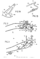
- FIG. 1 is a diagrammatic axial half-section of a central zone of a turbomachine in a first embodiment of the invention
- FIG. 2 is a view on a larger scale showing a portion of FIG. 1 in an alternative connection configuration
- FIG. 3 is an enlarged view of another portion of FIG. 1 in an alternative connection configuration.
- FIG. 1 is an axial half-section view of a central portion of a turbojet or a turboprop (with the term “turbomachine” being used generically in the description below) and comprising:
- an outer annular shell made up of two portions 12 a and 12 b of metal material, having a longitudinal axis 10 ;
- an inner annular shell (or inner casing) that is coaxial therewith and likewise comprises two portions 14 a and 14 b , also made of metal material;
- annular space 16 extending between the two shells 12 a , 12 b and 14 a , 14 b for receiving compressed oxidizer, generally air, coming from an upstream compressor (not shown) of the turbomachine via an annular diffuser duct 18 defining a general flow F of gas.
- this space 16 comprises firstly an injection assembly formed by a plurality of injection systems 20 that are regularly distributed around the duct 18 , each comprising a fuel injection nozzle 22 fixed to an upstream portion 12 a of the outer annular shell 12 (in order to simplify the drawings, the mixer and the deflector associated with each injection nozzle are omitted), followed by a combustion chamber 24 of high temperature composite material, e.g. of the CMC type or of some other type (e.g.
- the nozzle is fixed to the downstream portion 14 b of the inner annular shell of the turbomachine by first removable fixing means preferably constituted by a plurality of bolts 50 , while resting on support means 49 secured to the outer annular shell of the turbomachine.
- Through orifices 54 , 56 formed in the outer and inner metal platforms 46 and 48 of the nozzle 42 are also provided to cool the fixed blades 46 of this nozzle at the inlet to the rotor of the high pressure turbine using compressed oxidizer available at the outlet from the diffusion duct 18 and flowing in two flows F 1 and F 2 on either side of the combustion chamber 24 .
- the combustion chamber 24 has a coefficient of thermal expansion that is very different from that of the other parts forming the turbomachine, since they are made of metal.
- the combustion chamber 24 is held securely in position between the inner and outer annular shells by a plurality of flexible tongues 58 , 60 regularly distributed around the combustion chamber.
- a first fraction of these fixing tongues (see the tongues referenced 58 ) is mounted between the outer annular shell 12 a , 12 b and the outer side wall 26 of the combustion chamber, while a second fraction (like the tongues 60 ) is mounted between the inner annular shell 14 a , 14 b and the inner side wall 28 of the combustion chamber.
- Each flexible fixing tongue of metal material can be substantially triangular in shape as shown in FIG. 1A or it can be constituted by a single blade (of optionally constant width), and it is welded or brazed at a first end 62 ; 64 to a metal ring 66 a , 66 b fixed securely by first fixing means 52 ; 68 to one or the other of the inner and outer metal annular shells 12 , 15 (depending on where it is located) and intended to make it easier both to hold these tongues and to seal the annular gap 16 .
- these tongues and the metal ring together form a single one-piece metal part.
- each tongue is securely fixed via second fixing means 74 , 76 to a ceramic composite ring 78 a ; 78 b brazed onto a downstream end 88 ; 90 of the outer and inner side walls 26 and 28 of the ceramic composite material combustion chamber.
- This brazing can be replaced or even reinforced by stitching.
- the connection between the chamber walls and the rings can also be made entirely by implantation (connection of the type known by the term “pin'sage”).
- the number of tongues can be a number that is equal to the number of injection nozzles or to a multiple of said number.
- FIG. 1 shows a first embodiment of the invention in which the second ends of the tongues 70 , 72 are respectively fixed on the outer and inner ceramic composite rings 78 a and 78 b by simple bolting (but crimping could also be envisaged, as shown in fragmentary view in FIG. 1B).
- the metal ring 66 a , 66 b interconnecting the first ends 62 , 64 of the tongues is preferably clamped between the existing connection flanges between the upstream and downstream portions of the inner and outer annular shells 14 , 12 and held securely by the first fixing means 52 , 68 which are preferably likewise of the bolt type.
- ceramic composite material washers 74 a ; 76 a are provided to enable the flat headed screws of the bolts forming the second fixing means 74 ; 76 to be “embedded”.
- the metal ring 66 a interconnecting the first ends 62 of the fixing tongues 58 of the outer side wall 26 of the combustion chamber by welding (or brazing) is no longer mounted between flanges but is itself welded (or brazed) to a centered keying element 106 secured to the outer annular shell 12 .
- the metal ring 66 b interconnecting the first ends 64 of the fixing tongues 60 of the inner side wall 28 of the combustion chamber by welding (or brazing) is no longer mounted between flanges but is merely fixed directly to the inner annular shell 14 by fixing means 108 , e.g. of the bolt type.
- the stream of gas between the combustion chamber 24 and the nozzle 42 is sealed by a circular “spring blade” gasket 80 , 82 mounted in a groove 84 , 86 of each of the outer and inner platforms 46 and 48 of the nozzle and which bear directly against a portion of the ceramic composite ring 78 a ; 78 b forming a bearing plane for said circular sealing gasket.
- the portion can be an end portion of the ring.
- the gasket is pressed against said end portion of the composite ring or any other portion by means of a resilient element 92 , 94 fixed to the nozzle.
- the gas flows between the combustion chamber and the turbine are sealed firstly by an omega type circular sealing gasket 96 mounted in a circular groove 98 of a flange of the inner annular shell 14 in direct contact with the inner circular platform 48 of the nozzle, and secondly by another circular spring blade gasket 100 mounted in a circular groove 102 of the outer circular platform of the nozzle 46 and having one end in direct contact with a circular projection 104 on the downstream portion 12 b of the outer annular shell.
- the flexibility of the fixing tongues makes it possible to accommodate the thermal expansion difference that appears at high temperatures between the composite material combustion chamber and the metal annular shells, while continuing to hold and position the combustion chamber.
Landscapes
- Engineering & Computer Science (AREA)
- Chemical & Material Sciences (AREA)
- Combustion & Propulsion (AREA)
- Mechanical Engineering (AREA)
- General Engineering & Computer Science (AREA)
- Ceramic Engineering (AREA)
- Turbine Rotor Nozzle Sealing (AREA)
Abstract
Description
- The present invention relates to the specific field of turbomachines and it relates more particularly to the problem posed by assembling a combustion chamber made of a composite material of the ceramic matrix composite (CMC) type in the metal chamber casings of a turbomachine.
- Conventionally, in a turbojet or a turboprop, the high pressure turbine, in particular its inlet nozzle (HPT nozzle), the combustion chamber, and the inner and outer shells (or casings) of said chamber are all made out of the same material, generally a metal. Nevertheless, under certain particular conditions of use implementing particularly high combustion temperatures, a metal chamber turns out to be completely unsuitable from a thermal point of view and it is necessary to make use of a chamber that is based on high temperature composite materials of the CMC type. However, difficulties of implementation and materials costs mean that such materials are generally restricted to being used for the composite chamber itself, with the high pressure turbine inlet nozzle and the inner and outer shells of the chamber then still being made more conventionally out of metal materials. Unfortunately, metals and composites have coefficients of thermal expansion that are very different. This gives rise to particularly awkward problems of connection with the inner and outer shells of the combustion chamber and of interface at the nozzle at the inlet to the high pressure turbine.
- The present invention mitigates those drawbacks by proposing a mounting for the combustion chamber in the casings with the ability to absorb the displacements induced by the various coefficients of expansion of those parts. An object of the invention is thus to propose a mounting which makes the best use of the existing characteristics of the combustion chamber.
- These objects are achieved by a turbomachine comprising inner and outer annular shells of metal material containing in a gas flow direction F: a fuel injector assembly, an annular combustion chamber of composite material and having a longitudinal axis, and an annular nozzle of metal material and forming the fixed-blade inlet stage of a high pressure turbine, wherein said composite material combustion chamber is held in position between said inner and outer metal annular shells by a plurality of flexible tongues, first ends of said tongues being interconnected by a metal ring fixed securely to each of said inner and outer metal annular shells by first fixing means, and second ends being fixed by second fixing means to a ring of composite material fixed securely to said composite material combustion chamber, the flexibility of said fixing tongues allowing expansion to take place freely in a radial direction at high temperatures between said composite material combustion chamber and said metal annular shells.
- With this particular structure for the fixed connection, the various kinds of wear due to contact corrosion in prior art systems can be avoided. The use of a ring made of composite material to provide sealing of the stream also makes it possible to keep the initial structure of the chamber intact. In addition, the presence of flexible metal tongues replacing the traditional flanges gives rise to a saving in mass that is particularly appreciable. In addition to being flexible, these tongues make it easy to accommodate the expansion difference that appears at high temperatures between metal parts and composite parts (by accommodating the displacements due to expansion) while still ensuring that the combustion chamber is properly held and well centered in the annular shell.
- The first and second fixing means are preferably constituted by a plurality of bolts.
- In an advantageous embodiment in which each of said metal annular shells is made up of two portions, said metal ring interconnecting said first ends of said metal fixing tongues is mounted between connecting flanges of said two portions. In an alternative embodiment, said metal ring can be fixed directly to said annular shell by fixing means.
- Depending on the intended embodiment, said first ends of the fixing tongues can either be fixed by brazing to said metal ring, or else they can be formed integrally with said metal ring.
- In a preferred embodiment, said composite ring is brazed onto a downstream end of the combustion chamber. In an alternative embodiment, the composite ring is sewn onto the downstream end. In another embodiment, the composite ring is implanted on the downstream end.
- Said composite ring includes a determined portion forming a bearing plane for a sealing gasket (advantageously of the circular “spring blade” gasket type) ensuring that the stream of gas between said combustion chamber and said nozzle is sealed. Said determined portion is preferably an end portion of said composite ring.
- The characteristics and advantages of the present invention appear better from the following description made by way of non-limiting indication and with reference to the accompanying drawings, in which:
- FIG. 1 is a diagrammatic axial half-section of a central zone of a turbomachine in a first embodiment of the invention;
- FIG. 2 is a view on a larger scale showing a portion of FIG. 1 in an alternative connection configuration; and
- FIG. 3 is an enlarged view of another portion of FIG. 1 in an alternative connection configuration.
- FIG. 1 is an axial half-section view of a central portion of a turbojet or a turboprop (with the term “turbomachine” being used generically in the description below) and comprising:
- an outer annular shell (or outer casing) made up of two
portions longitudinal axis 10; - an inner annular shell (or inner casing) that is coaxial therewith and likewise comprises two
portions - an
annular space 16 extending between the twoshells annular diffuser duct 18 defining a general flow F of gas. - In the gas flow direction, this
space 16 comprises firstly an injection assembly formed by a plurality ofinjection systems 20 that are regularly distributed around theduct 18, each comprising afuel injection nozzle 22 fixed to anupstream portion 12 a of the outer annular shell 12 (in order to simplify the drawings, the mixer and the deflector associated with each injection nozzle are omitted), followed by acombustion chamber 24 of high temperature composite material, e.g. of the CMC type or of some other type (e.g. carbon), formed by an outer axially-extending side wall 26 and an inner axially-extendingside wall 28, both disposed coaxially about theaxis 10, and a transversely-extendingend wall 30 of said combustion chamber and which hasmargins upstream ends said side walls 26, 28, thischamber end wall 30 being provided with throughorifices 40 to enable fuel to be injected together with a fraction of the oxidizer into thecombustion chamber 24, and finally anannular nozzle 42 of metal material forming an inlet stage of a high pressure turbine (not shown) and conventionally comprising a plurality offixed blades 44 mounted between an outercircular platform 46 and an innercircular platform 48. - The nozzle is fixed to the
downstream portion 14 b of the inner annular shell of the turbomachine by first removable fixing means preferably constituted by a plurality ofbolts 50, while resting on support means 49 secured to the outer annular shell of the turbomachine. - Through
orifices inner metal platforms nozzle 42 are also provided to cool thefixed blades 46 of this nozzle at the inlet to the rotor of the high pressure turbine using compressed oxidizer available at the outlet from thediffusion duct 18 and flowing in two flows F1 and F2 on either side of thecombustion chamber 24. - The
combustion chamber 24 has a coefficient of thermal expansion that is very different from that of the other parts forming the turbomachine, since they are made of metal. In accordance with the invention, thecombustion chamber 24 is held securely in position between the inner and outer annular shells by a plurality offlexible tongues annular shell annular shell inner side wall 28 of the combustion chamber. - Each flexible fixing tongue of metal material can be substantially triangular in shape as shown in FIG. 1A or it can be constituted by a single blade (of optionally constant width), and it is welded or brazed at a
first end 62; 64 to ametal ring first fixing means 52; 68 to one or the other of the inner and outer metal annular shells 12, 15 (depending on where it is located) and intended to make it easier both to hold these tongues and to seal theannular gap 16. In a preferred embodiment, these tongues and the metal ring together form a single one-piece metal part. At asecond end 70; 72, each tongue is securely fixed via second fixing means 74, 76 to a ceramiccomposite ring 78 a; 78 b brazed onto adownstream end 88; 90 of the outer andinner side walls 26 and 28 of the ceramic composite material combustion chamber. This brazing can be replaced or even reinforced by stitching. The connection between the chamber walls and the rings can also be made entirely by implantation (connection of the type known by the term “pin'sage”). By way of example, the number of tongues can be a number that is equal to the number of injection nozzles or to a multiple of said number. - FIG. 1 shows a first embodiment of the invention in which the second ends of the
tongues ceramic composite rings metal ring first ends annular shells 14, 12 and held securely by the first fixing means 52, 68 which are preferably likewise of the bolt type. It should be observed that ceramiccomposite material washers 74 a; 76 a are provided to enable the flat headed screws of the bolts forming the second fixing means 74; 76 to be “embedded”. - In the variant shown in FIG. 2, the
metal ring 66 a interconnecting thefirst ends 62 of thefixing tongues 58 of the outer side wall 26 of the combustion chamber by welding (or brazing) is no longer mounted between flanges but is itself welded (or brazed) to acentered keying element 106 secured to the outer annular shell 12. - In another variant shown in FIG. 3, the
metal ring 66 b interconnecting thefirst ends 64 of thefixing tongues 60 of theinner side wall 28 of the combustion chamber by welding (or brazing) is no longer mounted between flanges but is merely fixed directly to the innerannular shell 14 by fixing means 108, e.g. of the bolt type. - The stream of gas between the
combustion chamber 24 and thenozzle 42 is sealed by a circular “spring blade”gasket groove inner platforms composite ring 78 a; 78 b forming a bearing plane for said circular sealing gasket. The portion can be an end portion of the ring. The gasket is pressed against said end portion of the composite ring or any other portion by means of aresilient element combustion chamber 24 and thenozzle 42. - The gas flows between the combustion chamber and the turbine are sealed firstly by an omega type
circular sealing gasket 96 mounted in acircular groove 98 of a flange of the innerannular shell 14 in direct contact with the innercircular platform 48 of the nozzle, and secondly by another circularspring blade gasket 100 mounted in acircular groove 102 of the outer circular platform of thenozzle 46 and having one end in direct contact with acircular projection 104 on thedownstream portion 12 b of the outer annular shell. - In all of the above-described configurations, the flexibility of the fixing tongues makes it possible to accommodate the thermal expansion difference that appears at high temperatures between the composite material combustion chamber and the metal annular shells, while continuing to hold and position the combustion chamber.
Claims (12)
Applications Claiming Priority (2)
| Application Number | Priority Date | Filing Date | Title |
|---|---|---|---|
| FR0107363A FR2825783B1 (en) | 2001-06-06 | 2001-06-06 | HANGING OF CMC COMBUSTION CHAMBER OF TURBOMACHINE BY BRAZED LEGS |
| FR0107363 | 2001-06-06 |
Publications (2)
| Publication Number | Publication Date |
|---|---|
| US20020184892A1 true US20020184892A1 (en) | 2002-12-12 |
| US6708495B2 US6708495B2 (en) | 2004-03-23 |
Family
ID=8863987
Family Applications (1)
| Application Number | Title | Priority Date | Filing Date |
|---|---|---|---|
| US10/162,385 Expired - Lifetime US6708495B2 (en) | 2001-06-06 | 2002-06-05 | Fastening a CMC combustion chamber in a turbomachine using brazed tabs |
Country Status (5)
| Country | Link |
|---|---|
| US (1) | US6708495B2 (en) |
| EP (1) | EP1265034B1 (en) |
| JP (1) | JP3907529B2 (en) |
| DE (1) | DE60229465D1 (en) |
| FR (1) | FR2825783B1 (en) |
Cited By (46)
| Publication number | Priority date | Publication date | Assignee | Title |
|---|---|---|---|---|
| US20030046940A1 (en) * | 2001-09-12 | 2003-03-13 | Kawasaki Jukogyo Kabushiki Kaisha | Seal structure for combustor liner |
| GB2400650A (en) * | 2002-06-13 | 2004-10-20 | Snecma Propulsion Solide | A combustion chamber ring and a combustion chamber. |
| GB2415496A (en) * | 2004-06-17 | 2005-12-28 | Snecma Moteurs | A Gas Turbine Combustion Chamber Made of Ceramic which is Supported in a Metal Casing by Brazed Linkages |
| EP1439350A3 (en) * | 2003-01-14 | 2006-01-18 | General Electric Company | Support assembly for a gas turbine engine combustor |
| US20060010879A1 (en) * | 2004-06-17 | 2006-01-19 | Snecma Moteurs | Mounting a turbine nozzle on a combustion chamber having CMC walls in a gas turbine |
| EP1731715A1 (en) * | 2005-06-10 | 2006-12-13 | Siemens Aktiengesellschaft | Transition between a combustion chamber and a turbine |
| US20090071167A1 (en) * | 2005-12-14 | 2009-03-19 | Alstom Technology Ltd. | Turbomachine, especially gas turbine |
| US20090100838A1 (en) * | 2007-10-23 | 2009-04-23 | Rolls-Royce Plc | Wall element for use in combustion apparatus |
| US20090173416A1 (en) * | 2008-01-08 | 2009-07-09 | Rolls-Royce Plc | Gas heater |
| US20090193813A1 (en) * | 2008-02-01 | 2009-08-06 | Rolls-Royce Plc | Combustion apparatus |
| US20090229273A1 (en) * | 2008-02-11 | 2009-09-17 | Rolls-Royce Plc | Combustor wall apparatus with parts joined by mechanical fasteners |
| EP2107307A1 (en) * | 2008-04-03 | 2009-10-07 | Snecma Propulsion Solide | Gas turbine combustor with sectorised internal and external walls |
| US20090293492A1 (en) * | 2008-06-02 | 2009-12-03 | Rolls-Royce Plc. | Combustion apparatus |
| US20100095678A1 (en) * | 2008-10-22 | 2010-04-22 | Eduardo Hawie | Heat Shield Sealing for Gas Turbine Engine Combustor |
| US20110020118A1 (en) * | 2009-07-21 | 2011-01-27 | Honeywell International Inc. | Turbine nozzle assembly including radially-compliant spring member for gas turbine engine |
| EP1923578A3 (en) * | 2006-11-17 | 2011-07-27 | Connie E. Bird | CMC fastening system |
| US20120073259A1 (en) * | 2009-04-07 | 2012-03-29 | Snecma | Turbomachine having an annular combustion chamber |
| US20120242045A1 (en) * | 2009-09-28 | 2012-09-27 | David Ronald Adair | Combustor interface sealing arrangement |
| RU2497251C1 (en) * | 2012-03-30 | 2013-10-27 | Открытое акционерное общество "Уфимское научно-производственное предприятие "Молния" (ОАО УНПП "Молния") | Ignition plug for combustion chambers of power and propulsion plants |
| US20140030077A1 (en) * | 2012-07-30 | 2014-01-30 | Alstom Technology Ltd | Stationary gas turbine arrangement and method for performing maintenance work |
| US20140109592A1 (en) * | 2012-10-22 | 2014-04-24 | United Technologies Corporation | Leaf spring hanger for exhaust duct liner |
| US20140223919A1 (en) * | 2013-02-14 | 2014-08-14 | United Technologies Corporation | Flexible liner hanger |
| US20140311151A1 (en) * | 2011-11-16 | 2014-10-23 | Mitsubishi Hitachi Power Systems, Ltd. | Gas turbine combustor |
| US20160153659A1 (en) * | 2013-07-19 | 2016-06-02 | United Technologies Corporation | Gas turbine engine ceramic component assembly and bonding material |
| US20160161121A1 (en) * | 2013-07-16 | 2016-06-09 | United Technologies Corporation | Gas turbine engine with ceramic panel |
| US9435266B2 (en) | 2013-03-15 | 2016-09-06 | Rolls-Royce North American Technologies, Inc. | Seals for a gas turbine engine |
| US20170059159A1 (en) * | 2015-08-25 | 2017-03-02 | Rolls-Royce Corporation | Cmc combustor shell with integral chutes |
| EP3159505A1 (en) * | 2015-10-20 | 2017-04-26 | MTU Aero Engines GmbH | Module for a gas turbine |
| US9664389B2 (en) | 2013-12-12 | 2017-05-30 | United Technologies Corporation | Attachment assembly for protective panel |
| US20170292704A1 (en) * | 2016-04-12 | 2017-10-12 | United Technologies Corporation | Heat shield with axial retention lock |
| US20170307221A1 (en) * | 2016-04-22 | 2017-10-26 | Rolls-Royce Plc | Combustion chamber |
| US20180016927A1 (en) * | 2016-07-12 | 2018-01-18 | General Electric Company | Sealing system for sealing against a non-cylindrical surface |
| RU182925U1 (en) * | 2018-04-16 | 2018-09-06 | Акционерное общество "Уфимское научно-производственное предприятие "Молния" | SURFACE IGNITION CANDLE FOR CAPACITIVE IGNITION SYSTEM |
| US10088161B2 (en) | 2013-12-19 | 2018-10-02 | United Technologies Corporation | Gas turbine engine wall assembly with circumferential rail stud architecture |
| US10234140B2 (en) | 2013-12-31 | 2019-03-19 | United Technologies Corporation | Gas turbine engine wall assembly with enhanced flow architecture |
| US10240790B2 (en) | 2013-11-04 | 2019-03-26 | United Technologies Corporation | Turbine engine combustor heat shield with multi-height rails |
| US10669939B2 (en) | 2016-10-26 | 2020-06-02 | Raytheon Technologies Corporation | Combustor seal for a gas turbine engine combustor |
| US10670269B2 (en) | 2016-10-26 | 2020-06-02 | Raytheon Technologies Corporation | Cast combustor liner panel gating feature for a gas turbine engine combustor |
| US10808937B2 (en) | 2013-11-04 | 2020-10-20 | Raytheon Technologies Corporation | Gas turbine engine wall assembly with offset rail |
| US10823410B2 (en) | 2016-10-26 | 2020-11-03 | Raytheon Technologies Corporation | Cast combustor liner panel radius for gas turbine engine combustor |
| US10830448B2 (en) | 2016-10-26 | 2020-11-10 | Raytheon Technologies Corporation | Combustor liner panel with a multiple of heat transfer augmentors for a gas turbine engine combustor |
| US10837638B2 (en) | 2016-04-12 | 2020-11-17 | Raytheon Technologies Corporation | Heat shield with axial retention lock |
| US10935243B2 (en) | 2016-11-30 | 2021-03-02 | Raytheon Technologies Corporation | Regulated combustor liner panel for a gas turbine engine combustor |
| US11248797B2 (en) * | 2018-11-02 | 2022-02-15 | Chromalloy Gas Turbine Llc | Axial stop configuration for a combustion liner |
| US11377970B2 (en) | 2018-11-02 | 2022-07-05 | Chromalloy Gas Turbine Llc | System and method for providing compressed air to a gas turbine combustor |
| CN117212835A (en) * | 2023-06-27 | 2023-12-12 | 中国航发湖南动力机械研究所 | A non-metal composite combustion chamber flame tube based on elastic connection structure |
Families Citing this family (24)
| Publication number | Priority date | Publication date | Assignee | Title |
|---|---|---|---|---|
| US10839321B2 (en) * | 1997-01-06 | 2020-11-17 | Jeffrey Eder | Automated data storage system |
| EP1312865A1 (en) * | 2001-11-15 | 2003-05-21 | Siemens Aktiengesellschaft | Gas turbine annular combustion chamber |
| US7047722B2 (en) * | 2002-10-02 | 2006-05-23 | Claudio Filippone | Small scale hybrid engine (SSHE) utilizing fossil fuels |
| FR2855249B1 (en) * | 2003-05-20 | 2005-07-08 | Snecma Moteurs | COMBUSTION CHAMBER HAVING A FLEXIBLE CONNECTION BETWEEN A BOTTOM BED AND A BEDROOM |
| FR2871845B1 (en) * | 2004-06-17 | 2009-06-26 | Snecma Moteurs Sa | GAS TURBINE COMBUSTION CHAMBER ASSEMBLY WITH INTEGRATED HIGH PRESSURE TURBINE DISPENSER |
| US7197877B2 (en) * | 2004-08-04 | 2007-04-03 | Siemens Power Generation, Inc. | Support system for a pilot nozzle of a turbine engine |
| US7647779B2 (en) * | 2005-04-27 | 2010-01-19 | United Technologies Corporation | Compliant metal support for ceramic combustor liner in a gas turbine engine |
| FR2892181B1 (en) * | 2005-10-18 | 2008-02-01 | Snecma Sa | FIXING A COMBUSTION CHAMBER WITHIN ITS CARTER |
| US7578134B2 (en) * | 2006-01-11 | 2009-08-25 | General Electric Company | Methods and apparatus for assembling gas turbine engines |
| US8863528B2 (en) * | 2006-07-27 | 2014-10-21 | United Technologies Corporation | Ceramic combustor can for a gas turbine engine |
| US8141370B2 (en) * | 2006-08-08 | 2012-03-27 | General Electric Company | Methods and apparatus for radially compliant component mounting |
| US20090067917A1 (en) * | 2007-09-07 | 2009-03-12 | The Boeing Company | Bipod Flexure Ring |
| US8726675B2 (en) * | 2007-09-07 | 2014-05-20 | The Boeing Company | Scalloped flexure ring |
| FR2929690B1 (en) * | 2008-04-03 | 2012-08-17 | Snecma Propulsion Solide | COMBUSTION CHAMBER SECTORIZED IN CMC FOR GAS TURBINE |
| FR2935753B1 (en) * | 2008-09-08 | 2011-07-01 | Snecma Propulsion Solide | FASTENING, FASTENING CONNECTIONS FOR MOUNTING CMC PIECES |
| US8322983B2 (en) * | 2008-09-11 | 2012-12-04 | Siemens Energy, Inc. | Ceramic matrix composite structure |
| FR2976021B1 (en) * | 2011-05-30 | 2014-03-28 | Snecma | TURBOMACHINE WITH ANNULAR COMBUSTION CHAMBER |
| US9335051B2 (en) * | 2011-07-13 | 2016-05-10 | United Technologies Corporation | Ceramic matrix composite combustor vane ring assembly |
| WO2014149108A1 (en) | 2013-03-15 | 2014-09-25 | Graves Charles B | Shell and tiled liner arrangement for a combustor |
| FR3010774B1 (en) * | 2013-09-16 | 2018-01-05 | Safran Aircraft Engines | TURBOMACHINE WITH COMBUSTION CHAMBER MAINTAINED BY A METAL FIXING CROWN |
| CN105298684B (en) * | 2015-09-18 | 2017-11-03 | 中国航空工业集团公司沈阳发动机设计研究所 | A kind of aero-engine tail bone attachment structure |
| EP3385506B1 (en) * | 2017-04-07 | 2019-10-30 | MTU Aero Engines GmbH | Sealing arrangement for a gas turbine engine |
| US10385731B2 (en) * | 2017-06-12 | 2019-08-20 | General Electric Company | CTE matching hanger support for CMC structures |
| FR3111964B1 (en) | 2020-06-26 | 2023-03-17 | Safran Helicopter Engines | Assembly of a combustion chamber part by covering with another part |
Citations (1)
| Publication number | Priority date | Publication date | Assignee | Title |
|---|---|---|---|---|
| US6397603B1 (en) * | 2000-05-05 | 2002-06-04 | The United States Of America As Represented By The Secretary Of The Air Force | Conbustor having a ceramic matrix composite liner |
Family Cites Families (9)
| Publication number | Priority date | Publication date | Assignee | Title |
|---|---|---|---|---|
| FR316233A (en) | ||||
| US2509503A (en) * | 1946-02-12 | 1950-05-30 | Lucas Ltd Joseph | Combustion chamber for prime movers |
| US2509593A (en) | 1947-05-21 | 1950-05-30 | Rca Corp | Humidity compensated oscillator |
| JPS52158202U (en) * | 1976-05-27 | 1977-12-01 | ||
| GB1570875A (en) * | 1977-03-16 | 1980-07-09 | Lucas Industries Ltd | Combustion equipment |
| CH633351A5 (en) * | 1978-11-09 | 1982-11-30 | Sulzer Ag | RESISTANT SEALING OF A RING COMBUSTION CHAMBER FOR A GAS TURBINE. |
| FR2623249A1 (en) * | 1987-11-12 | 1989-05-19 | Snecma | ASSEMBLY CONSISTING OF TWO PIECES OF MATERIALS HAVING DIFFERENT EXPANSION COEFFICIENTS, CONNECTED THEREBY AND METHOD OF ASSEMBLY |
| JP2597800B2 (en) * | 1992-06-12 | 1997-04-09 | ゼネラル・エレクトリック・カンパニイ | Gas turbine engine combustor |
| DE19745683A1 (en) * | 1997-10-16 | 1999-04-22 | Bmw Rolls Royce Gmbh | Suspension of an annular gas turbine combustion chamber |
-
2001
- 2001-06-06 FR FR0107363A patent/FR2825783B1/en not_active Expired - Fee Related
-
2002
- 2002-06-03 JP JP2002161064A patent/JP3907529B2/en not_active Expired - Fee Related
- 2002-06-04 DE DE60229465T patent/DE60229465D1/en not_active Expired - Lifetime
- 2002-06-04 EP EP02291363A patent/EP1265034B1/en not_active Expired - Lifetime
- 2002-06-05 US US10/162,385 patent/US6708495B2/en not_active Expired - Lifetime
Patent Citations (1)
| Publication number | Priority date | Publication date | Assignee | Title |
|---|---|---|---|---|
| US6397603B1 (en) * | 2000-05-05 | 2002-06-04 | The United States Of America As Represented By The Secretary Of The Air Force | Conbustor having a ceramic matrix composite liner |
Cited By (76)
| Publication number | Priority date | Publication date | Assignee | Title |
|---|---|---|---|---|
| US20030046940A1 (en) * | 2001-09-12 | 2003-03-13 | Kawasaki Jukogyo Kabushiki Kaisha | Seal structure for combustor liner |
| US6658853B2 (en) * | 2001-09-12 | 2003-12-09 | Kawasaki Jukogyo Kabushiki Kaisha | Seal structure for combustor liner |
| US6988369B2 (en) | 2002-06-13 | 2006-01-24 | Snecma Propulsion Solide | Combustion chamber sealing ring, and a combustion chamber including such a ring |
| GB2400650A (en) * | 2002-06-13 | 2004-10-20 | Snecma Propulsion Solide | A combustion chamber ring and a combustion chamber. |
| GB2400650B (en) * | 2002-06-13 | 2006-06-28 | Snecma Propulsion Solide | A combustion chamber sealing ring and a combustion chamber including such a ring |
| EP1439350A3 (en) * | 2003-01-14 | 2006-01-18 | General Electric Company | Support assembly for a gas turbine engine combustor |
| US20060010879A1 (en) * | 2004-06-17 | 2006-01-19 | Snecma Moteurs | Mounting a turbine nozzle on a combustion chamber having CMC walls in a gas turbine |
| GB2415496B (en) * | 2004-06-17 | 2008-11-26 | Snecma Moteurs | A gas turbine combustion chamber made of CMC and supported in a metal casing by CMC linking members |
| US20060032235A1 (en) * | 2004-06-17 | 2006-02-16 | Snecma Moteurs | Gas turbine combustion chamber made of CMC and supported in a metal casing by CMC linking members |
| GB2415496A (en) * | 2004-06-17 | 2005-12-28 | Snecma Moteurs | A Gas Turbine Combustion Chamber Made of Ceramic which is Supported in a Metal Casing by Brazed Linkages |
| US7234306B2 (en) | 2004-06-17 | 2007-06-26 | Snecma | Gas turbine combustion chamber made of CMC and supported in a metal casing by CMC linking members |
| US7249462B2 (en) | 2004-06-17 | 2007-07-31 | Snecma | Mounting a turbine nozzle on a combustion chamber having CMC walls in a gas turbine |
| EP1731715A1 (en) * | 2005-06-10 | 2006-12-13 | Siemens Aktiengesellschaft | Transition between a combustion chamber and a turbine |
| US20090071167A1 (en) * | 2005-12-14 | 2009-03-19 | Alstom Technology Ltd. | Turbomachine, especially gas turbine |
| US8555655B2 (en) * | 2005-12-14 | 2013-10-15 | Alstom Technology Ltd | Turbomachine, especially gas turbine |
| EP1923578A3 (en) * | 2006-11-17 | 2011-07-27 | Connie E. Bird | CMC fastening system |
| US20090100838A1 (en) * | 2007-10-23 | 2009-04-23 | Rolls-Royce Plc | Wall element for use in combustion apparatus |
| US8113004B2 (en) | 2007-10-23 | 2012-02-14 | Rolls-Royce, Plc | Wall element for use in combustion apparatus |
| US20090173416A1 (en) * | 2008-01-08 | 2009-07-09 | Rolls-Royce Plc | Gas heater |
| US8617460B2 (en) | 2008-01-08 | 2013-12-31 | Rolls-Royce Plc | Gas heater |
| US20090193813A1 (en) * | 2008-02-01 | 2009-08-06 | Rolls-Royce Plc | Combustion apparatus |
| US8256224B2 (en) | 2008-02-01 | 2012-09-04 | Rolls-Royce Plc | Combustion apparatus |
| US20090229273A1 (en) * | 2008-02-11 | 2009-09-17 | Rolls-Royce Plc | Combustor wall apparatus with parts joined by mechanical fasteners |
| US8408010B2 (en) | 2008-02-11 | 2013-04-02 | Rolls-Royce Plc | Combustor wall apparatus with parts joined by mechanical fasteners |
| FR2929689A1 (en) * | 2008-04-03 | 2009-10-09 | Snecma Propulsion Solide Sa | GAS TURBINE COMBUSTION CHAMBER WITH SECTORIZED INTERNAL AND EXTERNAL WALLS |
| EP2107307A1 (en) * | 2008-04-03 | 2009-10-07 | Snecma Propulsion Solide | Gas turbine combustor with sectorised internal and external walls |
| US8146372B2 (en) | 2008-04-03 | 2012-04-03 | Snecma Propulsion Solide | Gas turbine combustion chamber having inner and outer walls subdivided into sectors |
| US20090249790A1 (en) * | 2008-04-03 | 2009-10-08 | Snecma Propulision Solide | Gas turbine combustion chamber having inner and outer walls subdivided into sectors |
| US20090293492A1 (en) * | 2008-06-02 | 2009-12-03 | Rolls-Royce Plc. | Combustion apparatus |
| US8429892B2 (en) | 2008-06-02 | 2013-04-30 | Rolls-Royce Plc | Combustion apparatus having a fuel controlled valve that temporarily flows purging air |
| US8266914B2 (en) * | 2008-10-22 | 2012-09-18 | Pratt & Whitney Canada Corp. | Heat shield sealing for gas turbine engine combustor |
| US20100095678A1 (en) * | 2008-10-22 | 2010-04-22 | Eduardo Hawie | Heat Shield Sealing for Gas Turbine Engine Combustor |
| US20120073259A1 (en) * | 2009-04-07 | 2012-03-29 | Snecma | Turbomachine having an annular combustion chamber |
| US8388307B2 (en) * | 2009-07-21 | 2013-03-05 | Honeywell International Inc. | Turbine nozzle assembly including radially-compliant spring member for gas turbine engine |
| US20110020118A1 (en) * | 2009-07-21 | 2011-01-27 | Honeywell International Inc. | Turbine nozzle assembly including radially-compliant spring member for gas turbine engine |
| US20120242045A1 (en) * | 2009-09-28 | 2012-09-27 | David Ronald Adair | Combustor interface sealing arrangement |
| US9297266B2 (en) * | 2009-09-28 | 2016-03-29 | Hamilton Sundstrand Corporation | Method of sealing combustor liner and turbine nozzle interface |
| US20140311151A1 (en) * | 2011-11-16 | 2014-10-23 | Mitsubishi Hitachi Power Systems, Ltd. | Gas turbine combustor |
| RU2497251C1 (en) * | 2012-03-30 | 2013-10-27 | Открытое акционерное общество "Уфимское научно-производственное предприятие "Молния" (ОАО УНПП "Молния") | Ignition plug for combustion chambers of power and propulsion plants |
| US20140030077A1 (en) * | 2012-07-30 | 2014-01-30 | Alstom Technology Ltd | Stationary gas turbine arrangement and method for performing maintenance work |
| US9494039B2 (en) * | 2012-07-30 | 2016-11-15 | General Electric Technology Gmbh | Stationary gas turbine arrangement and method for performing maintenance work |
| US20140109592A1 (en) * | 2012-10-22 | 2014-04-24 | United Technologies Corporation | Leaf spring hanger for exhaust duct liner |
| US9309833B2 (en) * | 2012-10-22 | 2016-04-12 | United Technologies Corporation | Leaf spring hanger for exhaust duct liner |
| US20140223919A1 (en) * | 2013-02-14 | 2014-08-14 | United Technologies Corporation | Flexible liner hanger |
| US9435266B2 (en) | 2013-03-15 | 2016-09-06 | Rolls-Royce North American Technologies, Inc. | Seals for a gas turbine engine |
| US10480336B2 (en) | 2013-03-15 | 2019-11-19 | Rolls-Royce North American Technologies Inc. | Seals for a gas turbine engine |
| US9932844B2 (en) | 2013-03-15 | 2018-04-03 | Rolls-Royce North American Technologies Inc. | Seals for a gas turbine engine |
| US10563865B2 (en) * | 2013-07-16 | 2020-02-18 | United Technologies Corporation | Gas turbine engine with ceramic panel |
| US20160161121A1 (en) * | 2013-07-16 | 2016-06-09 | United Technologies Corporation | Gas turbine engine with ceramic panel |
| US20160153659A1 (en) * | 2013-07-19 | 2016-06-02 | United Technologies Corporation | Gas turbine engine ceramic component assembly and bonding material |
| US10648668B2 (en) * | 2013-07-19 | 2020-05-12 | United Technologies Corporation | Gas turbine engine ceramic component assembly and bonding material |
| US10240790B2 (en) | 2013-11-04 | 2019-03-26 | United Technologies Corporation | Turbine engine combustor heat shield with multi-height rails |
| US10808937B2 (en) | 2013-11-04 | 2020-10-20 | Raytheon Technologies Corporation | Gas turbine engine wall assembly with offset rail |
| US9664389B2 (en) | 2013-12-12 | 2017-05-30 | United Technologies Corporation | Attachment assembly for protective panel |
| US10088161B2 (en) | 2013-12-19 | 2018-10-02 | United Technologies Corporation | Gas turbine engine wall assembly with circumferential rail stud architecture |
| US10234140B2 (en) | 2013-12-31 | 2019-03-19 | United Technologies Corporation | Gas turbine engine wall assembly with enhanced flow architecture |
| US11796174B2 (en) | 2015-08-25 | 2023-10-24 | Rolls-Royce Corporation | CMC combustor shell with integral chutes |
| US20170059159A1 (en) * | 2015-08-25 | 2017-03-02 | Rolls-Royce Corporation | Cmc combustor shell with integral chutes |
| EP3159505A1 (en) * | 2015-10-20 | 2017-04-26 | MTU Aero Engines GmbH | Module for a gas turbine |
| US10502084B2 (en) * | 2015-10-20 | 2019-12-10 | MTU Aero Engines AG | Module for a gas turbine |
| US20170292704A1 (en) * | 2016-04-12 | 2017-10-12 | United Technologies Corporation | Heat shield with axial retention lock |
| US10816204B2 (en) * | 2016-04-12 | 2020-10-27 | Raytheon Technologies Corporation | Heat shield with axial retention lock |
| US10837638B2 (en) | 2016-04-12 | 2020-11-17 | Raytheon Technologies Corporation | Heat shield with axial retention lock |
| US10816212B2 (en) * | 2016-04-22 | 2020-10-27 | Rolls-Royce Plc | Combustion chamber having a hook and groove connection |
| US20170307221A1 (en) * | 2016-04-22 | 2017-10-26 | Rolls-Royce Plc | Combustion chamber |
| US20180016927A1 (en) * | 2016-07-12 | 2018-01-18 | General Electric Company | Sealing system for sealing against a non-cylindrical surface |
| US10519794B2 (en) * | 2016-07-12 | 2019-12-31 | General Electric Company | Sealing system for sealing against a non-cylindrical surface |
| US10670269B2 (en) | 2016-10-26 | 2020-06-02 | Raytheon Technologies Corporation | Cast combustor liner panel gating feature for a gas turbine engine combustor |
| US10669939B2 (en) | 2016-10-26 | 2020-06-02 | Raytheon Technologies Corporation | Combustor seal for a gas turbine engine combustor |
| US10823410B2 (en) | 2016-10-26 | 2020-11-03 | Raytheon Technologies Corporation | Cast combustor liner panel radius for gas turbine engine combustor |
| US10830448B2 (en) | 2016-10-26 | 2020-11-10 | Raytheon Technologies Corporation | Combustor liner panel with a multiple of heat transfer augmentors for a gas turbine engine combustor |
| US10935243B2 (en) | 2016-11-30 | 2021-03-02 | Raytheon Technologies Corporation | Regulated combustor liner panel for a gas turbine engine combustor |
| RU182925U1 (en) * | 2018-04-16 | 2018-09-06 | Акционерное общество "Уфимское научно-производственное предприятие "Молния" | SURFACE IGNITION CANDLE FOR CAPACITIVE IGNITION SYSTEM |
| US11248797B2 (en) * | 2018-11-02 | 2022-02-15 | Chromalloy Gas Turbine Llc | Axial stop configuration for a combustion liner |
| US11377970B2 (en) | 2018-11-02 | 2022-07-05 | Chromalloy Gas Turbine Llc | System and method for providing compressed air to a gas turbine combustor |
| CN117212835A (en) * | 2023-06-27 | 2023-12-12 | 中国航发湖南动力机械研究所 | A non-metal composite combustion chamber flame tube based on elastic connection structure |
Also Published As
| Publication number | Publication date |
|---|---|
| JP3907529B2 (en) | 2007-04-18 |
| JP2003014234A (en) | 2003-01-15 |
| DE60229465D1 (en) | 2008-12-04 |
| EP1265034A1 (en) | 2002-12-11 |
| EP1265034B1 (en) | 2008-10-22 |
| FR2825783B1 (en) | 2003-11-07 |
| US6708495B2 (en) | 2004-03-23 |
| FR2825783A1 (en) | 2002-12-13 |
Similar Documents
| Publication | Publication Date | Title |
|---|---|---|
| US6708495B2 (en) | Fastening a CMC combustion chamber in a turbomachine using brazed tabs | |
| US6675585B2 (en) | Connection for a two-part CMC chamber | |
| US6668559B2 (en) | Fastening a CMC combustion chamber in a turbomachine using the dilution holes | |
| US6823676B2 (en) | Mounting for a CMC combustion chamber of a turbomachine by means of flexible connecting sleeves | |
| US6732532B2 (en) | Resilient mount for a CMC combustion chamber of a turbomachine in a metal casing | |
| US6679062B2 (en) | Architecture for a combustion chamber made of ceramic matrix material | |
| US6647729B2 (en) | Combustion chamber provided with a system for fixing the chamber end wall | |
| US7249462B2 (en) | Mounting a turbine nozzle on a combustion chamber having CMC walls in a gas turbine | |
| CA2605220C (en) | Gas turbine internal manifold mounting arrangement | |
| US6655148B2 (en) | Fixing metal caps onto walls of a CMC combustion chamber in a turbomachine | |
| EP0799399B1 (en) | LOW NOx FUEL NOZZLE ASSEMBLY | |
| CA2635171C (en) | Pre-loaded internal fuel manifold support | |
| US7721546B2 (en) | Gas turbine internal manifold mounting arrangement | |
| US20240401812A1 (en) | Combustion module for a turbomachine |
Legal Events
| Date | Code | Title | Description |
|---|---|---|---|
| AS | Assignment |
Owner name: SNECMA MOTEURS, FRANCE Free format text: ASSIGNMENT OF ASSIGNORS INTEREST;ASSIGNORS:CALVEZ, GWENAELLE;CONETE, ERIC;FORESTIER, ALEXANDRE;AND OTHERS;REEL/FRAME:013698/0084 Effective date: 20020528 |
|
| STCF | Information on status: patent grant |
Free format text: PATENTED CASE |
|
| FEPP | Fee payment procedure |
Free format text: PAYER NUMBER DE-ASSIGNED (ORIGINAL EVENT CODE: RMPN); ENTITY STATUS OF PATENT OWNER: LARGE ENTITY Free format text: PAYOR NUMBER ASSIGNED (ORIGINAL EVENT CODE: ASPN); ENTITY STATUS OF PATENT OWNER: LARGE ENTITY |
|
| FPAY | Fee payment |
Year of fee payment: 4 |
|
| AS | Assignment |
Owner name: SNECMA, FRANCE Free format text: CHANGE OF NAME;ASSIGNOR:SNECMA MOTEURS;REEL/FRAME:020609/0569 Effective date: 20050512 Owner name: SNECMA,FRANCE Free format text: CHANGE OF NAME;ASSIGNOR:SNECMA MOTEURS;REEL/FRAME:020609/0569 Effective date: 20050512 |
|
| FPAY | Fee payment |
Year of fee payment: 8 |
|
| FPAY | Fee payment |
Year of fee payment: 12 |
|
| AS | Assignment |
Owner name: SAFRAN AIRCRAFT ENGINES, FRANCE Free format text: CHANGE OF NAME;ASSIGNOR:SNECMA;REEL/FRAME:046479/0807 Effective date: 20160803 |
|
| AS | Assignment |
Owner name: SAFRAN AIRCRAFT ENGINES, FRANCE Free format text: CORRECTIVE ASSIGNMENT TO CORRECT THE COVER SHEET TO REMOVE APPLICATION NOS. 10250419, 10786507, 10786409, 12416418, 12531115, 12996294, 12094637 12416422 PREVIOUSLY RECORDED ON REEL 046479 FRAME 0807. ASSIGNOR(S) HEREBY CONFIRMS THE CHANGE OF NAME;ASSIGNOR:SNECMA;REEL/FRAME:046939/0336 Effective date: 20160803 |